buttons CHRYSLER CARAVAN 2002 User Guide
[x] Cancel search | Manufacturer: CHRYSLER, Model Year: 2002, Model line: CARAVAN, Model: CHRYSLER CARAVAN 2002Pages: 2399, PDF Size: 57.96 MB
Page 597 of 2399

(3) Remove the screws that secure the outboard
seat cushion side shield to the seat cushion frame.
Refer to the Body section of the service manual for
the procedure.
(4) Pull the outboard seat cushion side shield away
from the seat cushion frame far enough to access the
power seat switch wire harness connector.
(5) Disconnect the power seat wire harness connec-
tor from the power seat switch connector receptacle.
(6) Remove the screws that secure the power seat
switch to the inside of the outboard seat cushion side
shield.
(7) Remove the power seat switch from the out-
board seat cushion side shield.
INSTALLATION
(1) Position the power seat switch onto the out-
board seat cushion side shield.
(2) Install and tighten the screws that secure the
power seat switch to the inside of the outboard seat
cushion side shield. Tighten the screws to 1.5 N´m
(14 in. lbs.).
(3) Reconnect the power seat wire harness connec-
tor to the power seat switch connector receptacle.
(4) Position the outboard seat cushion side shield
onto the seat cushion frame
(5) Install and tighten the screws that secure the
outboard seat cushion side shield to the seat cushion
frame. Tighten the screws to 1.5 N´m (14 in. lbs.).
(6) Install the switch knobs on the switch control
levers, if equipped.
(7) Reconnect the battery negative cable.
MEMORY SET SWITCH
DESCRIPTION
Vehicles equipped with the memory system have a
memory switch mounted to the driver side front door
trim panel (Fig. 5). This switch is used to set and
recall all of the memory system settings for up to two
drivers. The memory switch is a resistor multiplexed
unit that is hard wired to the Body Control Module
(BCM). The BCM sends out the memory system set
and recall requests to the other electronic modules
over the Programmable Communications Interface
(PCI) data bus.
The memory switch cannot be adjusted or repaired
and, if faulty or damaged, it must be replaced. For
complete circuit diagrams, refer toWiring Dia-
grams.
OPERATION
The memory switch has three momentary switch
buttons labeled Set, 1 and 2. The Driver 1 and Driver
2 buttons are back-lit with Light-Emitting Diodes
(LED) for visibility. When the memory set switch is
depressed, a resistance value is sent to the Body
Control Module via hard wired connections. When
the memory system is in ªsetº mode a chime will be
generated by the body control module.
Fig. 4 Removing Switch Control Knobs - Typical
Fig. 5 Memory Switch Location
1 - Memory Switch
2 - Switch Bezel
8N - 56 POWER SEAT SYSTEMRS
DRIVER SEAT SWITCH (Continued)
ProCarManuals.com
Page 626 of 2399

SPEED CONTROL
TABLE OF CONTENTS
page page
SPEED CONTROL
DESCRIPTION..........................1
OPERATION
OPERATION..........................1
OPERATION - INTERACTIVE SPEED
CONTROL (4 Speed EATX Only)...........2
DIAGNOSIS AND TESTING - ROAD TEST.....3
SPECIFICATIONS - TORQUE...............3
CABLE
DESCRIPTION..........................4
OPERATION............................4
REMOVAL.............................4
INSTALLATION..........................4
SERVO
DESCRIPTION..........................4OPERATION............................4
REMOVAL.............................4
INSTALLATION..........................5
SWITCH
DESCRIPTION..........................5
OPERATION............................5
REMOVAL.............................5
INSTALLATION..........................6
VACUUM RESERVOIR
DESCRIPTION..........................6
OPERATION............................6
REMOVAL.............................6
INSTALLATION..........................6
SPEED CONTROL
DESCRIPTION
The speed control system is electronically con-
trolled and vacuum operated. The electronic control
is integrated into the Powertrain Control Module.
The controls are located on the steering wheel. The
ON/OFF, and SET buttons are located on the left side
of the airbag module. The RESUME/ACCEL, CAN-
CEL and COAST buttons are located on the right
side of the airbag module (Fig. 1).The system is designed to operate at speeds above
30 mph (48 km/h).
WARNING: THE USE OF SPEED CONTROL IS NOT
RECOMMENDED WHEN DRIVING CONDITIONS DO
NOT PERMIT MAINTAINING A CONSTANT SPEED,
SUCH AS IN HEAVY TRAFFIC OR ON ROADS THAT
ARE WINDING, ICY, SNOW COVERED, OR SLIP-
PERY.
OPERATION
OPERATION
When speed control is activated by depressing the
ON switch, the PCM allows a set speed to be stored
in RAM for speed control. To store a set speed,
depress and release the SET switch while the vehicle
is moving at a speed between 25 and 85 mph. In
order for the speed control to engage, the brakes can-
not be applied, nor can the gear selector be indicat-
ing the transmission is in Park or Neutral. The speed
control can be disengaged manually by:
²Stepping on the brake pedal
²Depressing the OFF switch
²Depressing the CANCEL switch.
²Depressing the clutch pedal
²Operating in 1st or 2nd gear (autostick, if
equipped)
Fig. 1 SPEED CONTROL SWITCHES - Typical
RSSPEED CONTROL8P-1
ProCarManuals.com
Page 630 of 2399

(4) Depress lock tabs holding speed control and
throttle cable casing to cable mount bracket.
(5) Disconnect vacuum line from speed control
servo that leads to the battery tray/vacuum reservoir.
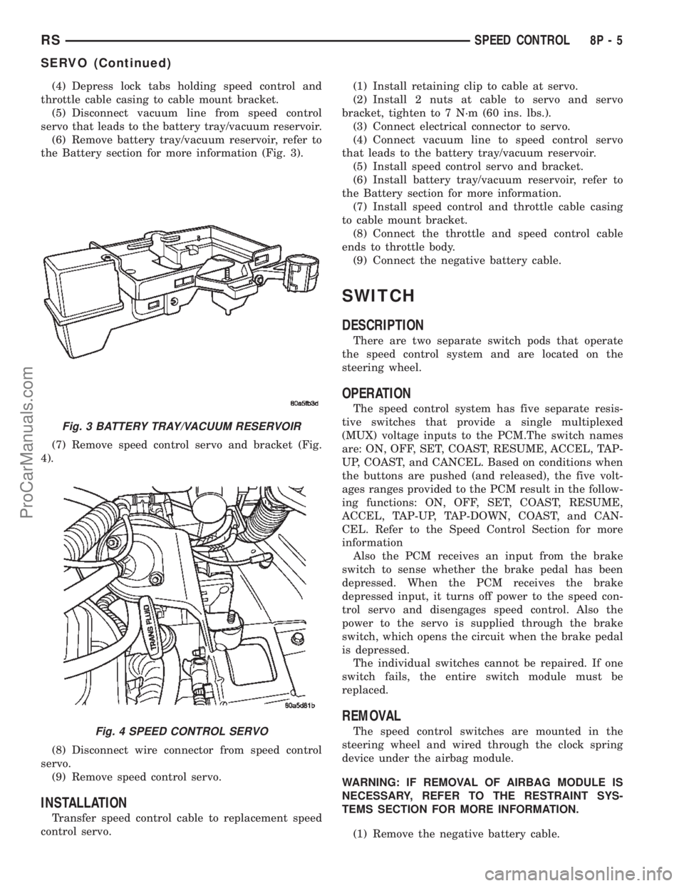
(6) Remove battery tray/vacuum reservoir, refer to
the Battery section for more information (Fig. 3).
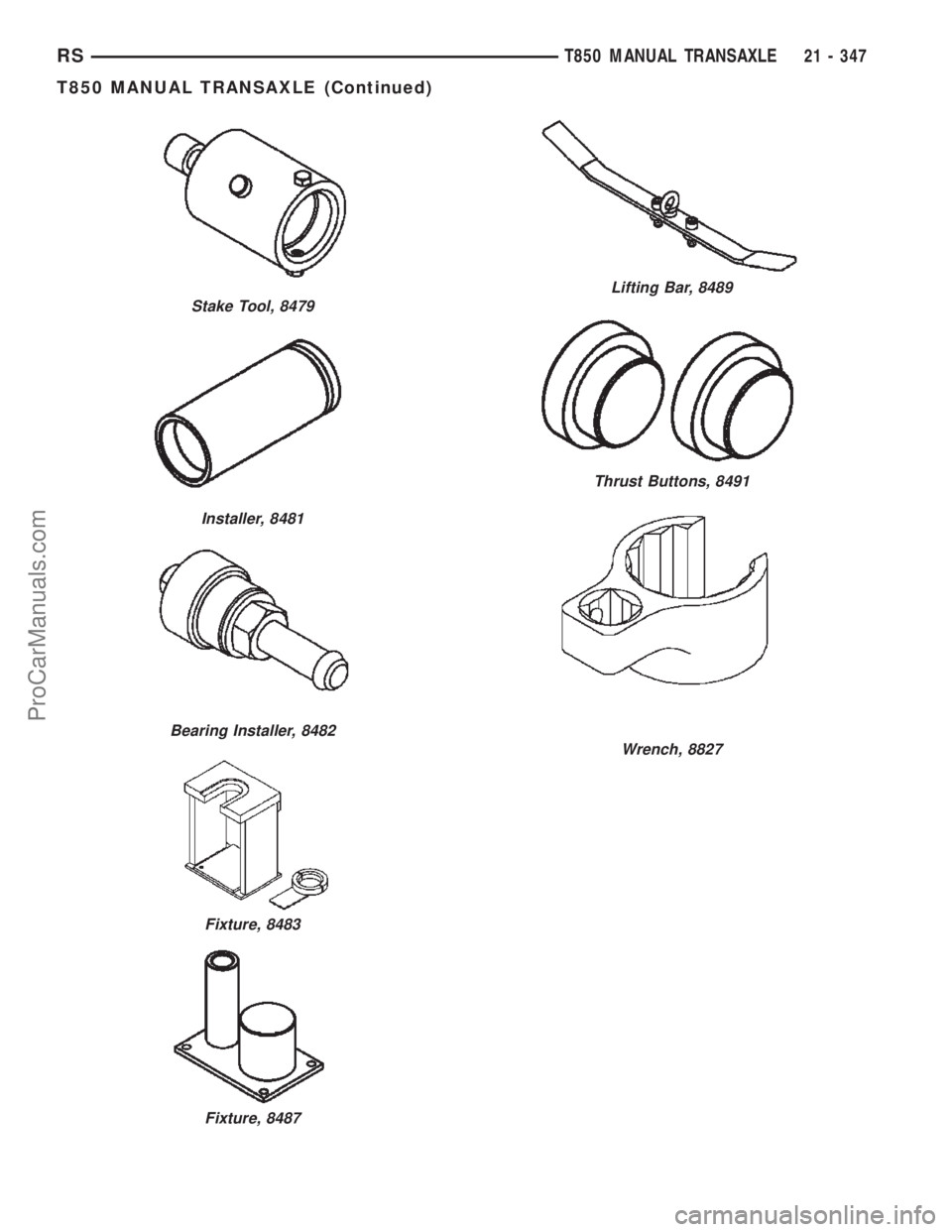
(7) Remove speed control servo and bracket (Fig.
4).
(8) Disconnect wire connector from speed control
servo.
(9) Remove speed control servo.
INSTALLATION
Transfer speed control cable to replacement speed
control servo.(1) Install retaining clip to cable at servo.
(2) Install 2 nuts at cable to servo and servo
bracket, tighten to 7 N´m (60 ins. lbs.).
(3) Connect electrical connector to servo.
(4) Connect vacuum line to speed control servo
that leads to the battery tray/vacuum reservoir.
(5) Install speed control servo and bracket.
(6) Install battery tray/vacuum reservoir, refer to
the Battery section for more information.
(7) Install speed control and throttle cable casing
to cable mount bracket.
(8) Connect the throttle and speed control cable
ends to throttle body.
(9) Connect the negative battery cable.
SWITCH
DESCRIPTION
There are two separate switch pods that operate
the speed control system and are located on the
steering wheel.
OPERATION
The speed control system has five separate resis-
tive switches that provide a single multiplexed
(MUX) voltage inputs to the PCM.The switch names
are: ON, OFF, SET, COAST, RESUME, ACCEL, TAP-
UP, COAST, and CANCEL. Based on conditions when
the buttons are pushed (and released), the five volt-
ages ranges provided to the PCM result in the follow-
ing functions: ON, OFF, SET, COAST, RESUME,
ACCEL, TAP-UP, TAP-DOWN, COAST, and CAN-
CEL. Refer to the Speed Control Section for more
information
Also the PCM receives an input from the brake
switch to sense whether the brake pedal has been
depressed. When the PCM receives the brake
depressed input, it turns off power to the speed con-
trol servo and disengages speed control. Also the
power to the servo is supplied through the brake
switch, which opens the circuit when the brake pedal
is depressed.
The individual switches cannot be repaired. If one
switch fails, the entire switch module must be
replaced.
REMOVAL
The speed control switches are mounted in the
steering wheel and wired through the clock spring
device under the airbag module.
WARNING: IF REMOVAL OF AIRBAG MODULE IS
NECESSARY, REFER TO THE RESTRAINT SYS-
TEMS SECTION FOR MORE INFORMATION.
(1) Remove the negative battery cable.
Fig. 3 BATTERY TRAY/VACUUM RESERVOIR
Fig. 4 SPEED CONTROL SERVO
RSSPEED CONTROL8P-5
SERVO (Continued)
ProCarManuals.com
Page 1904 of 2399

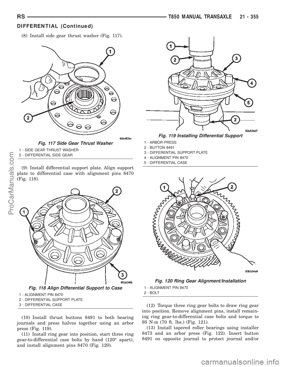
Stake Tool, 8479
Installer, 8481
Bearing Installer, 8482
Fixture, 8483
Fixture, 8487
Lifting Bar, 8489
Thrust Buttons, 8491
Wrench, 8827
RST850 MANUAL TRANSAXLE21 - 347
T850 MANUAL TRANSAXLE (Continued)
ProCarManuals.com
Page 1912 of 2399

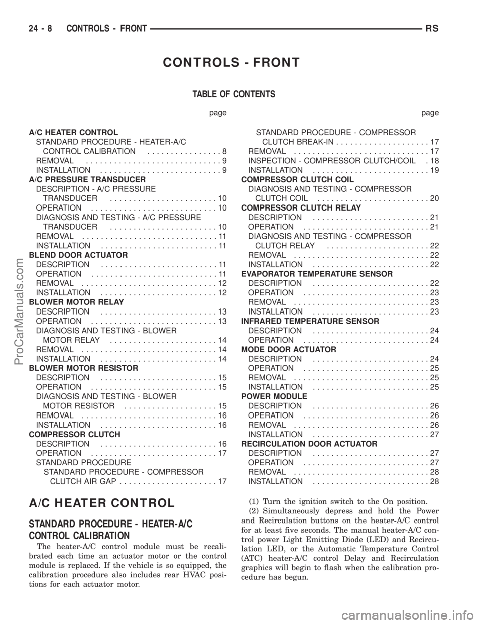
(8) Install side gear thrust washer (Fig. 117).
(9) Install differential support plate. Align support
plate to differential case with alignment pins 8470
(Fig. 118).
(10) Install thrust buttons 8491 to both bearing
journals and press halves together using an arbor
press (Fig. 119).
(11) Install ring gear into position, start three ring
gear-to-differential case bolts by hand (120É apart),
and install alignment pins 8470 (Fig. 120).(12) Torque three ring gear bolts to draw ring gear
into position. Remove alignment pins, install remain-
ing ring gear-to-differential case bolts and torque to
95 N´m (70 ft. lbs.) (Fig. 121).
(13) Install tapered roller bearings using installer
8473 and an arbor press (Fig. 122). Insert button
8491 on opposite journal to protect journal and/or
Fig. 117 Side Gear Thrust Washer
1 - SIDE GEAR THRUST WASHER
2 - DIFFERENTIAL SIDE GEAR
Fig. 118 Align Differential Support to Case
1 - ALIGNMENT PIN 8470
2 - DIFFERENTIAL SUPPORT PLATE
3 - DIFFERENTIAL CASE
Fig. 119 Installing Differential Support
1 - ARBOR PRESS
2 - BUTTON 8491
3 - DIFFERENTIAL SUPPORT PLATE
4 - ALIGNMENT PIN 8470
5 - DIFFERENTIAL CASE
Fig. 120 Ring Gear Alignment/Installation
1 - ALIGNMENT PIN 8470
2 - BOLT
RST850 MANUAL TRANSAXLE21 - 355
DIFFERENTIAL (Continued)
ProCarManuals.com
Page 2248 of 2399

control rear set temp button is pressed simulta-
neously with the rear control head, then the front
control head press events shall have priority, i.e. if
the front user presses Rear Set Temp down and the
rear user presses Set Temp up, then the rear set
temp will decrease.
DIAGNOSIS AND TESTING
DIAGNOSIS AND TESTING - A/C COOL DOWN
TEST
The heater-A/C control module can perform an A/C
cool down test, which is a test performed during the
manufacturing process to confirm that the air condi-
tioning system is performing satisfactorily. This test
can also provide a quick confirmation of air condi-
tioning system performance to the service technician.
If the test is completed satisfactorily, no further ser-
vice is required. If the test is failed, proceed to the
A/C Performance Test to confirm the a/c system is
operating properly, or use a DRBIIItscan tool to
diagnose the A/C system control and distribution sys-
tems. Refer to the appropriate diagnostic informa-
tion.
MANUAL TEMPERATURE CONTROL
The front blower speed and rear blower speed (if
equipped with rear HVAC) must be set to High and
the evaporator temperature sensor must be greater
than 55É F or the test will fail immediately. The test
is activated by depressing the A/C and PWR buttons
simultaneously and holding them depressed for no
less than five seconds. The PWR and A/C LEDs will
blink on and off until the test is complete. If the
LEDs stop blinking before two minutes, then the cool
down test has been completed successfully. If the two
minutes expire without the expansion valve temper-
ature reaching 20É F less than the outside air tem-
perature, then the cool down test has been failed and
further A/C system diagnosis is required. If the test
is failed, the LEDs will continue to blink until the
vehicle has been driven for greater than (8 miles).
AUTOMATIC TEMPERATURE CONTROL
The ambient air temperature in the room where
the vehicle will be tested must be a minimum of 21É
C (70ÉF) for this test. The test is activated by
depressing the A/C and PWR buttons simultaneously
and holding them depressed for no less than four sec-
onds. The snowflake icon and the DELAY text in the
ATC display will blink on and off alternately until
the test is complete. If the snowflake icon and the
DELAY text stop blinking before two minutes, then
the cool down test has been completed successfully. If
the two minutes expire without the evaporator tem-perature reaching 20É F less than the evaporator ini-
tial temperature, then the cool down test has been
failed and further A/C system diagnosis is required.
If the test is failed, the snowflake icon and the
DELAY text will continue to blink across ignition
cycles until the vehicle has been driven for greater
than (8 miles).
DIAGNOSIS AND TESTING - A/C
PERFORMANCE TEST
An air conditioning performance test is the best
way to determine whether the system is performing
up to standard. This test also provides valuable clues
as to the possible cause of trouble with the air con-
ditioning system. The ambient air temperature in the
location where the vehicle will be tested must be a
minimum of 21É C (70ÉF) for this test.
WARNING: REFER TO THE APPLICABLE WARN-
INGS AND CAUTIONS FOR THIS SYSTEM BEFORE
PERFORMING THE FOLLOWING OPERATION.
(Refer to 24 - HEATING & AIR CONDITIONING/
PLUMBING - FRONT - WARNING - A/C PLUMBING)
and (Refer to 24 - HEATING & AIR CONDITIONING/
PLUMBING - FRONT - CAUTION - A/C PLUMBING).
NOTE: When connecting the service equipment
coupling to the line fitting, verify that the valve of
the coupling is fully closed. This will reduce the
amount of effort required to make the connection.
(1) Connect a tachometer to monitor the engine
speed.
(2) Remove the caps from the refrigerant system
service ports and attach a manifold gauge set to
monitor the refrigerant system pressures.
(3) Set the heater-air conditioner controls so that
the compressor is engaged, the air within the vehicle
is being recirculated, the output air is directed
through the panel outlets, the temperature control is
in the full cool position, and the blower motor is oper-
ating at its highest speed.
(4) Start the engine and allow the engine to oper-
ate for about five minutes or until it reaches normal
operating temperature. Then hold the engine speed
at 1000 rpm with the compressor clutch engaged. If
the compressor clutch does not engage, proceed with
diagnosis of the compressor clutch coil. (Refer to 24 -
HEATING & AIR CONDITIONING/CONTROLS -
FRONT/COMPRESSOR CLUTCH COIL - DIAGNO-
SIS AND TESTING).
(5) Close all the vehicle windows and doors.
(6) Insert a thermometer in the left center panel
outlet and operate the engine for five minutes.
RSHEATING & AIR CONDITIONING24-5
HEATING & AIR CONDITIONING (Continued)
ProCarManuals.com
Page 2251 of 2399

CONTROLS - FRONT
TABLE OF CONTENTS
page page
A/C HEATER CONTROL
STANDARD PROCEDURE - HEATER-A/C
CONTROL CALIBRATION................8
REMOVAL.............................9
INSTALLATION..........................9
A/C PRESSURE TRANSDUCER
DESCRIPTION - A/C PRESSURE
TRANSDUCER.......................10
OPERATION...........................10
DIAGNOSIS AND TESTING - A/C PRESSURE
TRANSDUCER.......................10
REMOVAL.............................11
INSTALLATION.........................11
BLEND DOOR ACTUATOR
DESCRIPTION.........................11
OPERATION...........................11
REMOVAL.............................12
INSTALLATION.........................12
BLOWER MOTOR RELAY
DESCRIPTION.........................13
OPERATION...........................13
DIAGNOSIS AND TESTING - BLOWER
MOTOR RELAY.......................14
REMOVAL.............................14
INSTALLATION.........................14
BLOWER MOTOR RESISTOR
DESCRIPTION.........................15
OPERATION...........................15
DIAGNOSIS AND TESTING - BLOWER
MOTOR RESISTOR....................15
REMOVAL.............................16
INSTALLATION.........................16
COMPRESSOR CLUTCH
DESCRIPTION.........................16
OPERATION...........................17
STANDARD PROCEDURE
STANDARD PROCEDURE - COMPRESSOR
CLUTCH AIR GAP.....................17STANDARD PROCEDURE - COMPRESSOR
CLUTCH BREAK-IN....................17
REMOVAL.............................17
INSPECTION - COMPRESSOR CLUTCH/COIL . 18
INSTALLATION.........................19
COMPRESSOR CLUTCH COIL
DIAGNOSIS AND TESTING - COMPRESSOR
CLUTCH COIL........................20
COMPRESSOR CLUTCH RELAY
DESCRIPTION.........................21
OPERATION...........................21
DIAGNOSIS AND TESTING - COMPRESSOR
CLUTCH RELAY......................22
REMOVAL.............................22
INSTALLATION.........................22
EVAPORATOR TEMPERATURE SENSOR
DESCRIPTION.........................22
OPERATION...........................23
REMOVAL.............................23
INSTALLATION.........................23
INFRARED TEMPERATURE SENSOR
DESCRIPTION.........................24
OPERATION...........................24
MODE DOOR ACTUATOR
DESCRIPTION.........................24
OPERATION...........................25
REMOVAL.............................25
INSTALLATION.........................25
POWER MODULE
DESCRIPTION.........................26
OPERATION...........................26
REMOVAL.............................26
INSTALLATION.........................27
RECIRCULATION DOOR ACTUATOR
DESCRIPTION.........................27
OPERATION...........................27
REMOVAL.............................28
INSTALLATION.........................28
A/C HEATER CONTROL
STANDARD PROCEDURE - HEATER-A/C
CONTROL CALIBRATION
The heater-A/C control module must be recali-
brated each time an actuator motor or the control
module is replaced. If the vehicle is so equipped, the
calibration procedure also includes rear HVAC posi-
tions for each actuator motor.(1) Turn the ignition switch to the On position.
(2) Simultaneously depress and hold the Power
and Recirculation buttons on the heater-A/C control
for at least five seconds. The manual heater-A/C con-
trol power Light Emitting Diode (LED) and Recircu-
lation LED, or the Automatic Temperature Control
(ATC) heater-A/C control Delay and Recirculation
graphics will begin to flash when the calibration pro-
cedure has begun.
24 - 8 CONTROLS - FRONTRS
ProCarManuals.com