tire type CHRYSLER CARAVAN 2002 Owner's Manual
[x] Cancel search | Manufacturer: CHRYSLER, Model Year: 2002, Model line: CARAVAN, Model: CHRYSLER CARAVAN 2002Pages: 2399, PDF Size: 57.96 MB
Page 602 of 2399
cle. Check for battery voltage at the fused B(+)
circuit cavity of the power seat wire harness connec-
tor for the power seat switch. If OK, go to Step 4. If
not OK, repair the open fused B(+) circuit to the
power seat circuit breaker under the seat as
required.
(4) Check for continuity between the ground cir-
cuit cavity of the power seat wire harness connector
for the power seat switch and a good ground. There
should be continuity. If OK, go to Step 5. If not OK,
repair the open ground circuit to ground as required.
(5) Test the power seat switch. Refer toDiagnosis
and Testing Power Seat Switchin this section. If
the switch tests OK, test the circuits of the power
seat wire harness between the inoperative power seat
track adjuster motor and the power seat switch for
shorts or opens. If the circuits check OK, replace the
faulty power seat track unit. If the circuits are not
OK, repair the power seat wire harness as required.
REMOVAL
WARNING: SOME VEHICLES ARE EQUIPPED WITH
SEATBACK MOUNTED AIRBAGS. BEFORE
ATTEMPTING TO DIAGNOSE OR SERVICE ANY
SEAT OR POWER SEAT SYSTEM COMPONENT
YOU MUST FIRST DISCONNECT AND ISOLATE THE
BATTERY NEGATIVE CABLE. THEN WAIT TWO MIN-
UTES FOR THE SYSTEM CAPACITOR TO DIS-
CHARGE BEFORE FURTHER SYSTEM SERVICE.
THIS IS THE ONLY SURE WAY TO DISABLE THE
AIRBAG SYSTEM. FAILURE TO DO SO COULD
RESULT IN ACCIDENTAL AIRBAG DEPLOYMENT
AND POSSIBLE PERSONAL INJURY.
(1) Remove the appropriate seat from the vehicle
and place it on a clean work surface(Refer to 23 -
BODY/SEATS/SEAT - REMOVAL).
(2) Remove the Body Control Module retaining
screws.
(3) Disconnect the body control module electrical
connectors and remove the body control module from
the power seat track.
(4) Remove the rear fabric blocker trim panel from
the rear of the front seat.
(5) Remove the seat side cover and power seat
switch as an assembly (Refer to 23 - BODY/SEATS/
SEAT CUSHION SIDE COVERS - REMOVAL).
(6) Disconnect all electrical connectors connecting
the power seat track to the seat assembly.
(7) Pull the seat back trim cover up slightly to
access and remove the two seat back frame mounting
bolts and also remove two seat back recliner bolts.
(8) Remove four seat track mounting bolts from
the seat cushion pan.
(9) Remove the power seat track from the seat.
INSTALLATION
(1) Position the seat cushion on the seat track.
(2) Install the four seat track retaining bolts in the
seat cushion pan. Torque the bolts to 28.5 N´m.
(3) Position the seat back and install the two seat
back frame mounting bolts and the two seat back
recliner bolts. Torque the bolts to 55 N´m.
(4) Route and connect the electrical connectors
between the power seat track and the seat assembly.
(5) Install the seat side cover and power seat
switch as an assembly (Refer to 23 - BODY/SEATS/
SEAT CUSHION SIDE COVERS - INSTALLATION).
(6) Install the rear fabric blocker trim panel on the
rear of the front seat.
(7) Position the body control module and connect
the body control module electrical connectors.
(8) Install the Body Control Module retaining
screws.
(9) Install the seat assembly in the vehicle (Refer
to 23 - BODY/SEATS/SEAT - INSTALLATION).
PASSENGER POWER SEAT
TRACK
DESCRIPTION
The eight-way power seat option includes a electri-
cally operated power seat track unit located under
each front seat. The power seat circuit breaker is
mounted on the rear of the power seat track, just
behind the seat rear trim panel. The lower half of the
power seat track is secured to the floor panel via four
studs and nuts that must be accessed from the
underside of the vehicle. Four bolts secure the bot-
tom of the seat cushion frame to the upper half of the
power seat track unit. Four additional bolts secure
the seat back frame to the power seat track unit.
The power seat track unit includes four reversible
electric motors that are secured to the upper half of
the track unit. Each motor moves the seat adjuster
through a combination of worm-drive gearboxes and
screw-type drive units.
The front and rear of the seat are operated by two
separate vertical adjustment motors. These motors
can be operated independently of each other, tilting
the entire seat assembly forward or rearward; or,
they can be operated in unison by selecting the
proper power seat switch functions, which will raise
or lower the entire seat assembly. A third motor is
the horizontal adjustment motor, which moves the
seat track in the forward and rearward directions.
The forth motor is the recliner adjustment motor,
which moves the seat back in the forward and rear-
ward directions.
RSPOWER SEAT SYSTEM8N-61
DRIVER POWER SEAT TRACK (Continued)
ProCarManuals.com
Page 674 of 2399
WIRE
STANDARD PROCEDURE - WIRE SPLICING
When splicing a wire, it is important that the cor-
rect gage be used as shown in the wiring diagrams.
(1) Remove one-half (1/2) inch of insulation from
each wire that needs to be spliced.
(2) Place a piece of adhesive lined heat shrink tub-
ing on one side of the wire. Make sure the tubing will
be long enough to cover and seal the entire repair
area.
(3) Place the strands of wire overlapping each
other inside of the splice clip (Fig. 14).
(4) Using crimping tool, Mopar p/n 05019912AA,
crimp the splice clip and wires together (Fig. 15).(5) Solder the connection together using rosin core
type solder only (Fig. 16).
CAUTION: DO NOT USE ACID CORE SOLDER.
(6) Center the heat shrink tubing over the joint
and heat using a heat gun. Heat the joint until the
tubing is tightly sealed and sealant comes out of both
ends of the tubing (Fig. 17).
Fig. 14 SPLICE BAND
1 - SPLICE BAND
Fig. 15 CRIMPING TOOL
1 - CRIMPING TOOL
Fig. 16 SOLDER SPLICE
1 - SOLDER
2 - SPLICE BAND
3 - SOLDERING IRON
Fig. 17 HEAT SHRINK TUBE
1 - SEALANT
2 - HEAT SHRINK TUBE
RS8W-01 WIRING DIAGRAM INFORMATION8W-01-15
ProCarManuals.com
Page 1214 of 2399
NOTE: When the transaxle cooler lines are removed
from the rolled-groove type fittings at the transaxle,
damage to the inner wall of the hose will occur. To
prevent prevent potential leakage, the cooler hoses
must be cut off flush at the transaxle fitting, and a
service cooler hose splice kit must be installed
upon reassembly.
(9) Using a blade or suitable hose cutter, cut trans-
axle oil cooler lines off flush with fittings. Plug cooler
lines and fittings to prevent debris from entering
transaxle or cooler circuit. A service splice kit will be
installed upon reassembly.
(10) Disconnect transmission shift linkage and
electrical connectors.
(11) Disconnect throttle body linkage.
(12) Disconnect engine wiring harness.
(13) Disconnect heater hoses from heater (Fig. 5).(14) Discharge air conditioning system. (Refer to
24 - HEATING & AIR CONDITIONING/PLUMBING
- STANDARD PROCEDURE)
(15) Hoist vehicle and remove front wheels and
tires.
(16) Remove accessory drive belt splash shield.
(17) Remove accessory drive belts. (Refer to 7 -
COOLING/ACCESSORY DRIVE/DRIVE BELTS -
REMOVAL)
(18) Remove axle shafts. (Refer to 3 - DIFFEREN-
TIAL & DRIVELINE/HALF SHAFT - REMOVAL)
(19) Drain engine oil and remove oil filter. (Refer
to 9 - ENGINE/LUBRICATION/OIL - STANDARD
PROCEDURE)
(20) Remove crossmember cradle plate (Fig. 6).
(21) Disconnect exhaust pipe from manifold (Fig.
7).
Fig. 5 HEATER HOSES - 2.4L
1 - HEATER HOSES TO HEATER 3 - HEATER HOSE TO ENGINE - SUPPLY AND RETURN
2 - BOLT - HEATER TUBE SUPPORT
RSENGINE 2.4L9-13
ENGINE 2.4L (Continued)
ProCarManuals.com
Page 1285 of 2399
Calibrate the tester according to the manufactur-
er's instructions. The shop air source for testing
should maintain 483 kPa (70 psi) minimum, 1,379
kPa (200 psi) maximum, with 552 kPa (80 psi) rec-
ommended.
Perform the test procedures on each cylinder
according to the tester manufacturer's instructions.
While testing, listen for pressurized air escaping
through the throttle body, tailpipe and oil filler cap
opening. Check for bubbles in the coolant.
All gauge pressure indications should be equal,
with no more than 25% leakage per cylinder.
FOR EXAMPLE:At 552 kPa (80 psi) input pres-
sure, a minimum of 414 kPa (60 psi) should be main-
tained in the cylinder.
STANDARD PROCEDURE
STANDARD PROCEDURE - MEASURING
BEARING CLEARANCE USING PLASTIGAGE
Engine crankshaft bearing clearances can be deter-
mined by use of Plastigage or equivalent. The follow-
ing is the recommended procedure for the use of
Plastigage:
(1) Remove oil film from surface to be checked.
Plastigage is soluble in oil.
(2) Place a piece of Plastigage across the entire
width of the bearing shell in the cap approximately
6.35 mm (1/4 in.) off center and away from the oil
holes (Fig. 3). (In addition, suspected areas can be
checked by placing the Plastigage in the suspected
area). Torque the bearing cap bolts of the bearing
being checked to the proper specifications.(3) Remove the bearing cap and compare the
width of the flattened Plastigage with the metric
scale provided on the package. Locate the band clos-
est to the same width. This band shows the amount
of clearance in thousandths of a millimeter. Differ-
ences in readings between the ends indicate the
amount of taper present. Record all readings taken.
Compare clearance measurements to specs found in
engine specifications (Refer to 9 - ENGINE - SPECI-
FICATIONS).Plastigage generally is accompa-
nied by two scales. One scale is in inches, the
other is a metric scale.
NOTE: Plastigage is available in a variety of clear-
ance ranges. Use the most appropriate range for
the specifications you are checking.
(4) Install the proper crankshaft bearings to
achieve the specified bearing clearances.
STANDARD PROCEDURE - FORM-IN-PLACE
GASKETS AND SEALERS
There are numerous places where form-in-place
gaskets are used on the engine. Care must be taken
when applying form-in-place gaskets to assure
obtaining the desired results.Do not use form-in-
place gasket material unless specified.Bead size,
continuity, and location are of great importance. Too
thin a bead can result in leakage while too much can
result in spill-over which can break off and obstruct
fluid feed lines. A continuous bead of the proper
width is essential to obtain a leak-free gasket.
There are numerous types of form-in-place gasket
materials that are used in the engine area. Mopart
Engine RTV GEN II, MopartATF-RTV, and Mopart
Gasket Maker gasket materials, each have different
properties and can not be used in place of the other.
MOPARtENGINE RTV GEN IIis used to seal
components exposed to engine oil. This material is a
specially designed black silicone rubber RTV that
retains adhesion and sealing properties when
exposed to engine oil. Moisture in the air causes the
material to cure. This material is available in three
ounce tubes and has a shelf life of one year. After one
year this material will not properly cure. Always
inspect the package for the expiration date before
use.
MOPARtATF RTVis a specifically designed
black silicone rubber RTV that retains adhesion and
sealing properties to seal components exposed to
automatic transmission fluid, engine coolants, and
moisture. This material is available in three ounce
tubes and has a shelf life of one year. After one year
this material will not properly cure. Always inspect
the package for the expiration date before use.
Fig. 3 Plastigage Placed in Lower ShellÐTypical
1 - PLASTIGAGE
9 - 84 ENGINE 3.3/3.8LRS
ENGINE 3.3/3.8L (Continued)
ProCarManuals.com
Page 1509 of 2399
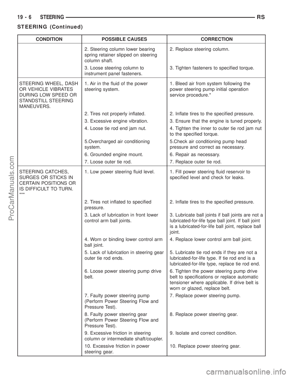
CONDITION POSSIBLE CAUSES CORRECTION
2. Steering column lower bearing
spring retainer slipped on steering
column shaft.2. Replace steering column.
3. Loose steering column to
instrument panel fasteners.3. Tighten fasteners to specified torque.
STEERING WHEEL, DASH
OR VEHICLE VIBRATES
DURING LOW SPEED OR
STANDSTILL STEERING
MANEUVERS.1. Air in the fluid of the power
steering system.1. Bleed air from system following the
power steering pump initial operation
service procedure.*
2. Tires not properly inflated. 2. Inflate tires to the specified pressure.
3. Excessive engine vibration. 3. Ensure that the engine is tuned properly.
4. Loose tie rod end jam nut. 4. Tighten the inner to outer tie rod jam nut
to the specified torque.
5.Overcharged air conditioning
system.5.Check air conditioning pump head
pressure and correct as necessary.
6. Grounded engine mount. 6. Repair as necessary.
7. Loose outer tie rod. 7. Replace outer tie rod.
STEERING CATCHES,
SURGES OR STICKS IN
CERTAIN POSITIONS OR
IS DIFFICULT TO TURN.
***1. Low power steering fluid level. 1. Fill power steering fluid reservoir to
specified level and check for leaks.
2. Tires not inflated to specified
pressure.2. Inflate tires to the specified pressure.
3. Lack of lubrication in front lower
control arm ball joints.3. Lubricate ball joints if ball joints are not a
lubricated-for-life type ball joint. If ball joint
is a lubricated-for-life ball joint, replace ball
joint.
4. Worn or binding lower control arm
ball joint.4. Replace lower control arm ball joint.
5. Lack of lubrication in steering gear
outer tie rod ends.5. Lubricate tie rod ends if they are not a
lubricated-for-life type. If tie rod end is a
lubricated-for-life type, replace tie rod end.
6. Loose power steering pump drive
belt.6. Tighten the power steering pump drive
belt to specifications or replace automatic
tensioner where applicable. If drive belt is
worn or glazed, replace belt.
7. Faulty power steering pump
(Perform Power Steering Flow and
Pressure Test).7. Replace power steering pump.
8. Faulty power steering gear
(Perform Power Steering Flow and
Pressure Test).8. Replace power steering gear.
9. Excessive friction in steering
column or intermediate shaft/coupler.9. Isolate and correct condition.
10. Excessive friction in power
steering gear.10. Replace power steering gear.
19 - 6 STEERINGRS
STEERING (Continued)
ProCarManuals.com
Page 1510 of 2399
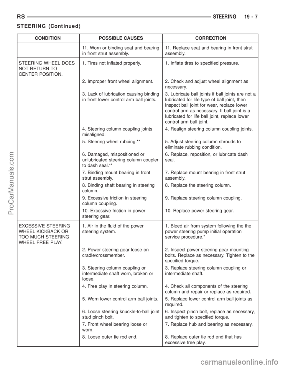
CONDITION POSSIBLE CAUSES CORRECTION
11. Worn or binding seat and bearing
in front strut assembly.11. Replace seat and bearing in front strut
assembly.
STEERING WHEEL DOES
NOT RETURN TO
CENTER POSITION.1. Tires not inflated properly. 1. Inflate tires to specified pressure.
2. Improper front wheel alignment. 2. Check and adjust wheel alignment as
necessary.
3. Lack of lubrication causing binding
in front lower control arm ball joints.3. Lubricate ball joints if ball joints are not a
lubricated for life type of ball joint, then
inspect ball joint for wear, replace lower
control arm as necessary. If ball joint is a
lubricated for life ball joint, replace lower
control arm ball joint.
4. Steering column coupling joints
misaligned.4. Realign steering column coupling joints.
5. Steering wheel rubbing.** 5. Adjust steering column shrouds to
eliminate rubbing condition.
6. Damaged, mispositioned or
unlubricated steering column coupler
to dash seal.**6. Replace, reposition, or lubricate dash
seal.
7. Binding mount bearing in front
strut assembly.7. Replace mount bearing in front strut
assembly.
8. Binding shaft bearing in steering
column.8. Replace the steering column.
9. Excessive friction in steering
column coupling.9. Replace steering column coupling.
10. Excessive friction in power
steering gear.10. Replace power steering gear.
EXCESSIVE STEERING
WHEEL KICKBACK OR
TOO MUCH STEERING
WHEEL FREE PLAY.1. Air in the fluid of the power
steering system.1. Bleed air from system following the the
power steering pump initial operation
service procedure.*
2. Power steering gear loose on
cradle/crossmember.2. Inspect power steering gear mounting
bolts. Replace as necessary. Tighten to the
specified torque.
3. Steering column coupling or
intermediate shaft worn, broken or
loose.3. Replace steering column coupling or
intermediate shaft.
4. Free play in steering column. 4. Check all components of the steering
column and repair or replace as required.
5. Worn lower control arm ball joints. 5. Replace lower control arm ball joints as
required.
6. Loose steering knuckle-to-ball joint
stud pinch bolt.6. Inspect pinch bolt, replace as necessary,
and tighten to specified torque.
7. Front wheel bearing loose or
worn.7. Replace hub and bearing as necessary.
8. Loose outer tie rod end. 8. Replace outer tie rod end that has
excessive free play.
RSSTEERING19-7
STEERING (Continued)
ProCarManuals.com
Page 1548 of 2399

FLUID COOLER
DESCRIPTION
All models (except 2.5L Diesel) are equipped with a
cooler for the power steering system fluid. The power
steering fluid cooler is located on the front suspen-
sion cradle crossmember reinforcement (Fig. 18).
There are two different size coolers depending on
model and options. There is a standard 6-inch and an
8-inch.
OPERATION
The purpose of the power steering fluid cooler is to
keep the temperature of the power steering system
fluid from rising to a level that would affect the per-
formance of the power steering system.
The cooler used on this vehicle is referred to as a
fluid-to-air type cooler. This means that the air flow
across the tubes (and fines surrounding them) of the
cooler is used to extract the heat from the cooler
which it has absorbed from the power steering fluid
flowing through it. The cooler is placed in the power
steering fluid return line, between the steering gear
and the power steering fluid reservoir.
REMOVAL
(1) Using a siphon pump, remove as much fluid as
possible from the power steering fluid reservoir.
(2) Raise vehicle. (Refer to LUBRICATION &
MAINTENANCE/HOISTING - STANDARD PROCE-
DURE)
(3) Remove the hose clamps at the cooler and
remove the hoses from the cooler inlet and outlet
tubes.
(4) Remove the 2 bolts attaching the power steer-
ing cooler cradle crossmember reinforcement (Fig.
18). Remove the cooler.
INSTALLATION
(1) Install the power steering fluid cooler on the
cradle crossmember reinforcement (Fig. 18). Install
the mounting bolts and tighten to 11 N´m (100 in.
lbs.).
(2) Install power steering fluid hoses on the cooler.
Be sure hose clamps are installed on hose past
the upset bead on the power steering cooler
tubes.(3) Lower the vehicle to a point where front tires
are just off the ground.
(4) Perform Power Steering Pump Initial Opera-
tion procedure. (Refer to 19 - STEERING/PUMP -
STANDARD PROCEDURE)
HOSE - POWER STEERING
PRESSURE
REMOVAL
REMOVAL - 2.4L ENGINE
NOTE: Before proceeding, review all WARNINGS
and CAUTIONS. (Refer to 19 - STEERING/PUMP -
WARNING)(Refer to 19 - STEERING/PUMP - CAU-
TION)
(1) Remove cap from power steering fluid reser-
voir.
(2) Using a siphon pump, remove as much power
steering fluid as possible from power steering fluid
reservoir.
Fig. 18 Power Steering Cooler
1 - CRADLE CROSSMEMBER REINFORCEMENT
2 - POWER STEERING COOLER
RSPUMP19-45
ProCarManuals.com
Page 1553 of 2399

INSTALLATION
INSTALLATION - 2.4L ENGINE
(1) Remove any used O-rings from ends of power
steering hose.
(2) Using a lint free towel, wipe clean hose ends,
power steering pump fitting and steering gear port.
(3) Install new O-ring on power steering gear end
of return hose. Lubricate O-ring using clean power
steering fluid.
CAUTION: Use care not to bend tube ends of the
power steering hoses when installing. Leaks and
restrictions may occur.
CAUTION: If a new return hose is being installed
and it does not have an insulating heat sleeve
installed, the heat shield from the original hose
must be transferred before hose installation.
(4) Route hose along rear of cradle crossmember
and start gear end of hose into gear port. Do not
tighten hose tube nut at this time.
(5) Attach hose to suspension cradle crossmember
using two routing clamps and bolts (Fig. 19). Tighten
clamp bolts to 23 N´m (200 in. lbs.) torque.
(6) Tighten return hose tube nut at power steering
gear port to 31 N´m (275 in. lbs.) torque.
(7) Install the power steering fluid cooler on the
cradle crossmember reinforcement (Fig. 23). Install
the mounting bolts and tighten to 11 N´m (100 in.
lbs.).
CAUTION: Power steering fluid hoses must remain
away from the exhaust system and must not come
in contact with any unfriendly surfaces on the vehi-
cle.
(8) Route pump end of hose over cradle crossmem-
ber toward pump avoiding tight bends or kinking.
(9) Install return hose onto power steering pump
return fitting and secure with hose clamp (Fig. 19).
Tighten the screw-type clamp to a torque of 2 N´m
(18 in. lbs.).
CAUTION: To prevent overheating of power steering
fluid return hose, protective heat shield sleeve must
cover entire rubber hose.
(10) Slide insulating heat shield up over the clamp
on the return hose and tie-strap it in place.
(11) Install front emissions vapor canister. (Refer
to 25 - EMISSIONS CONTROL/EVAPORATIVE
EMISSIONS/VAPOR CANISTER - INSTALLATION)
(12) Lower vehicle.(13) Fill and bleed the power steering system
using the Power Steering Pump Initial Operation
Procedure. (Refer to 19 - STEERING/PUMP - STAN-
DARD PROCEDURE)
(14) Inspect system for leaks.
INSTALLATION - 3.3L/3.8L ENGINE
(1) Remove any used O-rings from ends of power
steering hose.
(2) Using a lint free towel, wipe clean hose ends
and power steering gear hose port.
(3) Install a new O-ring on gear port end of power
steering fluid hose. Lubricate O-ring using clean
power steering fluid.
CAUTION: Use care not to bend tube ends of the
power steering hoses when installing. Leaks and
restrictions may occur.
CAUTION: Power steering fluid hoses must remain
away from the exhaust system and must not come
in contact with any unfriendly surfaces on the vehi-
cle.
(4) Route hose (with cooler attached) up toward
reservoir avoiding tight bends or kinking.
(5) Start steering gear end of hose into gear port.
Do not tighten hose tube nut at this time.
(6) Attach return hose tubes to suspension cradle
crossmember using routing clamp and bolt (Fig. 20).
Tighten clamp bolt to 23 N´m (200 in. lbs.) torque.
(7) Install the power steering fluid cooler on the
cradle crossmember reinforcement (Fig. 23). Install
the mounting bolts and tighten to 11 N´m (100 in.
lbs.). When installing mounting bolts, include pres-
sure hose routing clamp.
(8) Tighten hose tube nut at power steering gear
port to 31 N´m (275 in. lbs.) torque.
(9) Install front emissions vapor canister. (Refer to
25 - EMISSIONS CONTROL/EVAPORATIVE EMIS-
SIONS/VAPOR CANISTER - INSTALLATION)
(10) Lower vehicle.
(11) Install return hose tube into retainer on ABS
bracket (Fig. 20). Close the bracket.
(12) Install return hose onto reservoir (Fig. 21).
Slide the hose clamp into position on fluid reservoir
and attach it.Be sure hose clamp in installed
past bead on fluid reservoir fitting.
(13) Fill and bleed power steering system using
the Power Steering Pump Initial Operation Proce-
dure. (Refer to 19 - STEERING/PUMP - STANDARD
PROCEDURE)
(14) Inspect system for leaks.
19 - 50 PUMPRS
HOSE - POWER STEERING RETURN (Continued)
ProCarManuals.com
Page 1965 of 2399
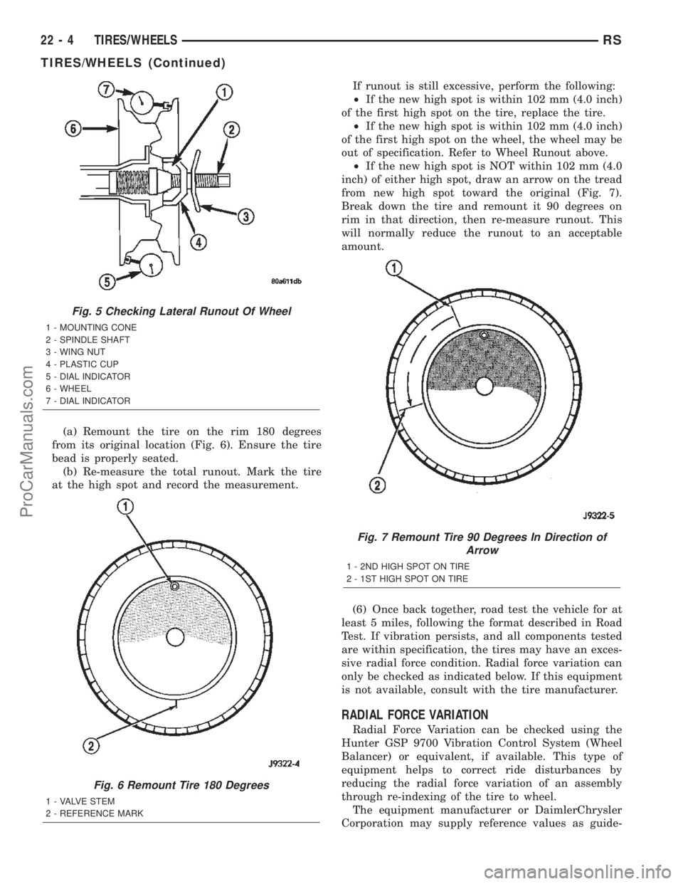
(a) Remount the tire on the rim 180 degrees
from its original location (Fig. 6). Ensure the tire
bead is properly seated.
(b) Re-measure the total runout. Mark the tire
at the high spot and record the measurement.If runout is still excessive, perform the following:
²If the new high spot is within 102 mm (4.0 inch)
of the first high spot on the tire, replace the tire.
²If the new high spot is within 102 mm (4.0 inch)
of the first high spot on the wheel, the wheel may be
out of specification. Refer to Wheel Runout above.
²If the new high spot is NOT within 102 mm (4.0
inch) of either high spot, draw an arrow on the tread
from new high spot toward the original (Fig. 7).
Break down the tire and remount it 90 degrees on
rim in that direction, then re-measure runout. This
will normally reduce the runout to an acceptable
amount.
(6) Once back together, road test the vehicle for at
least 5 miles, following the format described in Road
Test. If vibration persists, and all components tested
are within specification, the tires may have an exces-
sive radial force condition. Radial force variation can
only be checked as indicated below. If this equipment
is not available, consult with the tire manufacturer.
RADIAL FORCE VARIATION
Radial Force Variation can be checked using the
Hunter GSP 9700 Vibration Control System (Wheel
Balancer) or equivalent, if available. This type of
equipment helps to correct ride disturbances by
reducing the radial force variation of an assembly
through re-indexing of the tire to wheel.
The equipment manufacturer or DaimlerChrysler
Corporation may supply reference values as guide-
Fig. 5 Checking Lateral Runout Of Wheel
1 - MOUNTING CONE
2 - SPINDLE SHAFT
3 - WING NUT
4 - PLASTIC CUP
5 - DIAL INDICATOR
6 - WHEEL
7 - DIAL INDICATOR
Fig. 6 Remount Tire 180 Degrees
1 - VALVE STEM
2 - REFERENCE MARK
Fig. 7 Remount Tire 90 Degrees In Direction of
Arrow
1 - 2ND HIGH SPOT ON TIRE
2 - 1ST HIGH SPOT ON TIRE
22 - 4 TIRES/WHEELSRS
TIRES/WHEELS (Continued)
ProCarManuals.com
Page 1966 of 2399
lines. Radial force measurements above the reference
value may not always result in a ride disturbance,
nor do they automatically mean the assembly compo-
nents are out of specification. Do not replace compo-
nents based on radial force values alone. Balancing,
runout diagnosis, re-indexing, and subjective road
testing must be performed as outlined in previous
sections of this diagnosis and testing procedure.
Use the Radial Force equipment to identify suspect
assemblies and minimize the radial forces. After all
suspect assemblies are optimized, reinstall the
assemblies and road test the vehicle. If a disturbance
still exists and all other vibration diagnostic proce-
dures have been completed, replace one tire or one
wheel at a time, starting with the assembly having
the highest force variation. Be sure to minimize each
new assembly. Road test the vehicle following each
replacement. Continue this process until the distur-
bance is resolved.
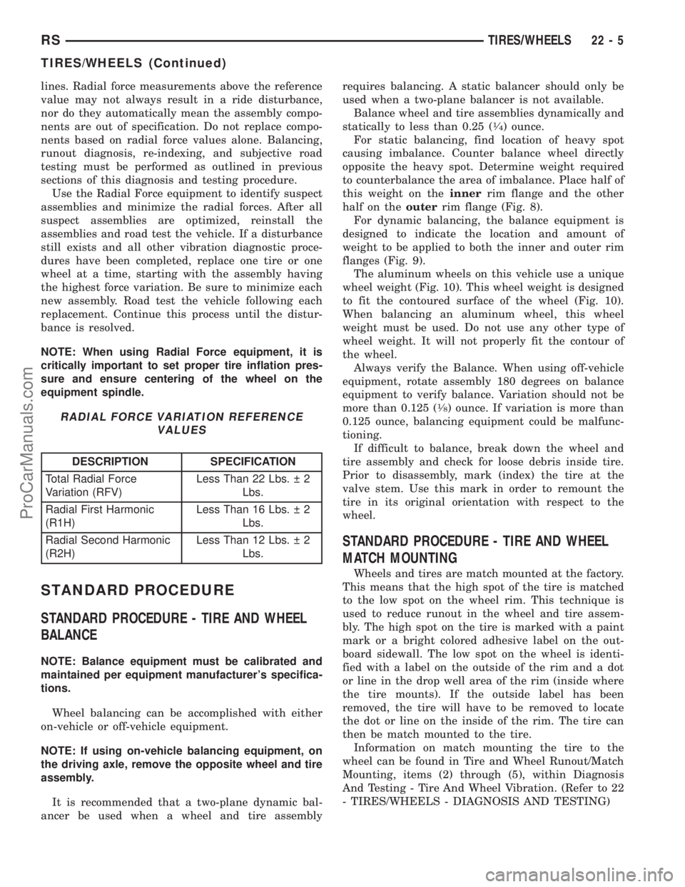
NOTE: When using Radial Force equipment, it is
critically important to set proper tire inflation pres-
sure and ensure centering of the wheel on the
equipment spindle.
RADIAL FORCE VARIATION REFERENCE
VALUES
DESCRIPTION SPECIFICATION
Total Radial Force
Variation (RFV)Less Than 22 Lbs. 2
Lbs.
Radial First Harmonic
(R1H)Less Than 16 Lbs. 2
Lbs.
Radial Second Harmonic
(R2H)Less Than 12 Lbs. 2
Lbs.
STANDARD PROCEDURE
STANDARD PROCEDURE - TIRE AND WHEEL
BALANCE
NOTE: Balance equipment must be calibrated and
maintained per equipment manufacturer's specifica-
tions.
Wheel balancing can be accomplished with either
on-vehicle or off-vehicle equipment.
NOTE: If using on-vehicle balancing equipment, on
the driving axle, remove the opposite wheel and tire
assembly.
It is recommended that a two-plane dynamic bal-
ancer be used when a wheel and tire assemblyrequires balancing. A static balancer should only be
used when a two-plane balancer is not available.
Balance wheel and tire assemblies dynamically and
statically to less than 0.25 (
1¤4) ounce.
For static balancing, find location of heavy spot
causing imbalance. Counter balance wheel directly
opposite the heavy spot. Determine weight required
to counterbalance the area of imbalance. Place half of
this weight on theinnerrim flange and the other
half on theouterrim flange (Fig. 8).
For dynamic balancing, the balance equipment is
designed to indicate the location and amount of
weight to be applied to both the inner and outer rim
flanges (Fig. 9).
The aluminum wheels on this vehicle use a unique
wheel weight (Fig. 10). This wheel weight is designed
to fit the contoured surface of the wheel (Fig. 10).
When balancing an aluminum wheel, this wheel
weight must be used. Do not use any other type of
wheel weight. It will not properly fit the contour of
the wheel.
Always verify the Balance. When using off-vehicle
equipment, rotate assembly 180 degrees on balance
equipment to verify balance. Variation should not be
more than 0.125 (
1¤8) ounce. If variation is more than
0.125 ounce, balancing equipment could be malfunc-
tioning.
If difficult to balance, break down the wheel and
tire assembly and check for loose debris inside tire.
Prior to disassembly, mark (index) the tire at the
valve stem. Use this mark in order to remount the
tire in its original orientation with respect to the
wheel.
STANDARD PROCEDURE - TIRE AND WHEEL
MATCH MOUNTING
Wheels and tires are match mounted at the factory.
This means that the high spot of the tire is matched
to the low spot on the wheel rim. This technique is
used to reduce runout in the wheel and tire assem-
bly. The high spot on the tire is marked with a paint
mark or a bright colored adhesive label on the out-
board sidewall. The low spot on the wheel is identi-
fied with a label on the outside of the rim and a dot
or line in the drop well area of the rim (inside where
the tire mounts). If the outside label has been
removed, the tire will have to be removed to locate
the dot or line on the inside of the rim. The tire can
then be match mounted to the tire.
Information on match mounting the tire to the
wheel can be found in Tire and Wheel Runout/Match
Mounting, items (2) through (5), within Diagnosis
And Testing - Tire And Wheel Vibration. (Refer to 22
- TIRES/WHEELS - DIAGNOSIS AND TESTING)
RSTIRES/WHEELS22-5
TIRES/WHEELS (Continued)
ProCarManuals.com