wheel alignment CHRYSLER CARAVAN 2002 Owner's Manual
[x] Cancel search | Manufacturer: CHRYSLER, Model Year: 2002, Model line: CARAVAN, Model: CHRYSLER CARAVAN 2002Pages: 2399, PDF Size: 57.96 MB
Page 240 of 2399
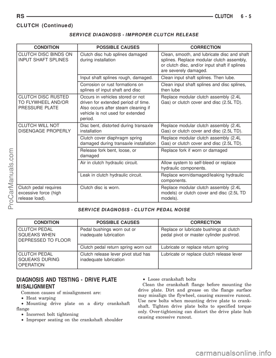
SERVICE DIAGNOSIS - IMPROPER CLUTCH RELEASE
CONDITION POSSIBLE CAUSES CORRECTION
CLUTCH DISC BINDS ON
INPUT SHAFT SPLINESClutch disc hub splines damaged
during installationClean, smooth, and lubricate disc and shaft
splines. Replace modular clutch assembly,
or clutch disc, and/or input shaft if splines
are severely damaged.
Input shaft splines rough, damaged. Clean input shaft splines. Then lube.
Corrosion or rust formations on
splines of input shaft and discClean input shaft splines and disc splines,
then lube
CLUTCH DISC RUSTED
TO FLYWHEEL AND/OR
PRESSURE PLATEOccurs in vehicles stored or not
driven for extended period of time.
Also occurs after steam cleaning if
vehicle is not used for extended
period.Replace modular clutch assembly (2.4L
Gas) or clutch cover and disc (2.5L TD).
CLUTCH WILL NOT
DISENGAGE PROPERLYDisc bent, distorted during transaxle
installationReplace modular clutch assembly (2.4L
Gas) or clutch cover and disc (2.5L TD).
Clutch cover diaphragm spring
damaged during transaxle installationReplace modular clutch assembly (2.4L
Gas) or clutch cover and disc (2.5L TD).
Release fork bent, loose, or
damagedReplace fork if worn or damaged
Air in clutch hydraulic circuit. Allow system to self-bleed or replace
hydraulic components.
Leak in clutch hydraulic circuit. Replace worn/damaged/leaking hydraulic
components.
Clutch pedal requires
excessive force (high
release load).Clutch disc is worn. Replace modular clutch assembly (2.4L
models) or clutch cover and disc (2.5L TD
models).
SERVICE DIAGNOSIS - CLUTCH PEDAL NOISE
CONDITION POSSIBLE CAUSES CORRECTION
CLUTCH PEDAL
SQUEAKS WHEN
DEPRESSED TO FLOORPedal bushings worn out or
inadequate lubricationReplace or lubricate bushings at clutch
pedal pivot or master cylinder pushrod.
Clutch pedal return spring worn out Lubricate or replace return spring
CLUTCH PEDAL
SQUEAKS DURING
OPERATIONClutch release lever pivot stud has
inadequate lubricationLubricate or replace clutch release lever
DIAGNOSIS AND TESTING - DRIVE PLATE
MISALIGNMENT
Common causes of misalignment are:
²Heat warping
²Mounting drive plate on a dirty crankshaft
flange
²Incorrect bolt tightening
²Improper seating on the crankshaft shoulder²Loose crankshaft bolts
Clean the crankshaft flange before mounting the
drive plate. Dirt and grease on the flange surface
may misalign the flywheel, causing excessive runout.
Use new bolts when mounting drive plate to crank-
shaft. Tighten drive plate bolts to specified torque
only. Over-tightening can distort the drive plate hub
causing excessive runout.
RSCLUTCH6-5
CLUTCH (Continued)
ProCarManuals.com
Page 247 of 2399
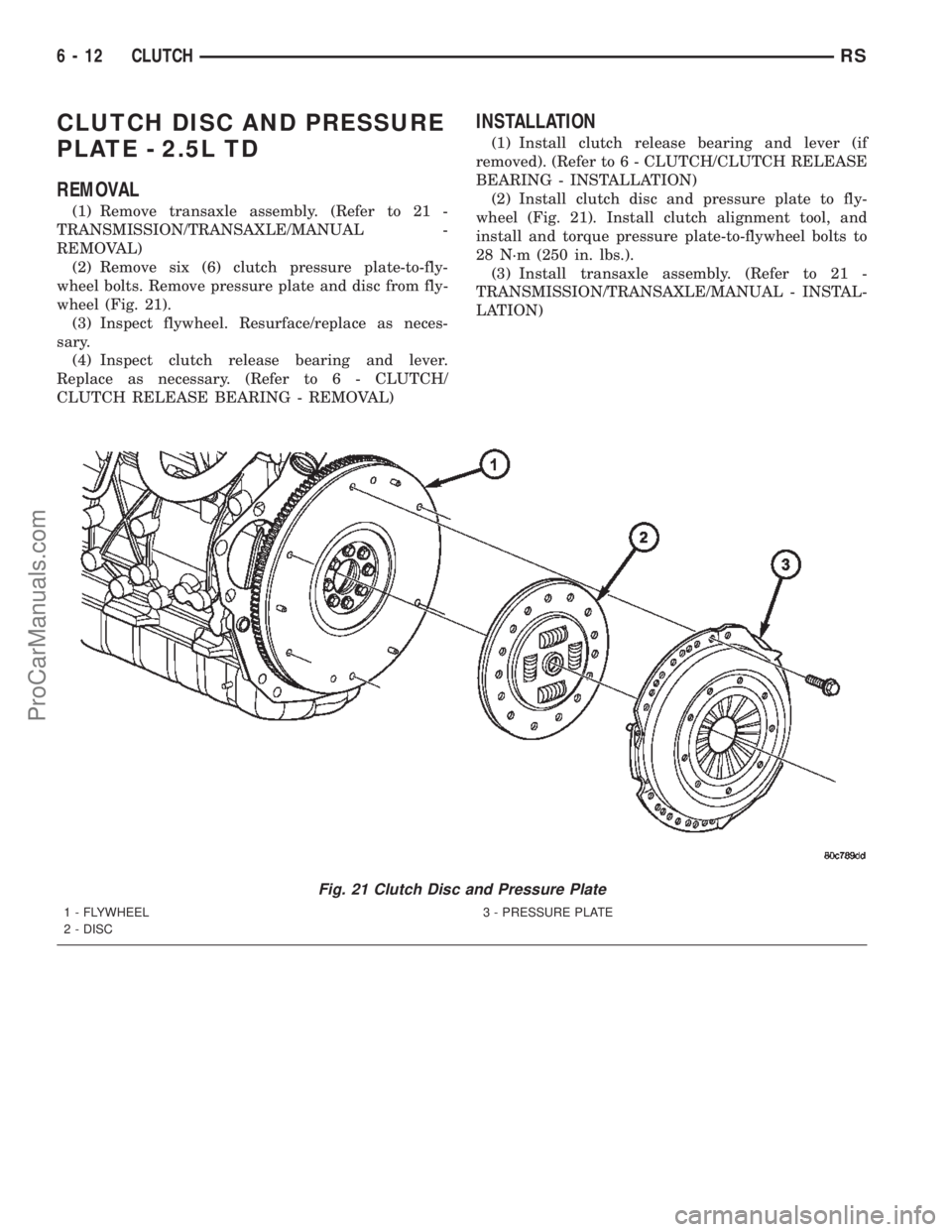
CLUTCH DISC AND PRESSURE
PLATE - 2.5L TD
REMOVAL
(1) Remove transaxle assembly. (Refer to 21 -
TRANSMISSION/TRANSAXLE/MANUAL -
REMOVAL)
(2) Remove six (6) clutch pressure plate-to-fly-
wheel bolts. Remove pressure plate and disc from fly-
wheel (Fig. 21).
(3) Inspect flywheel. Resurface/replace as neces-
sary.
(4) Inspect clutch release bearing and lever.
Replace as necessary. (Refer to 6 - CLUTCH/
CLUTCH RELEASE BEARING - REMOVAL)
INSTALLATION
(1) Install clutch release bearing and lever (if
removed). (Refer to 6 - CLUTCH/CLUTCH RELEASE
BEARING - INSTALLATION)
(2) Install clutch disc and pressure plate to fly-
wheel (Fig. 21). Install clutch alignment tool, and
install and torque pressure plate-to-flywheel bolts to
28 N´m (250 in. lbs.).
(3) Install transaxle assembly. (Refer to 21 -
TRANSMISSION/TRANSAXLE/MANUAL - INSTAL-
LATION)
Fig. 21 Clutch Disc and Pressure Plate
1 - FLYWHEEL
2 - DISC3 - PRESSURE PLATE
6 - 12 CLUTCHRS
ProCarManuals.com
Page 646 of 2399

FRONT WASHER PUMP
MOTOR
REMOVAL
(1) Disconnect and isolate the battery negative
cable.
(2) Remove the engine fresh air housing inside the
engine compartment (Refer to 9 - ENGINE/AIR
INTAKE SYSTEM/AIR CLEANER HOUSING -
REMOVAL).
(3) Disconnect the washer hose at the in-line con-
nector forward of the cowl grille so that the in-line
connector remains with the washer hose from the
fresh air plenum.
(4) Disconnect the washer hose from the hose clip
located on the front fender side shield.
(5) Remove the filler tube screw.
(6) Hoist and support vehicle on hoist or jack
stands.
(7) Remove the right front wheel and tire assembly
(Refer to 22 - TIRES/WHEELS - REMOVAL).
(8) Disconnect the left right front wheelhouse
splash shield and move aside (Refer to 23 - BODY/
EXTERIOR/WHEELHOUSE SPLASH SHIELD -
REMOVAL).
(9) Drain washer fluid from the reservoir and into
a suitable clean container. This can be done by dis-
connecting the windshield washer hose from the
front (outboard) washer pump and allowing the
washer fluid to drain into a container through a tem-
porary jumper hose connected to the front washer
pump.
(10) Disconnect the electrical body harness connec-
tors to the washer pump motors and the fluid level
sensor. Slide the red lock on the connector to the
release position, then, depress the black tab and pull
the connector off the pump or sensor.
(11) Remove the two reservoir mounting screws.
(12) Disconnect the reservoir from the body mount
by raising the reservoir upward slightly and then
down so that the reservoir filler neck and front
washer hose pull through the opening in the front
fender side shield.
(13) Remove pump from reservoir by pulling pump
upper retention tab away from reservoir cavity and
then lifting pump up from mounting grommet. Do
not damage reservoir/pump sealing surface or punc-
ture reservoir during removal.
(14) Remove pump grommet and discard.
INSTALLATION
(1) Use new grommet when installing a new pump
assembly.
(2) Assure pump upper retention tab is pressed
into reservoir slot and that pump is rotated flatagainst the reservoir and that pump connector is fac-
ing up in the fully seated position. Assure the pump
is aligned to and fully seated in the reservoir cavity.
(3) Push filler neck and front washer hose through
the opening in the front fender side shield. Connect
the reservoir to the body mount by lowering the res-
ervoir down.
(4) Install the two reservoir mounting screws.
Torque screws to 8.5 - 11.3 N´m (75 - 100 in. lbs.).
(5) Connect the electrical body harness connectors
to the washer pump motors and the fluid level sen-
sor. Slide the red lock on the connector to the closed
or locked position.
(6) Assure that washer hose is properly routed to
prevent pinching and possible inoperative washers.
(7) Connect the left right front wheelhouse splash
shield and move aside (Refer to 23 - BODY/EXTERI-
OR/WHEELHOUSE SPLASH SHIELD - INSTALLA-
TION).
(8) Install the right front wheel and tire assembly
(Refer to 22 - TIRES/WHEELS - INSTALLATION).
(9) lower vehicle from hoist or jack stands.
(10) Install the filler tube screw. Torque screw to
8.5 - 11.3 N´m (75 - 100 in. lbs.).
(11) Connect the washer hose to the hose clip
located on the front fender side shield.
(12) Connect the washer hose at the in-line con-
nector forward of the cowl grille.
(13) Install the engine fresh air housing inside the
engine compartment (Refer to 9 - ENGINE/AIR
INTAKE SYSTEM/AIR CLEANER HOUSING -
INSTALLATION).
(14) Connect the battery negative cable.
(15) Verify system operation.
FRONT WIPER ARMS
STANDARD PROCEDURE - FRONT WIPER ARM
ALIGNMENT
(1) Verify wiper blade element condition and wiper
arm spring tension. Run wipers in low speed mode
while applying water to the windshield. Observe the
wiper blade that is chattering or skipping across the
windshield. If the wiper element is not rolling over
when the wiper direction reverses, align the wiper
arm. The extension bar portion of the wiper arm
must be twisted in the proper direction to allow the
wiper element to roll over when the direction
reverses.
(2) Place two small adjustable wrenches placed 50
mm (2 in.) apart on the wiper arm extension rod.
(3) Twist the extension rod slightly in the opposite
direction that the element is laying on the wind-
shield while holding the wrench closest to the pivot
stationary.
RSWIPERS/WASHERS8R-9
ProCarManuals.com
Page 1201 of 2399
WARNING: ON VEHICLES EQUIPPED WITH AIR-
BAGS, REFER TO RESTRAINTS BEFORE ATTEMPT-
ING ANY STEERING WHEEL, STEERING COLUMN,
SEAT OR INSTRUMENT PANEL COMPONENT DIAG-
NOSIS OR SERVICE. FAILURE TO TAKE THE
PROPER PRECAUTIONS COULD RESULT IN ACCI-
DENTAL AIRBAG DEPLOYMENT AND POSSIBLE
PERSONAL INJURY.
(1) Check the fused B(+) fuse in the Integrated
Power Module (IPM). If OK, go to Step 2. If not OK,
repair the shorted circuit or component as required
and replace the faulty fuse.
(2) Check for battery voltage at the fused B(+) fuse
in the IPM. If OK, go to Step 3. If not OK, repair the
open fused B(+) circuit to the IPM fuse as required.
(3)
Open the power outlet door. Check for continuity
between the inside circumference of the power outlet
receptacle and a good ground. There should be continu-
ity. If OK, go to Step 4. If not OK, go to Step 5.
(4) Check for battery voltage at the insulated con-
tact located at the back of the power outlet recepta-
cle. If not OK, go to Step 5.
(5) Disconnect and isolate the battery negative
cable. Remove the appropriate bezel. Check for conti-
nuity between the ground circuit cavity of the power
outlet wire harness connector and a good ground.
There should be continuity. If OK, go to Step 6. If not
OK, repair the open ground circuit to ground as
required.
(6) Connect the battery negative cable. Check for
battery voltage at the fused B(+) circuit cavity of the
power outlet wire harness connector. If OK, replace
the faulty power outlet receptacle. If not OK, repair
the open fused B(+) circuit to the IPM fuse as
required.
REMOVAL
(1) Disconnect and isolate the battery negative
cable.
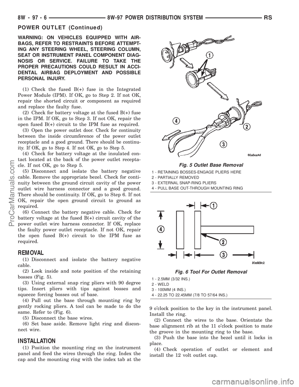
(2) Look inside and note position of the retaining
bosses (Fig. 5).
(3) Using external snap ring pliers with 90 degree
tips. Insert pliers with tips against bosses and
squeeze forcing bosses out of base.
(4) Pull out the base through mounting ring by
gently rocking pliers. A tool can be made to do the
same. Refer to (Fig. 6).
(5) Disconnect the base wires.
(6) Set base aside. Remove light ring and discon-
nect wire.
INSTALLATION
(1) Position the mounting ring on the instrument
panel and feed the wires through the ring. Index the
cap and the mounting ring with the index tab at the9 o'clock position to the key in the instrument panel.
Install the ring.
(2) Connect the wires to the base. Orientate the
base alignment rib at the 11 o'clock position to mate
the groove in the mounting ring to the base.
(3) Push the base into the bezel until it locks in
place.
(4) Check operation of outlet or element and
install the 12 volt outlet cap.
Fig. 5 Outlet Base Removal
1 - RETAINING BOSSES-ENGAGE PLIERS HERE
2 - PARTIALLY REMOVED
3 - EXTERNAL SNAP-RING PLIERS
4 - PULL BASE OUT-THROUGH MOUNTING RING
Fig. 6 Tool For Outlet Removal
1 - 2.5MM (3/32 INS.)
2 - WELD
3 - 100MM (4 INS.)
4 - 22.25 TO 22.45MM (7/8 TO 57/64 INS.)
8W - 97 - 6 8W-97 POWER DISTRIBUTION SYSTEMRS
POWER OUTLET (Continued)
ProCarManuals.com
Page 1323 of 2399
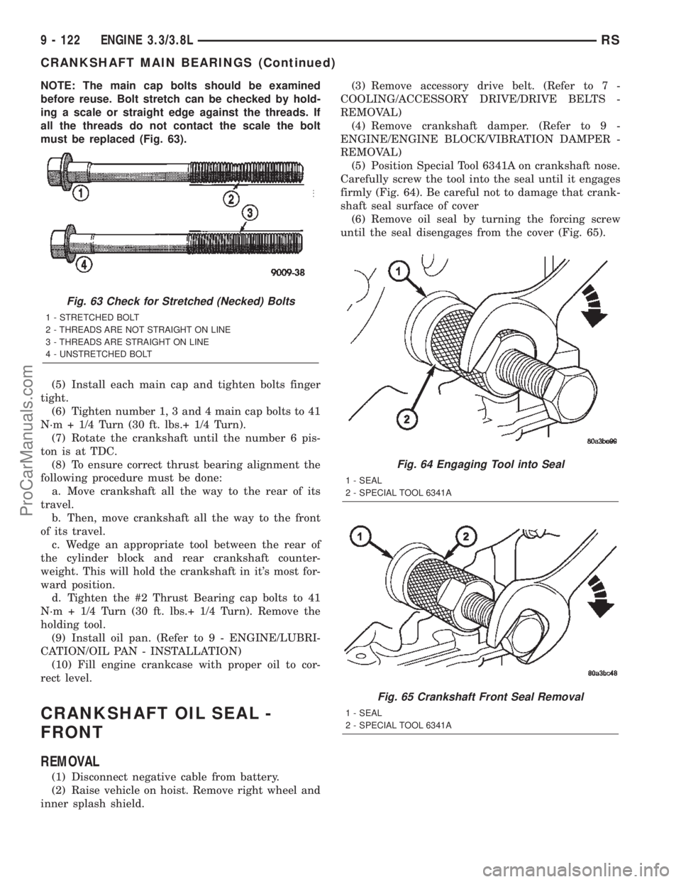
NOTE: The main cap bolts should be examined
before reuse. Bolt stretch can be checked by hold-
ing a scale or straight edge against the threads. If
all the threads do not contact the scale the bolt
must be replaced (Fig. 63).
(5) Install each main cap and tighten bolts finger
tight.
(6) Tighten number 1, 3 and 4 main cap bolts to 41
N´m + 1/4 Turn (30 ft. lbs.+ 1/4 Turn).
(7) Rotate the crankshaft until the number 6 pis-
ton is at TDC.
(8) To ensure correct thrust bearing alignment the
following procedure must be done:
a. Move crankshaft all the way to the rear of its
travel.
b. Then, move crankshaft all the way to the front
of its travel.
c. Wedge an appropriate tool between the rear of
the cylinder block and rear crankshaft counter-
weight. This will hold the crankshaft in it's most for-
ward position.
d. Tighten the #2 Thrust Bearing cap bolts to 41
N´m + 1/4 Turn (30 ft. lbs.+ 1/4 Turn). Remove the
holding tool.
(9) Install oil pan. (Refer to 9 - ENGINE/LUBRI-
CATION/OIL PAN - INSTALLATION)
(10) Fill engine crankcase with proper oil to cor-
rect level.
CRANKSHAFT OIL SEAL -
FRONT
REMOVAL
(1) Disconnect negative cable from battery.
(2) Raise vehicle on hoist. Remove right wheel and
inner splash shield.(3) Remove accessory drive belt. (Refer to 7 -
COOLING/ACCESSORY DRIVE/DRIVE BELTS -
REMOVAL)
(4) Remove crankshaft damper. (Refer to 9 -
ENGINE/ENGINE BLOCK/VIBRATION DAMPER -
REMOVAL)
(5) Position Special Tool 6341A on crankshaft nose.
Carefully screw the tool into the seal until it engages
firmly (Fig. 64). Be careful not to damage that crank-
shaft seal surface of cover
(6) Remove oil seal by turning the forcing screw
until the seal disengages from the cover (Fig. 65).
Fig. 63 Check for Stretched (Necked) Bolts
1 - STRETCHED BOLT
2 - THREADS ARE NOT STRAIGHT ON LINE
3 - THREADS ARE STRAIGHT ON LINE
4 - UNSTRETCHED BOLT
Fig. 64 Engaging Tool into Seal
1 - SEAL
2 - SPECIAL TOOL 6341A
Fig. 65 Crankshaft Front Seal Removal
1 - SEAL
2 - SPECIAL TOOL 6341A
9 - 122 ENGINE 3.3/3.8LRS
CRANKSHAFT MAIN BEARINGS (Continued)
ProCarManuals.com
Page 1376 of 2399
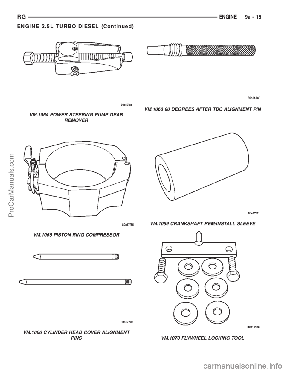
VM.1064 POWER STEERING PUMP GEAR
REMOVER
VM.1065 PISTON RING COMPRESSOR
VM.1066 CYLINDER HEAD COVER ALIGNMENT
PINS
VM.1068 90 DEGREES AFTER TDC ALIGNMENT PIN
VM.1069 CRANKSHAFT REM/INSTALL SLEEVE
VM.1070 FLYWHEEL LOCKING TOOL
RGENGINE9a-15
ENGINE 2.5L TURBO DIESEL (Continued)
ProCarManuals.com
Page 1377 of 2399
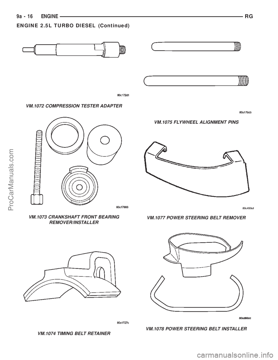
VM.1072 COMPRESSION TESTER ADAPTER
VM.1073 CRANKSHAFT FRONT BEARING
REMOVER/INSTALLER
VM.1074 TIMING BELT RETAINER
VM.1075 FLYWHEEL ALIGNMENT PINS
VM.1077 POWER STEERING BELT REMOVER
VM.1078 POWER STEERING BELT INSTALLER
9a - 16 ENGINERG
ENGINE 2.5L TURBO DIESEL (Continued)
ProCarManuals.com
Page 1392 of 2399
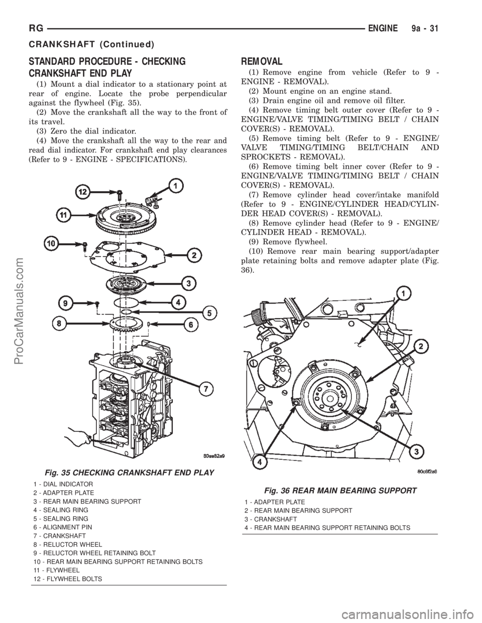
STANDARD PROCEDURE - CHECKING
CRANKSHAFT END PLAY
(1) Mount a dial indicator to a stationary point at
rear of engine. Locate the probe perpendicular
against the flywheel (Fig. 35).
(2) Move the crankshaft all the way to the front of
its travel.
(3) Zero the dial indicator.
(4)
Move the crankshaft all the way to the rear and
read dial indicator. For crankshaft end play clearances
(Refer to 9 - ENGINE - SPECIFICATIONS).
REMOVAL
(1) Remove engine from vehicle (Refer to 9 -
ENGINE - REMOVAL).
(2) Mount engine on an engine stand.
(3) Drain engine oil and remove oil filter.
(4) Remove timing belt outer cover (Refer to 9 -
ENGINE/VALVE TIMING/TIMING BELT / CHAIN
COVER(S) - REMOVAL).
(5) Remove timing belt (Refer to 9 - ENGINE/
VALVE TIMING/TIMING BELT/CHAIN AND
SPROCKETS - REMOVAL).
(6) Remove timing belt inner cover (Refer to 9 -
ENGINE/VALVE TIMING/TIMING BELT / CHAIN
COVER(S) - REMOVAL).
(7) Remove cylinder head cover/intake manifold
(Refer to 9 - ENGINE/CYLINDER HEAD/CYLIN-
DER HEAD COVER(S) - REMOVAL).
(8) Remove cylinder head (Refer to 9 - ENGINE/
CYLINDER HEAD - REMOVAL).
(9) Remove flywheel.
(10) Remove rear main bearing support/adapter
plate retaining bolts and remove adapter plate (Fig.
36).
Fig. 35 CHECKING CRANKSHAFT END PLAY
1 - DIAL INDICATOR
2 - ADAPTER PLATE
3 - REAR MAIN BEARING SUPPORT
4 - SEALING RING
5 - SEALING RING
6 - ALIGNMENT PIN
7 - CRANKSHAFT
8 - RELUCTOR WHEEL
9 - RELUCTOR WHEEL RETAINING BOLT
10 - REAR MAIN BEARING SUPPORT RETAINING BOLTS
11 - FLYWHEEL
12 - FLYWHEEL BOLTSFig. 36 REAR MAIN BEARING SUPPORT
1 - ADAPTER PLATE
2 - REAR MAIN BEARING SUPPORT
3 - CRANKSHAFT
4 - REAR MAIN BEARING SUPPORT RETAINING BOLTS
RGENGINE9a-31
CRANKSHAFT (Continued)
ProCarManuals.com
Page 1414 of 2399

VALVE TIMING
STANDARD PROCEDURE - LOCKING ENGINE
90É AFTER TDC
(1) Disconnect negative battery cable.
(2) Remove starter motor (Refer to 8 - ELECTRI-
CAL/STARTING/STARTER MOTOR - REMOVAL).
(3) Rotate engine untill notch in hub is in the fol-
lowing position (Fig. 84).
(4) Special tool VM.1068 can be install in engine
block as shown at this time (Fig. 85). This will lock
the engine at 90É after TDC.
(5) Remove front wiper unit (Refer to 8 - ELEC-
TRICAL/WIPERS/WASHERS/WIPER MODULE -
REMOVAL).
(6) Remove engine cover (Refer to 9 - ENGINE -
REMOVAL).
(7) Remove plug in cylinder head cover/intake
manifold and insert VM.1053 to lock exhaust cam-
shaft in position (Fig. 86).
(8) Remove generator (Refer to 8 - ELECTRICAL/
CHARGING/GENERATOR - REMOVAL).
Fig. 84 CRANKSHAFT HUB ALIGNMENT
1 - VIBRATION DAMPER/CRANKSHAFT PULLEY
2 - CRANKSHAFT HUB NOTCH
3 - VIBRATION DAMPER/CRANKSHAFT PULLEY TO
CRANKSHAFT HUB BOLTS
Fig. 85 TDC AND 90 DEGREES AFTER TDC
ALIGNMENT PIN LOCATION
1 - ENGINE BLOCK
2 - VM.1051 TDC PIN OR VM.1068 90 DEGREES ATDC PIN
3 - FLYWHEEL
Fig. 86 EXHAUST CAMSHAFT LOCKING PIN
VM.1053
1 - EXHAUST MANIFOLD HEAT SHIELD
2 - EXHAUST CAMSHAFT LOCKING PIN VM.1053
3 - COOLANT TUBE FROM THERMOSTAT HOUSING TO UPPER
RADIATOR HOSE
4 - CYLINDER HEAD COVER/INTAKE MANIFOLD
RGENGINE9a-53
ProCarManuals.com
Page 1416 of 2399
REMOVAL
(1) Disconnect negative battery cable.
(2) Raise vehicle on hoist.
(3) Remove oil pan (Refer to 9 - ENGINE/LUBRI-
CATION/OIL PAN - REMOVAL).
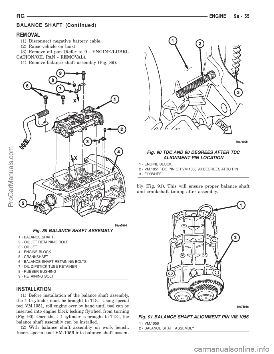
(4) Remove balance shaft assembly (Fig. 89).
INSTALLATION
(1)Before installation of the balance shaft assembly,
the # 1 cylinder must be brought to TDC. Using special
tool VM.1051, roll engine over by hand until tool can be
inserted into engine block locking flywheel from turning
(Fig. 90). Once the # 1 cylinder is brought to TDC, the
balance shaft assembly can be installed.
(2) With balance shaft assembly on work bench.
Insert special tool VM.1056 into balance shaft assem-bly (Fig. 91). This will ensure proper balance shaft
and crankshaft timing after assembly.
Fig. 89 BALANCE SHAFT ASSEMBLY
1 - BALANCE SHAFT
2 - OIL JET RETAINING BOLT
3 - OIL JET
4 - ENGINE BLOCK
5 - CRANKSHAFT
6 - BALANCE SHAFT RETAINING BOLTS
7 - OIL DIPSTICK TUBE RETAINER
8 - RUBBER BUSHING
9 - RETAINING BOLT
Fig. 90 TDC AND 90 DEGREES AFTER TDC
ALIGNMENT PIN LOCATION
1 - ENGINE BLOCK
2 - VM.1051 TDC PIN OR VM.1068 90 DEGREES ATDC PIN
3 - FLYWHEEL
Fig. 91 BALANCE SHAFT ALIGNMENT PIN VM.1056
1 - VM.1056
2 - BALANCE SHAFT ASSEMBLY
RGENGINE9a-55
BALANCE SHAFT (Continued)
ProCarManuals.com