lock CHRYSLER CARAVAN 2002 Owner's Guide
[x] Cancel search | Manufacturer: CHRYSLER, Model Year: 2002, Model line: CARAVAN, Model: CHRYSLER CARAVAN 2002Pages: 2399, PDF Size: 57.96 MB
Page 116 of 2399
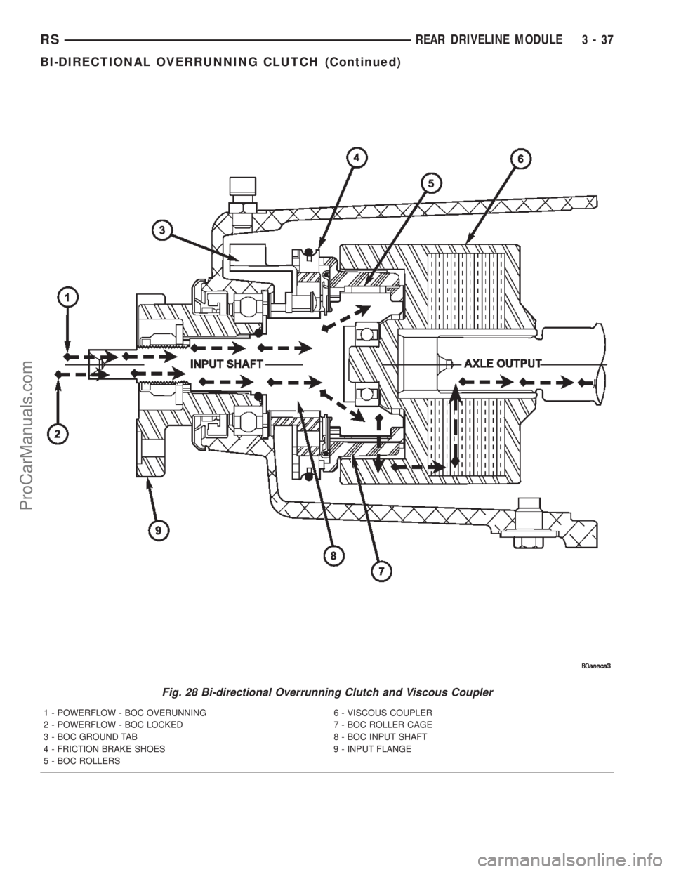
Fig. 28 Bi-directional Overrunning Clutch and Viscous Coupler
1 - POWERFLOW - BOC OVERUNNING 6 - VISCOUS COUPLER
2 - POWERFLOW - BOC LOCKED 7 - BOC ROLLER CAGE
3 - BOC GROUND TAB 8 - BOC INPUT SHAFT
4 - FRICTION BRAKE SHOES 9 - INPUT FLANGE
5 - BOC ROLLERS
RSREAR DRIVELINE MODULE3-37
BI-DIRECTIONAL OVERRUNNING CLUTCH (Continued)
ProCarManuals.com
Page 117 of 2399
OPERATION
In order to achieve all-wheel drive operation in
reverse, the overrunning clutch locking functional direc-
tion must be reversible. The bi-directional overrunning
clutch (BOC) changes the operational mode direction
depending on the propeller shaft direction. The propel-
ler shaft rotates in the clockwise (when viewed from the
front) direction when the vehicle is moving forward,
which indexes the BOC to the forward overrunning
position. When the vehicle is in reverse, the propeller
shaft will rotate counter-clockwise and index the BOC
to the reverse overrunning position.
The BOC acts as a mechanical stator. It is active
(transmitting torque), or it is not active and in over-
running mode (not transmitting torque). This ªall or
nothingº approach to torque transfer would cause a
sudden application of all available power to the rear
wheels, which is not desirable. Therefore it is run in
series with a viscous coupler to smooth, dampen, and
limit the transmission of torque to the rear axle and
to prevent a step style torque input to the rear axle.
STEADY STATE, LOW TO MODERATE SPEED, NO
FRONT WHEEL SLIP, FORWARD DIRECTION
During normal driving conditions, (no wheel slip), the
inner shaft (front axle) and outer race (viscous coupler)
are running at different speeds due to the different gear
ratios between the front and rear differentials. In this
condition, the outer race is always spinning faster (over-
driving between 5-32 rpm) than the inner shaft. When
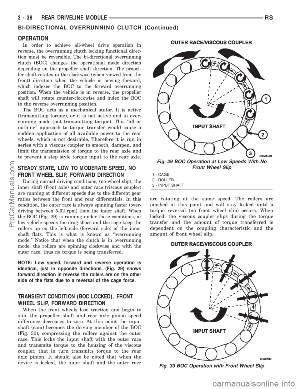
the BOC (Fig. 29) is running under these conditions, at
low vehicle speeds the drag shoes and the cage keep the
rollers up on the left side (forward side) of the inner
shaft flats. This is what is known as ªoverrunning
mode.º Notice that when the clutch is in overrunning
mode, the rollers are spinning clockwise and with the
outer race, thus no torque is being transferred.
NOTE: Low speed, forward and reverse operation is
identical, just in opposite directions. (Fig. 29) shows
forward direction in reverse the rollers are on the other
side of the flats due to a reversal of the cage force.
TRANSIENT CONDITION (BOC LOCKED), FRONT
WHEEL SLIP, FORWARD DIRECTION
When the front wheels lose traction and begin to
slip, the propeller shaft and rear axle pinion speed
difference decreases to zero. At this point the input
shaft (cam) becomes the driving member of the BOC
(Fig. 30), compressing the rollers against the outer
race. This locks the input shaft with the outer race
and transmits torque to the housing of the viscous
coupler, that in turn transmits torque to the rear
axle pinion. It should also be noted that when the
device is locked, the inner shaft and the outer raceare rotating at the same speed. The rollers are
pinched at this point and will stay locked until a
torque reversal (no front wheel slip) occurs. When
locked, the viscous coupler slips during the torque
transfer and the amount of torque transferred is
dependent on the coupling characteristic and the
amount of front wheel slip.
Fig. 29 BOC Operation at Low Speeds With No
Front Wheel Slip
1 - CAGE
2 - ROLLER
3 - INPUT SHAFT
Fig. 30 BOC Operation with Front Wheel Slip
3 - 38 REAR DRIVELINE MODULERS
BI-DIRECTIONAL OVERRUNNING CLUTCH (Continued)
ProCarManuals.com
Page 118 of 2399

STEADY STATE, HIGH SPEED, NO WHEEL SLIP
The roller cage positions the rollers on the input shaft
flats during low and high speed overrunning and during
initial BOC lockup. The roller cage is rotating at input
shaft (propeller shaft) speed at all times. At low speeds,
the friction shoes (Fig. 31) are pressed against the fric-
tion ground via the garter spring (Fig. 32), creating a
drag force on the roller cage. The drag force positions
the cage, which in turn positions the rollers to one side
of the flat. The direction of this drag force (position of
the roller) is dependent on the input (propeller shaft)
rotational direction. Since the rollers are always in con-
tact with the outer race, due to centrifugal forces, the
rollers want to follow the outer race due to drag. During
overrunning operation, the outer race is rotating faster
than the input; causing the rollers to want to traverse
the flat from one side to the other. During low speeds,
the brake shoes counteract this effect. To avoid exces-
sive wear, the ground shoes are designed to lift off from
the friction ground due to centrifugal forces at higher
rotational speeds.
To keep the rollers in the overrunning position and
avoid undesired9high speed lockup9, a high speed
latch (Fig. 33) positions the cage before the ground
shoes lift off. A further explanation of the high speed
effects follows as well. Utilizing only the friction
shoes approach means that at high speed the
required ground shoe drag torque would cause exces-
sive brake shoe wear or the roller will begin tomigrate to the opposite side of the flat due to the
drag force of the outer race. This would result in sys-
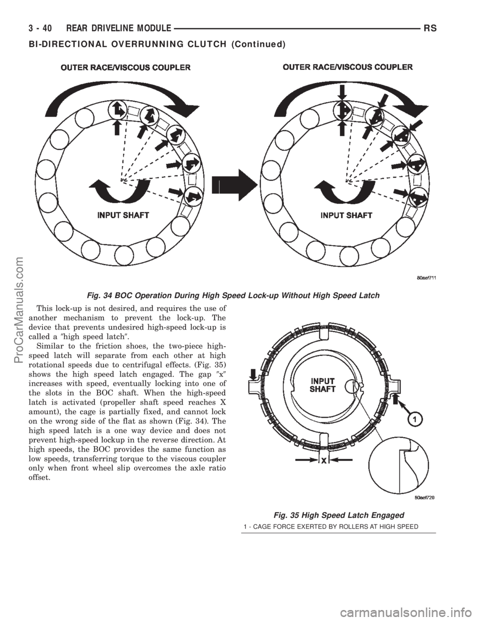
tem lock-up. (Fig. 34) shows the BOC as it crosses
the speed where the brake shoe force is overcome by
the roller drag on the outer race. Notice that the
roller is locking up on the opposite side of the flat
and the cage supplies no force on the rollers.
Fig. 31 Front View of BOC
1 - GARTER SPRING
2 - FRICTION BRAKE SHOES
3 - FRICTION GROUND CONNECTED TO GROUND TAB
4 - INPUT SHAFT
Fig. 32 Location of the Grounding Element
1 - DIFFERENTIAL HOUSING
2 - GROUND TAB
3 - GARTER SPRING
Fig. 33 BOC High Speed Latch (Not Engaged)
1 - TOOTH (TWO PLACES)
2 - GARTER SPRING
3 - TABS AT BOTH ENDS FIT INTO SLOTS IN CAGE
4 - TWO PART DESIGN
RSREAR DRIVELINE MODULE3-39
BI-DIRECTIONAL OVERRUNNING CLUTCH (Continued)
ProCarManuals.com
Page 119 of 2399
This lock-up is not desired, and requires the use of
another mechanism to prevent the lock-up. The
device that prevents undesired high-speed lock-up is
called a9high speed latch9.
Similar to the friction shoes, the two-piece high-
speed latch will separate from each other at high
rotational speeds due to centrifugal effects. (Fig. 35)
shows the high speed latch engaged. The gap9x9
increases with speed, eventually locking into one of
the slots in the BOC shaft. When the high-speed
latch is activated (propeller shaft speed reaches X
amount), the cage is partially fixed, and cannot lock
on the wrong side of the flat as shown (Fig. 34). The
high speed latch is a one way device and does not
prevent high-speed lockup in the reverse direction. At
high speeds, the BOC provides the same function as
low speeds, transferring torque to the viscous coupler
only when front wheel slip overcomes the axle ratio
offset.
Fig. 34 BOC Operation During High Speed Lock-up Without High Speed Latch
Fig. 35 High Speed Latch Engaged
1 - CAGE FORCE EXERTED BY ROLLERS AT HIGH SPEED
3 - 40 REAR DRIVELINE MODULERS
BI-DIRECTIONAL OVERRUNNING CLUTCH (Continued)
ProCarManuals.com
Page 120 of 2399

At high speed, the rollers are forced outward to the
outer race because of centrifugal force. At high
speeds, the friction shoes can no longer prevent lock-
up. When the teeth on the high-speed latch engage
into the input shaft, it keeps the rollers centered
above the flats because the tabs on the latch are
locked into the cage. (Fig. 36) shows the roller config-
uration with the High-Speed Latch engaged.
On the BOC shaft, the high speed latch teeth lock
up in the grooved areas, shown in (Fig. 37), when the
turning speed reaches the critical value. (Fig. 37)
also shows the outer race/viscous coupler. Notice the
surface (outer race) the rollers mate against when
transferring torque.
DIFFERENTIAL ASSEMBLY
DESCRIPTION
The differential gear system divides the torque
between the axle shafts. It allows the axle shafts to
rotate at different speeds when turning corners.
Each differential side gear is splined to an axle
shaft. The pinion gears are mounted on a pinion
mate shaft and are free to rotate on the shaft. The
pinion gear is fitted in a bore in the differential case
and is positioned at a right angle to the axle shafts.
OPERATION
In operation, power flow occurs as follows:
²The pinion gear rotates the ring gear²The ring gear (bolted to the differential case)
rotates the case
²The differential pinion gears (mounted on the
pinion mate shaft in the case) rotate the side gears
²The side gears (splined to the axle shafts) rotate
the shafts
During straight-ahead driving, the differential pin-
ion gears do not rotate on the pinion mate shaft. This
occurs because input torque applied to the gears is
divided and distributed equally between the two side
gears. As a result, the pinion gears revolve with the
pinion mate shaft but do not rotate around it (Fig.
38).
Fig. 36 BOC Operation at High Speed with High
Speed Latch
Fig. 37 BOC Input Shaft
1 - GROOVED AREA (2 LOCATIONS)
2 - ROLLER MATING SURFACE
Fig. 38 Differential OperationÐStraight Ahead
Driving
1 - IN STRAIGHT AHEAD DRIVING EACH WHEEL ROTATES AT
100% OF CASE SPEED
2 - PINION GEAR
3 - SIDE GEAR
4 - PINION GEARS ROTATE WITH CASE
RSREAR DRIVELINE MODULE3-41
BI-DIRECTIONAL OVERRUNNING CLUTCH (Continued)
ProCarManuals.com
Page 123 of 2399

VISCOUS COUPLER
DESCRIPTION
The heart of the all-wheel drive system is the
inter-axle viscous coupling and bi-directional over-
running clutch. Under normal driving the vehicle
retains predominantly front wheel drive characteris-
tics. The all-wheel drive takes effect when the front
wheels start to slip. Under normal level road,
straight line driving, 100% of the torque is allocated
to the front wheels. The viscous coupler allows more
torque to the rear wheels in accordance with the
amount of slippage at the front wheels. The variable
torque distribution is automatic with no driver
inputs required.
OPERATION
The viscous coupler (Fig. 46) is a housing nearly
filled with a high viscosity silicone liquid and thin
metal plates alternately splined to an inner and
outer drum. The viscous coupler provides torque in
the following modes:
²Shear mode (normal operation)
²Hump mode (locked mode)The inner plates are slotted around the radius and
the outer plates have holes in them. In the shear
mode (normal operation), the plates are evenly
spaced and the torque is created by the shearing of
the plates through the fluid and 90-100% of the
torque is applied to the rear axle. During the shear
mode, a fluid flow pattern is created from this design
(holes and slots). This fluid flow causes high pressure
on each side of each pair of plates and low pressure
between each pair of plates.
When a high speed difference (shear) occurs
because of loss of traction (one axle spinning faster
than the other), the silicone fluid expands as it heats
from this shearing. When the silicone expands to fill
the viscous coupler completely, this pressure differ-
ence is high enough to squeeze each pair of plates
together. The resulting hump torque is up to 8 times
higher than the shear torque. When the viscous cou-
pler is in the hump mode, it does not lock the axles
(undifferentiated 4-Wheel Drive). It controls the
amount of slippage while delivering maximum power
to the axle having greatest traction. Once the speed
difference equalizes the fluid and plates cool down
and the viscous coupler goes back to the shear mode.
3 - 44 REAR DRIVELINE MODULERS
ProCarManuals.com
Page 124 of 2399
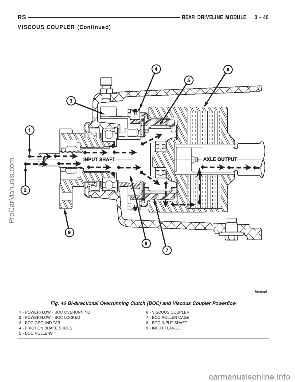
Fig. 46 Bi-directional Overrunning Clutch (BOC) and Viscous Coupler Powerflow
1 - POWERFLOW - BOC OVERUNNING 6 - VISCOUS COUPLER
2 - POWERFLOW - BOC LOCKED 7 - BOC ROLLER CAGE
3 - BOC GROUND TAB 8 - BOC INPUT SHAFT
4 - FRICTION BRAKE SHOES 9 - INPUT FLANGE
5 - BOC ROLLERS
RSREAR DRIVELINE MODULE3-45
VISCOUS COUPLER (Continued)
ProCarManuals.com
Page 127 of 2399

OUTPUT FLANGE SEAL
REMOVAL
(1) Raise vehicle on hoist.
(2) Remove rear halfshaft inner joint at differen-
tial output flange (Fig. 54).
(3) Using two screwdrivers and wood blocks to pro-
tect differential housing casting, pry output flange
out of differential (Fig. 55).
(4) Use suitable screwdriver to remove output
flange seal (Fig. 56).
Fig. 54 Inner Half Shaft Bolts
1 - SHAFT
2 - FLANGE
Fig. 55 Output Flange Removal
1 - WOOD BLOCK
2 - PRYBAR
3 - OUTPUT SHAFT
4 - PRYBAR
5 - WOOD BLOCK
6 - DIFFERENTIAL CASE
Fig. 56 Output Flange Seal Removal
1 - OUTPUT FLANGE SEAL
2 - SCREWDRIVER
3 - 48 REAR DRIVELINE MODULERS
ProCarManuals.com
Page 131 of 2399

DISC BRAKE CALIPER - FRONT
REMOVAL
REMOVAL - FRONT DISC BRAKE CALIPER
(DISC/DISC BRAKES)..................26
REMOVAL - FRONT DISC BRAKE CALIPER
(DISC/DRUM BRAKES).................26
DISASSEMBLY
DISASSEMBLY - CALIPER GUIDE PIN
BUSHINGS (DISC/DISC BRAKES).........27
DISASSEMBLY - CALIPER PISTON AND
SEAL...............................27
CLEANING - CALIPER...................28
INSPECTION - CALIPER..................28
ASSEMBLY
ASSEMBLY - CALIPER GUIDE PIN
BUSHINGS (DISC/DISC BRAKES).........28
ASSEMBLY - CALIPER PISTON AND SEAL . . 28
INSTALLATION
INSTALLATION - FRONT DISC BRAKE
CALIPER (DISC/DISC BRAKES)...........29
INSTALLATION - FRONT DISC BRAKE
CALIPER (DISC/DRUM BRAKES)..........30
DISC BRAKE CALIPER - REAR
REMOVAL - REAR DISC BRAKE CALIPER....30
DISASSEMBLY - CALIPER PISTON AND SEAL . 31
CLEANING - CALIPER...................32
INSPECTION - CALIPER..................32
ASSEMBLY - CALIPER PISTON AND SEAL . . . 32
INSTALLATION - REAR DISC BRAKE CALIPER . 33
DISC BRAKE CALIPER ADAPTER
REMOVAL - FRONT DISC BRAKE CALIPER
ADAPTER...........................34
INSTALLATION - FRONT DISC BRAKE
CALIPER ADAPTER....................34
DISC BRAKE CALIPER GUIDE PINS
REMOVAL - DISC BRAKE CALIPER GUIDE
PINS (DISC/DRUM BRAKES).............34
INSTALLATION - DISC BRAKE CALIPER
GUIDE PINS (DISC/DRUM BRAKES).......34
DRUM
REMOVAL.............................35
INSTALLATION.........................35
FLUID
DIAGNOSIS AND TESTING - BRAKE FLUID
CONTAMINATION.....................35
STANDARD PROCEDURE - BRAKE FLUID
LEVEL CHECKING.....................35
SPECIFICATIONS
BRAKE FLUID........................35
JUNCTION BLOCK
DESCRIPTION - NON-ABS JUNCTION BLOCK . 36
OPERATION - NON-ABS JUNCTION BLOCK . . 36
REMOVAL - NON-ABS JUNCTION BLOCK....36
INSTALLATION - NON-ABS JUNCTION BLOCK . 36
MASTER CYLINDER
DESCRIPTION
DESCRIPTION........................37DESCRIPTION - RHD..................38
OPERATION...........................38
STANDARD PROCEDURE - MASTER
CYLINDER BLEEDING..................38
REMOVAL
REMOVAL - LHD......................39
REMOVAL - RHD......................40
DISASSEMBLY - MASTER CYLINDER (FLUID
RESERVOIR).........................40
ASSEMBLY - MASTER CYLINDER (FLUID
RESERVOIR).........................41
INSTALLATION
INSTALLATION - LHD..................41
INSTALLATION - RHD..................42
PEDAL - ADJUSTABLE
DESCRIPTION.........................42
OPERATION...........................42
DIAGNOSIS AND TESTING - ADJUSTABLE
PEDAL SYSTEM......................43
REMOVAL.............................43
INSTALLATION.........................45
PEDAL TORQUE SHAFT - RHD
REMOVAL.............................47
INSTALLATION.........................47
POWER BRAKE BOOSTER
DESCRIPTION.........................48
OPERATION...........................49
DIAGNOSIS AND TESTING - POWER BRAKE
BOOSTER...........................49
REMOVAL
REMOVAL - LHD......................50
REMOVAL - RHD......................52
INSTALLATION
INSTALLATION - LHD..................53
INSTALLATION - RHD..................55
PROPORTIONING VALVE
DESCRIPTION - PROPORTIONING VALVE
(HEIGHT SENSING)....................56
OPERATION - PROPORTIONING VALVE
(HEIGHT SENSING)....................57
DIAGNOSIS AND TESTING -
PROPORTIONING VALVE (HEIGHT
SENSING)...........................57
REMOVAL - PROPORTIONING VALVE
(HEIGHT SENSING)....................58
INSTALLATION - PROPORTIONING VALVE
(HEIGHT SENSING)....................59
ROTOR
DIAGNOSIS AND TESTING - BRAKE ROTOR . . 59
STANDARD PROCEDURE - BRAKE ROTOR
MACHINING..........................61
REMOVAL - FRONT BRAKE ROTOR........62
INSTALLATION - FRONT BRAKE ROTOR.....62
SPECIFICATIONS
BRAKE ROTOR.......................63
BRAKE ROTOR - EXPORT..............63
5 - 2 BRAKES - BASERS
ProCarManuals.com
Page 132 of 2399
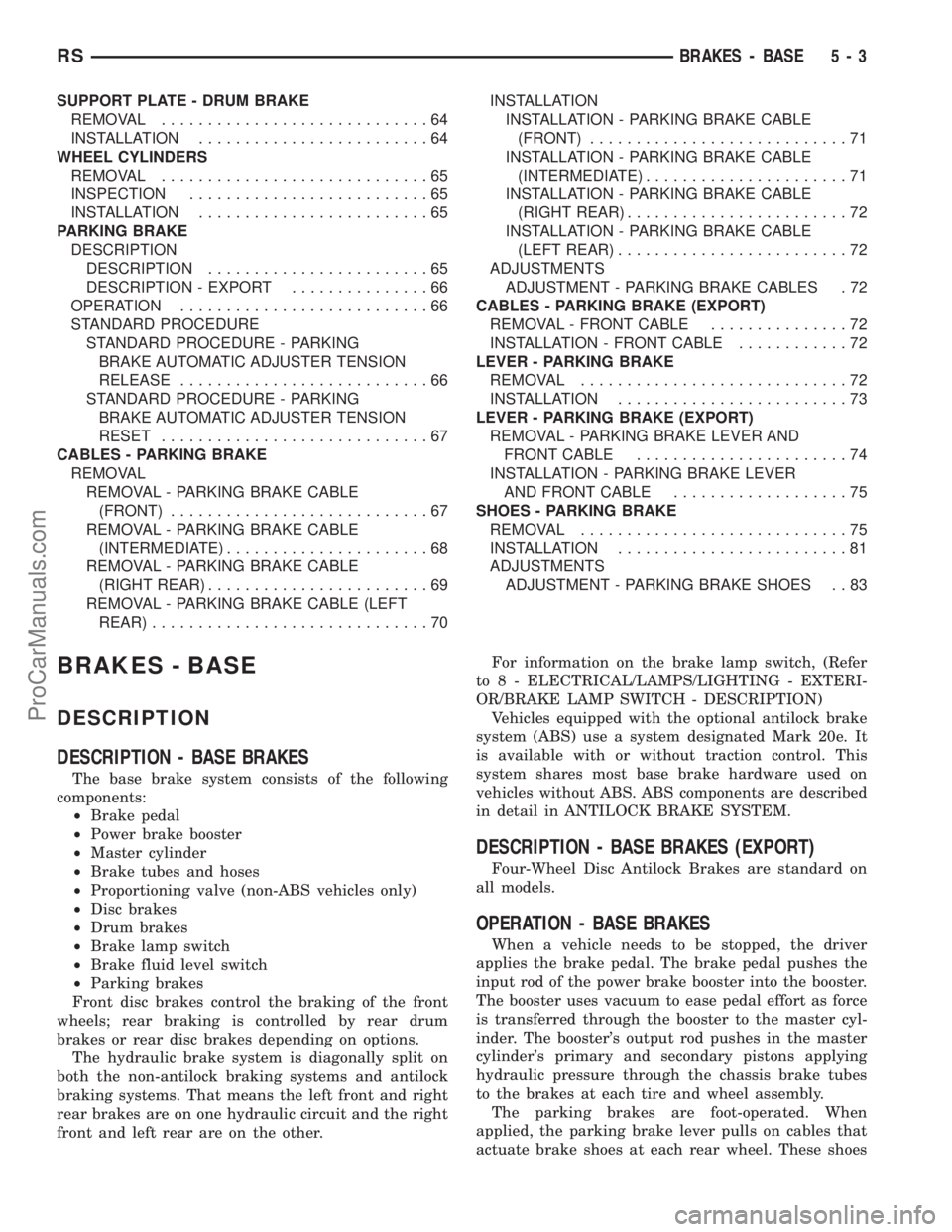
SUPPORT PLATE - DRUM BRAKE
REMOVAL.............................64
INSTALLATION.........................64
WHEEL CYLINDERS
REMOVAL.............................65
INSPECTION..........................65
INSTALLATION.........................65
PARKING BRAKE
DESCRIPTION
DESCRIPTION........................65
DESCRIPTION - EXPORT...............66
OPERATION...........................66
STANDARD PROCEDURE
STANDARD PROCEDURE - PARKING
BRAKE AUTOMATIC ADJUSTER TENSION
RELEASE...........................66
STANDARD PROCEDURE - PARKING
BRAKE AUTOMATIC ADJUSTER TENSION
RESET.............................67
CABLES - PARKING BRAKE
REMOVAL
REMOVAL - PARKING BRAKE CABLE
(FRONT)............................67
REMOVAL - PARKING BRAKE CABLE
(INTERMEDIATE)......................68
REMOVAL - PARKING BRAKE CABLE
(RIGHT REAR)........................69
REMOVAL - PARKING BRAKE CABLE (LEFT
REAR)..............................70INSTALLATION
INSTALLATION - PARKING BRAKE CABLE
(FRONT)............................71
INSTALLATION - PARKING BRAKE CABLE
(INTERMEDIATE)......................71
INSTALLATION - PARKING BRAKE CABLE
(RIGHT REAR)........................72
INSTALLATION - PARKING BRAKE CABLE
(LEFT REAR).........................72
ADJUSTMENTS
ADJUSTMENT - PARKING BRAKE CABLES . 72
CABLES - PARKING BRAKE (EXPORT)
REMOVAL - FRONT CABLE...............72
INSTALLATION - FRONT CABLE............72
LEVER - PARKING BRAKE
REMOVAL.............................72
INSTALLATION.........................73
LEVER - PARKING BRAKE (EXPORT)
REMOVAL - PARKING BRAKE LEVER AND
FRONT CABLE.......................74
INSTALLATION - PARKING BRAKE LEVER
AND FRONT CABLE...................75
SHOES - PARKING BRAKE
REMOVAL.............................75
INSTALLATION.........................81
ADJUSTMENTS
ADJUSTMENT - PARKING BRAKE SHOES . . 83
BRAKES - BASE
DESCRIPTION
DESCRIPTION - BASE BRAKES
The base brake system consists of the following
components:
²Brake pedal
²Power brake booster
²Master cylinder
²Brake tubes and hoses
²Proportioning valve (non-ABS vehicles only)
²Disc brakes
²Drum brakes
²Brake lamp switch
²Brake fluid level switch
²Parking brakes
Front disc brakes control the braking of the front
wheels; rear braking is controlled by rear drum
brakes or rear disc brakes depending on options.
The hydraulic brake system is diagonally split on
both the non-antilock braking systems and antilock
braking systems. That means the left front and right
rear brakes are on one hydraulic circuit and the right
front and left rear are on the other.For information on the brake lamp switch, (Refer
to 8 - ELECTRICAL/LAMPS/LIGHTING - EXTERI-
OR/BRAKE LAMP SWITCH - DESCRIPTION)
Vehicles equipped with the optional antilock brake
system (ABS) use a system designated Mark 20e. It
is available with or without traction control. This
system shares most base brake hardware used on
vehicles without ABS. ABS components are described
in detail in ANTILOCK BRAKE SYSTEM.
DESCRIPTION - BASE BRAKES (EXPORT)
Four-Wheel Disc Antilock Brakes are standard on
all models.
OPERATION - BASE BRAKES
When a vehicle needs to be stopped, the driver
applies the brake pedal. The brake pedal pushes the
input rod of the power brake booster into the booster.
The booster uses vacuum to ease pedal effort as force
is transferred through the booster to the master cyl-
inder. The booster's output rod pushes in the master
cylinder's primary and secondary pistons applying
hydraulic pressure through the chassis brake tubes
to the brakes at each tire and wheel assembly.
The parking brakes are foot-operated. When
applied, the parking brake lever pulls on cables that
actuate brake shoes at each rear wheel. These shoes
RSBRAKES - BASE5-3
ProCarManuals.com