lock CHRYSLER CARAVAN 2002 Service Manual
[x] Cancel search | Manufacturer: CHRYSLER, Model Year: 2002, Model line: CARAVAN, Model: CHRYSLER CARAVAN 2002Pages: 2399, PDF Size: 57.96 MB
Page 1414 of 2399

VALVE TIMING
STANDARD PROCEDURE - LOCKING ENGINE
90É AFTER TDC
(1) Disconnect negative battery cable.
(2) Remove starter motor (Refer to 8 - ELECTRI-
CAL/STARTING/STARTER MOTOR - REMOVAL).
(3) Rotate engine untill notch in hub is in the fol-
lowing position (Fig. 84).
(4) Special tool VM.1068 can be install in engine
block as shown at this time (Fig. 85). This will lock
the engine at 90É after TDC.
(5) Remove front wiper unit (Refer to 8 - ELEC-
TRICAL/WIPERS/WASHERS/WIPER MODULE -
REMOVAL).
(6) Remove engine cover (Refer to 9 - ENGINE -
REMOVAL).
(7) Remove plug in cylinder head cover/intake
manifold and insert VM.1053 to lock exhaust cam-
shaft in position (Fig. 86).
(8) Remove generator (Refer to 8 - ELECTRICAL/
CHARGING/GENERATOR - REMOVAL).
Fig. 84 CRANKSHAFT HUB ALIGNMENT
1 - VIBRATION DAMPER/CRANKSHAFT PULLEY
2 - CRANKSHAFT HUB NOTCH
3 - VIBRATION DAMPER/CRANKSHAFT PULLEY TO
CRANKSHAFT HUB BOLTS
Fig. 85 TDC AND 90 DEGREES AFTER TDC
ALIGNMENT PIN LOCATION
1 - ENGINE BLOCK
2 - VM.1051 TDC PIN OR VM.1068 90 DEGREES ATDC PIN
3 - FLYWHEEL
Fig. 86 EXHAUST CAMSHAFT LOCKING PIN
VM.1053
1 - EXHAUST MANIFOLD HEAT SHIELD
2 - EXHAUST CAMSHAFT LOCKING PIN VM.1053
3 - COOLANT TUBE FROM THERMOSTAT HOUSING TO UPPER
RADIATOR HOSE
4 - CYLINDER HEAD COVER/INTAKE MANIFOLD
RGENGINE9a-53
ProCarManuals.com
Page 1415 of 2399
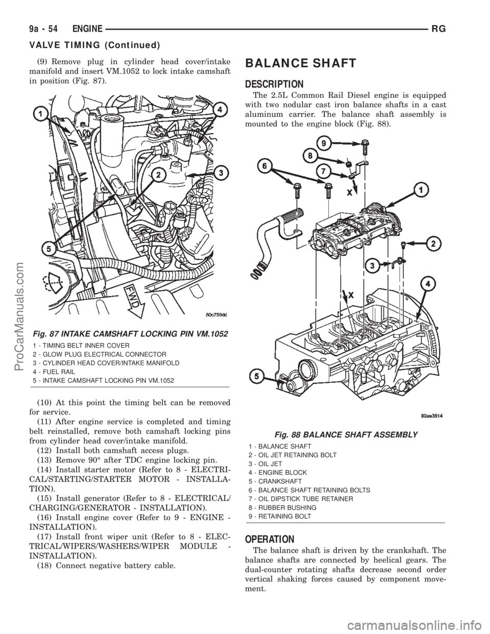
(9) Remove plug in cylinder head cover/intake
manifold and insert VM.1052 to lock intake camshaft
in position (Fig. 87).
(10) At this point the timing belt can be removed
for service.
(11) After engine service is completed and timing
belt reinstalled, remove both camshaft locking pins
from cylinder head cover/intake manifold.
(12) Install both camshaft access plugs.
(13) Remove 90É after TDC engine locking pin.
(14) Install starter motor (Refer to 8 - ELECTRI-
CAL/STARTING/STARTER MOTOR - INSTALLA-
TION).
(15) Install generator (Refer to 8 - ELECTRICAL/
CHARGING/GENERATOR - INSTALLATION).
(16) Install engine cover (Refer to 9 - ENGINE -
INSTALLATION).
(17) Install front wiper unit (Refer to 8 - ELEC-
TRICAL/WIPERS/WASHERS/WIPER MODULE -
INSTALLATION).
(18) Connect negative battery cable.BALANCE SHAFT
DESCRIPTION
The 2.5L Common Rail Diesel engine is equipped
with two nodular cast iron balance shafts in a cast
aluminum carrier. The balance shaft assembly is
mounted to the engine block (Fig. 88).
OPERATION
The balance shaft is driven by the crankshaft. The
balance shafts are connected by heelical gears. The
dual-counter rotating shafts decrease second order
vertical shaking forces caused by component move-
ment.
Fig. 87 INTAKE CAMSHAFT LOCKING PIN VM.1052
1 - TIMING BELT INNER COVER
2 - GLOW PLUG ELECTRICAL CONNECTOR
3 - CYLINDER HEAD COVER/INTAKE MANIFOLD
4 - FUEL RAIL
5 - INTAKE CAMSHAFT LOCKING PIN VM.1052
Fig. 88 BALANCE SHAFT ASSEMBLY
1 - BALANCE SHAFT
2 - OIL JET RETAINING BOLT
3 - OIL JET
4 - ENGINE BLOCK
5 - CRANKSHAFT
6 - BALANCE SHAFT RETAINING BOLTS
7 - OIL DIPSTICK TUBE RETAINER
8 - RUBBER BUSHING
9 - RETAINING BOLT
9a - 54 ENGINERG
VALVE TIMING (Continued)
ProCarManuals.com
Page 1416 of 2399
REMOVAL
(1) Disconnect negative battery cable.
(2) Raise vehicle on hoist.
(3) Remove oil pan (Refer to 9 - ENGINE/LUBRI-
CATION/OIL PAN - REMOVAL).
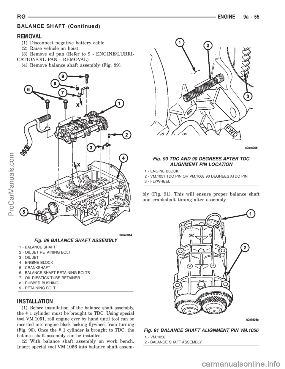
(4) Remove balance shaft assembly (Fig. 89).
INSTALLATION
(1)Before installation of the balance shaft assembly,
the # 1 cylinder must be brought to TDC. Using special
tool VM.1051, roll engine over by hand until tool can be
inserted into engine block locking flywheel from turning
(Fig. 90). Once the # 1 cylinder is brought to TDC, the
balance shaft assembly can be installed.
(2) With balance shaft assembly on work bench.
Insert special tool VM.1056 into balance shaft assem-bly (Fig. 91). This will ensure proper balance shaft
and crankshaft timing after assembly.
Fig. 89 BALANCE SHAFT ASSEMBLY
1 - BALANCE SHAFT
2 - OIL JET RETAINING BOLT
3 - OIL JET
4 - ENGINE BLOCK
5 - CRANKSHAFT
6 - BALANCE SHAFT RETAINING BOLTS
7 - OIL DIPSTICK TUBE RETAINER
8 - RUBBER BUSHING
9 - RETAINING BOLT
Fig. 90 TDC AND 90 DEGREES AFTER TDC
ALIGNMENT PIN LOCATION
1 - ENGINE BLOCK
2 - VM.1051 TDC PIN OR VM.1068 90 DEGREES ATDC PIN
3 - FLYWHEEL
Fig. 91 BALANCE SHAFT ALIGNMENT PIN VM.1056
1 - VM.1056
2 - BALANCE SHAFT ASSEMBLY
RGENGINE9a-55
BALANCE SHAFT (Continued)
ProCarManuals.com
Page 1417 of 2399
(3) Install balance shaft assembly and retaining
bolts (Fig. 89). Torque bolts to 32.4N´m.
(4) Install oil pan (Refer to 9 - ENGINE/LUBRI-
CATION/OIL PAN - INSTALLATION).
(5) Refill engine oil to proper level.
(6) Connect negative battery cable.
TIMING BELT / CHAIN
COVER(S)
REMOVAL
REMOVAL - TIMING BELT OUTER COVER
(1) Disconnect negative battery cable.
(2) Remove engine cover (Refer to 9 - ENGINE -
REMOVAL).
(3) Remove air cleaner housing.
(4) Support engine and remove right engine mount
and bracket.
(5) Remove power steering belt (Refer to 7 -
COOLING/ACCESSORY DRIVE/DRIVE BELTS -
REMOVAL).
(6) Remove accessory drive belt (Refer to 7 -
COOLING/ACCESSORY DRIVE/DRIVE BELTS -
REMOVAL).
(7) Remove vibration damper (Refer to 9 -
ENGINE/ENGINE BLOCK/VIBRATION DAMPER -
REMOVAL).
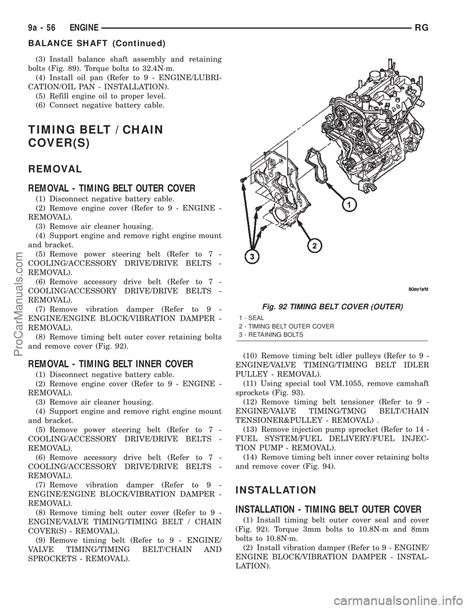
(8) Remove timing belt outer cover retaining bolts
and remove cover (Fig. 92).
REMOVAL - TIMING BELT INNER COVER
(1) Disconnect negative battery cable.
(2) Remove engine cover (Refer to 9 - ENGINE -
REMOVAL).
(3) Remove air cleaner housing.
(4) Support engine and remove right engine mount
and bracket.
(5) Remove power steering belt (Refer to 7 -
COOLING/ACCESSORY DRIVE/DRIVE BELTS -
REMOVAL).
(6) Remove accessory drive belt (Refer to 7 -
COOLING/ACCESSORY DRIVE/DRIVE BELTS -
REMOVAL).
(7) Remove vibration damper (Refer to 9 -
ENGINE/ENGINE BLOCK/VIBRATION DAMPER -
REMOVAL).
(8) Remove timing belt outer cover (Refer to 9 -
ENGINE/VALVE TIMING/TIMING BELT / CHAIN
COVER(S) - REMOVAL).
(9) Remove timing belt (Refer to 9 - ENGINE/
VALVE TIMING/TIMING BELT/CHAIN AND
SPROCKETS - REMOVAL).(10) Remove timing belt idler pulleys (Refer to 9 -
ENGINE/VALVE TIMING/TIMING BELT IDLER
PULLEY - REMOVAL).
(11) Using special tool VM.1055, remove camshaft
sprockets (Fig. 93).
(12) Remove timing belt tensioner (Refer to 9 -
ENGINE/VALVE TIMING/TMNG BELT/CHAIN
TENSIONER&PULLEY - REMOVAL) .
(13) Remove injection pump sprocket (Refer to 14 -
FUEL SYSTEM/FUEL DELIVERY/FUEL INJEC-
TION PUMP - REMOVAL).
(14) Remove timing belt inner cover retaining bolts
and remove cover (Fig. 94).
INSTALLATION
INSTALLATION - TIMING BELT OUTER COVER
(1) Install timing belt outer cover seal and cover
(Fig. 92). Torque 3mm bolts to 10.8N´m and 8mm
bolts to 10.8N´m.
(2) Install vibration damper (Refer to 9 - ENGINE/
ENGINE BLOCK/VIBRATION DAMPER - INSTAL-
LATION).
Fig. 92 TIMING BELT COVER (OUTER)
1 - SEAL
2 - TIMING BELT OUTER COVER
3 - RETAINING BOLTS
9a - 56 ENGINERG
BALANCE SHAFT (Continued)
ProCarManuals.com
Page 1419 of 2399
(9) Install vibration damper (Refer to 9 - ENGINE/
ENGINE BLOCK/VIBRATION DAMPER - INSTAL-
LATION).
(10) Install accessory drive belt (Refer to 7 -
COOLING/ACCESSORY DRIVE/DRIVE BELTS -
INSTALLATION).
(11) Install power steering belt (Refer to 7 - COOL-
ING/ACCESSORY DRIVE/DRIVE BELTS - INSTAL-
LATION).
(12) Install right engine mount assembly.
(13) Install air cleaner housing.
(14) Install engine cover (Refer to 9 - ENGINE -
INSTALLATION).
(15) Connect negative battery cable.
TIMING BELT IDLER PULLEY
REMOVAL
(1) Disconnect negative battery cable.
(2) Remove engine cover (Refer to 9 - ENGINE -
REMOVAL).
(3) Remove air cleaner housing.
(4) Support engine and remove right engine
mount.
(5) Remove power steering belt (Refer to 7 -
COOLING/ACCESSORY DRIVE/DRIVE BELTS -
REMOVAL).
(6) Remove accessory drive belt (Refer to 7 -
COOLING/ACCESSORY DRIVE/DRIVE BELTS -
REMOVAL).
(7) Remove vibration damper (Refer to 9 -
ENGINE/ENGINE BLOCK/VIBRATION DAMPER -
REMOVAL).
(8) Remove timing belt outer cover (Refer to 9 -
ENGINE/VALVE TIMING/TIMING BELT / CHAIN
COVER(S) - REMOVAL).
(9) Remove timing belt (Refer to 9 - ENGINE/
VALVE TIMING/TIMING BELT/CHAIN AND
SPROCKETS - REMOVAL).
NOTE: Idler pulley retaining bolts are LHD thread.
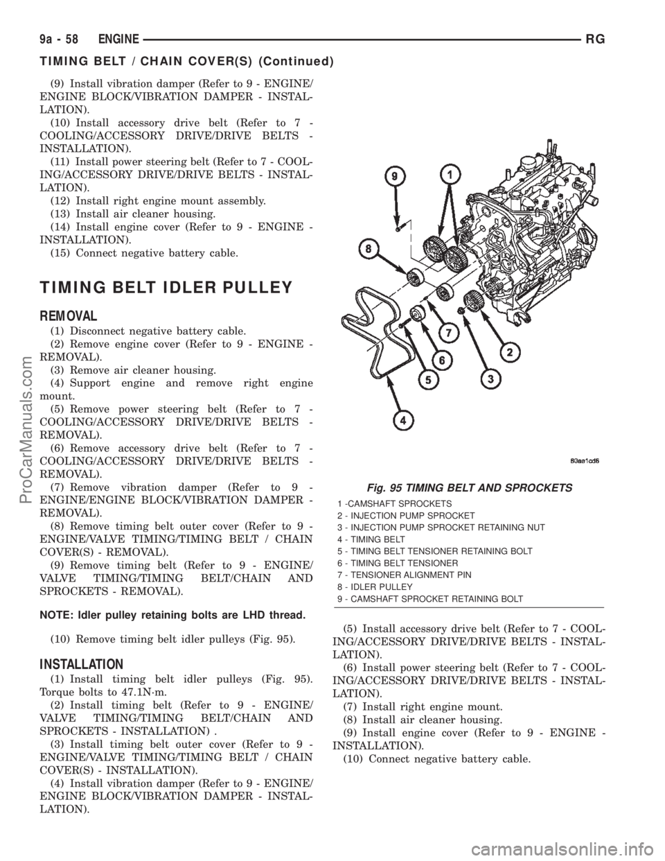
(10) Remove timing belt idler pulleys (Fig. 95).
INSTALLATION
(1) Install timing belt idler pulleys (Fig. 95).
Torque bolts to 47.1N´m.
(2) Install timing belt (Refer to 9 - ENGINE/
VALVE TIMING/TIMING BELT/CHAIN AND
SPROCKETS - INSTALLATION) .
(3) Install timing belt outer cover (Refer to 9 -
ENGINE/VALVE TIMING/TIMING BELT / CHAIN
COVER(S) - INSTALLATION).
(4) Install vibration damper (Refer to 9 - ENGINE/
ENGINE BLOCK/VIBRATION DAMPER - INSTAL-
LATION).(5) Install accessory drive belt (Refer to 7 - COOL-
ING/ACCESSORY DRIVE/DRIVE BELTS - INSTAL-
LATION).
(6) Install power steering belt (Refer to 7 - COOL-
ING/ACCESSORY DRIVE/DRIVE BELTS - INSTAL-
LATION).
(7) Install right engine mount.
(8) Install air cleaner housing.
(9) Install engine cover (Refer to 9 - ENGINE -
INSTALLATION).
(10) Connect negative battery cable.
Fig. 95 TIMING BELT AND SPROCKETS
1 -CAMSHAFT SPROCKETS
2 - INJECTION PUMP SPROCKET
3 - INJECTION PUMP SPROCKET RETAINING NUT
4 - TIMING BELT
5 - TIMING BELT TENSIONER RETAINING BOLT
6 - TIMING BELT TENSIONER
7 - TENSIONER ALIGNMENT PIN
8 - IDLER PULLEY
9 - CAMSHAFT SPROCKET RETAINING BOLT
9a - 58 ENGINERG
TIMING BELT / CHAIN COVER(S) (Continued)
ProCarManuals.com
Page 1420 of 2399
TMNG BELT/CHAIN
TENSIONER
REMOVAL
(1) Disconnect negative battery cable.
(2) Remove engine cover (Refer to 9 - ENGINE -
REMOVAL).
(3) Remove air cleaner housing.
(4) Support engine and remove right engine
mount.
(5) Remove power steering belt (Refer to 7 -
COOLING/ACCESSORY DRIVE/DRIVE BELTS -
REMOVAL).
(6) Remove accessory drive belt (Refer to 7 -
COOLING/ACCESSORY DRIVE/DRIVE BELTS -
REMOVAL).
(7) Remove vibration damper (Refer to 9 -
ENGINE/ENGINE BLOCK/VIBRATION DAMPER -
REMOVAL).
(8) Remove timing belt outer cover (Refer to 9 -
ENGINE/VALVE TIMING/TIMING BELT / CHAIN
COVER(S) - REMOVAL).
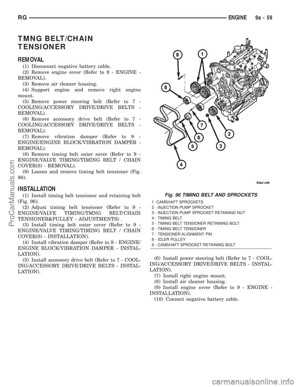
(9) Loosen and remove timing belt tensioner (Fig.
96).
INSTALLATION
(1) Install timing belt tensioner and retaining bolt
(Fig. 96).
(2) Adjust timing belt tensioner (Refer to 9 -
ENGINE/VALVE TIMING/TMNG BELT/CHAIN
TENSIONER&PULLEY - ADJUSTMENTS) .
(3) Install timing belt outer cover (Refer to 9 -
ENGINE/VALVE TIMING/TIMING BELT / CHAIN
COVER(S) - INSTALLATION).
(4) Install vibration damper (Refer to 9 - ENGINE/
ENGINE BLOCK/VIBRATION DAMPER - INSTAL-
LATION).
(5) Install accessory drive belt (Refer to 7 - COOL-
ING/ACCESSORY DRIVE/DRIVE BELTS - INSTAL-
LATION).(6) Install power steering belt (Refer to 7 - COOL-
ING/ACCESSORY DRIVE/DRIVE BELTS - INSTAL-
LATION).
(7) Install right engine mount.
(8) Install air cleaner housing.
(9) Install engine cover (Refer to 9 - ENGINE -
INSTALLATION).
(10) Connect negative battery cable.Fig. 96 TIMING BELT AND SPROCKETS
1 -CAMSHAFT SPROCKETS
2 - INJECTION PUMP SPROCKET
3 - INJECTION PUMP SPROCKET RETAINING NUT
4 - TIMING BELT
5 - TIMING BELT TENSIONER RETAINING BOLT
6 - TIMING BELT TENSIONER
7 - TENSIONER ALIGNMENT PIN
8 - IDLER PULLEY
9 - CAMSHAFT SPROCKET RETAINING BOLT
RGENGINE9a-59
ProCarManuals.com
Page 1421 of 2399
ADJUSTMENTS
ADJUSTMENT - TIMING BELT TENSIONER
(1) With timing belt outer cover removed and tim-
ing belt installed.
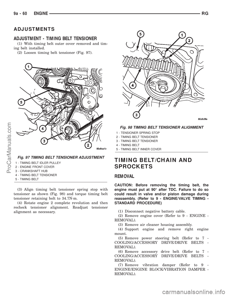
(2) Loosen timing belt tensioner (Fig. 97).
(3) Align timing belt tensioner spring stop with
tensioner as shown (Fig. 98) and torque timing belt
tensioner retaining bolt to 34.7N´m.
(4) Rotate engine 2 complete revolution and then
recheck tensioner alignment. Readjust tensioner
alignment as necessary.
TIMING BELT/CHAIN AND
SPROCKETS
REMOVAL
CAUTION: Before removing the timing belt, the
engine must put at 90É after TDC. Failure to do so
could result in valve and/or piston damage during
reassembly. (Refer to 9 - ENGINE/VALVE TIMING -
STANDARD PROCEDURE)
(1) Disconnect negative battery cable.
(2) Remove engine cover (Refer to 9 - ENGINE -
REMOVAL).
(3) Remove air cleaner housing assembly.
(4) Support engine and remove right engine
mount.
(5) Remove power steering belt (Refer to 7 -
COOLING/ACCESSORY DRIVE/DRIVE BELTS -
REMOVAL).
(6) Remove accessory drive belt (Refer to 7 -
COOLING/ACCESSORY DRIVE/DRIVE BELTS -
REMOVAL).
(7) Remove vibration damper (Refer to 9 -
ENGINE/ENGINE BLOCK/VIBRATION DAMPER -
REMOVAL).
Fig. 97 TIMING BELT TENSIONER ADJUSTMENT
1 - TIMING BELT IDLER PULLEY
2 - ENGINE FRONT COVER
3 - CRANKSHAFT HUB
4 - TIMING BELT TENSIONER
5 - TIMING BELT
Fig. 98 TIMING BELT TENSIONER ALIGNMENT
1 - TENSIONER SPRING STOP
2 - TIMING BELT TENSIONER
3 - TIMING BELT TENSIONER
4 - TIMING BELT
5 - TIMING BELT INNER COVER
9a - 60 ENGINERG
ProCarManuals.com
Page 1422 of 2399
(8) Remove timing belt outer cover (Refer to 9 -
ENGINE/VALVE TIMING/TIMING BELT / CHAIN
COVER(S) - REMOVAL).
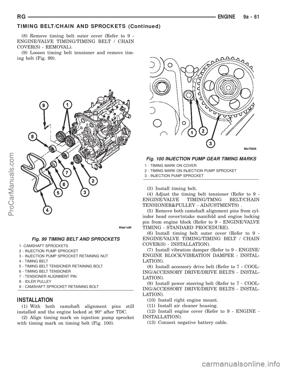
(9) Loosen timing belt tensioner and remove tim-
ing belt (Fig. 99).
INSTALLATION
(1) With both camshaft alignment pins still
installed and the engine locked at 90É after TDC.
(2) Align timing mark on injection pump sprocket
with timing mark on timing belt (Fig. 100).(3) Install timing belt.
(4) Adjust the timing belt tensioner (Refer to 9 -
ENGINE/VALVE TIMING/TMNG BELT/CHAIN
TENSIONER&PULLEY - ADJUSTMENTS) .
(5) Remove both camshaft alignment pins from cyl-
inder head cover/intake manifold and engine locking
pin from engine block (Refer to 9 - ENGINE/VALVE
TIMING - STANDARD PROCEDURE).
(6) Install timing belt outer cover (Refer to 9 -
ENGINE/VALVE TIMING/TIMING BELT / CHAIN
COVER(S) - INSTALLATION).
(7) Install vibration damper (Refer to 9 - ENGINE/
ENGINE BLOCK/VIBRATION DAMPER - INSTAL-
LATION).
(8) Install accessory drive belt (Refer to 7 - COOL-
ING/ACCESSORY DRIVE/DRIVE BELTS - INSTAL-
LATION).
(9) Install power steering belt (Refer to 7 - COOL-
ING/ACCESSORY DRIVE/DRIVE BELTS - INSTAL-
LATION).
(10) Install right engine mount.
(11) Install air cleaner housing.
(12) Install engine cover (Refer to 9 - ENGINE -
INSTALLATION).
(13) Connect negative battery cable.
Fig. 99 TIMING BELT AND SPROCKETS
1 -CAMSHAFT SPROCKETS
2 - INJECTION PUMP SPROCKET
3 - INJECTION PUMP SPROCKET RETAINING NUT
4 - TIMING BELT
5 - TIMING BELT TENSIONER RETAINING BOLT
6 - TIMING BELT TENSIONER
7 - TENSIONER ALIGNMENT PIN
8 - IDLER PULLEY
9 - CAMSHAFT SPROCKET RETAINING BOLT
Fig. 100 INJECTION PUMP GEAR TIMING MARKS
1 - TIMING MARK ON COVER
2 - TIMING MARK ON INJECTION PUMP SPROCKET
3 - INJECTION PUMP SPROCKET
RGENGINE9a-61
TIMING BELT/CHAIN AND SPROCKETS (Continued)
ProCarManuals.com
Page 1432 of 2399

CAUTION: Band clamps should never be tightened
such that the two sides of the clamps are bottomed
out against the center hourglass shaped center
block. Once this occurs, the clamp band has been
stretched and has lost its clamping force and must
be replaced.
To replace the band clamp; remove the nut and peel
back the ends of the clamp until spot weld breaks.
Clean remaining spot weld from the pipe using a
file or grinder until surface is smooth.
NOTE: Maintain proper clamp orientation when
replacing with new clamp.
(5) Tighten the band clamp to 55 N´m (40 ft. lbs.)
(Fig. 12).
(6) Connect the right side half shaft to the rear
differential module (AWD equipped only).
RESONATOR
REMOVAL
(1) (Refer to 11 - EXHAUST SYSTEM/MUFFLER -
REMOVAL)
INSTALLATION
(1) (Refer to 11 - EXHAUST SYSTEM/MUFFLER -
INSTALLATION)
Fig. 12 Band Clamp
1 - BAND CLAMP
2 - TORQUE SPECIFICATION
RSEXHAUST SYSTEM11-9
MUFFLER (Continued)
ProCarManuals.com
Page 1436 of 2399

bearing housing, routes the engine oil back to the
crankcase.
The most common turbocharger failure is bearing
failure related to repeated hot shutdowns with inad-
equate ªcool-downº periods. A sudden engine shut
down after prolonged operation will result in the
transfer of heat from the turbine section of the tur-
bocharger to the bearing housing. This causes the oil
to overheat and break down, which causes bearing
and shaft damage the next time the vehicle is
started.Letting the engine idle after extended operation
allows the turbine housing to cool to normal operat-
ing temperature. The following chart should be used
as a guide in determining the amount of engine idle
time required to sufficiently cool down the turbo-
charger before shut down, depending upon the type
of driving and the amount of cargo.
TURBOCHARGER(COOL DOWN(CHART
Driving Load Turbocharger Idle Time
(in
minuetes)
Condition Temperature Before
Shut Down
Stop & Go Empty Cool Less than 1
Stop & Go Medium Warm 1
Highway
SpeedsMedium Warm 2
City Traffic Max.
GCWRWarm 3
Highway
SpeedsMax.
GCWRWarm 4
Uphill
GradeMax.
GCWRHot 5
Fig. 3 Wastegate Operation
1 - SIGNAL LINE
2 - EXHAUST BYPASS VALVE
3 - WASTEGATE
4 - EXHAUST
5 - TURBINE
6 - EXHAUST BYPASS VALVE
7 - WASTEGATE
8 - EXHAUST
9 - TURBINE
10 - SIGNAL LINE
Fig. 4 Turbocharger Oil Supply and Drain
1 - BEARINGS
2 - OIL SUPPLY (FROM ENGINE BLOCK)
3 - OIL RETURN (TO OIL PAN)
RGEXHAUST SYSTEM AND TURBOCHARGER11a-3
TURBOCHARGER SYSTEM (Continued)
ProCarManuals.com