instrument panel CHRYSLER CARAVAN 2002 Workshop Manual
[x] Cancel search | Manufacturer: CHRYSLER, Model Year: 2002, Model line: CARAVAN, Model: CHRYSLER CARAVAN 2002Pages: 2399, PDF Size: 57.96 MB
Page 432 of 2399
ULES/POWERTRAIN CONTROL MODULE -
DESCRIPTION) section for more DTC information.
The Check Gauges Lamp (if equipped) or Battery
Lamp monitors:charging system voltage,engine
coolant temperature and engine oil pressure. If an
extreme condition is indicated, the lamp will be illu-
minated. The signal to activate the lamp is sent via
the PCI bus circuits. The lamp is located on the
instrument panel. Refer to the Instrument Cluster
section for additional information.
The PCM uses the inlet air temperature sensor to
control the charge system voltage. This temperature,
along with data from monitored line voltage, is used
by the PCM to vary the battery charging rate. The
system voltage is higher at cold temperatures and is
gradually reduced as the calculated battery tempera-
ture increases.
The ambient temperature sensor is used to control
the battery voltage based upon ambient temperature
(approximation of battery temperature). The PCM
maintains the optimal output of the generator by
monitoring battery voltage and controlling it to a
range of 13.5 - 14.7 volts based on battery tempera-
ture.
DIAGNOSIS AND TESTING - ON-BOARD
DIAGNOSTIC SYSTEM
The Powertrain Control Module (PCM) monitors
critical input and output circuits of the charging sys-
tem, making sure they are operational. A Diagnostic
Trouble Code (DTC) is assigned to each input and
output circuit monitored by the OBD system. Some
circuits are checked continuously and some are
checked only under certain conditions.
If the OBD system senses that a monitored circuit
is bad, it will put a DTC into electronic memory. The
DTC will stay in electronic memory as long as the
circuit continues to be bad. The PCM is programmed
to clear the memory after 50 engine starts if the
problem does not occur again.
DIAGNOSTIC TROUBLE CODES
A DTC description can be read using the DRBIIIt
scan tool. Refer to the appropriate Powertrain Diag-
nostic Procedures manual for information.
A DTC does not identify which component in a cir-
cuit is bad. Thus, a DTC should be treated as a
symptom, not as the cause for the problem. In some
cases, because of the design of the diagnostic test
procedure, a DTC can be the reason for another DTC
to be set. Therefore, it is important that the test pro-
cedures be followed in sequence, to understand what
caused a DTC to be set.ERASING DIAGNOSTIC TROUBLE CODES
The DRBIIItScan Tool must be used to erase a
DTC.
The following procedures may be used to diagnose
the charging system if:
²the check gauges lamp or battery lamp is illumi-
nated with the engine running
²the voltmeter (if equipped) does not register
properly
²an undercharged or overcharged battery condi-
tion occurs.
Remember that an undercharged battery is often
caused by:
²accessories being left on with the engine not
running
²a faulty or improperly adjusted switch that
allows a lamp to stay on. Refer to Ignition-Off Draw
Test (Refer to 8 - ELECTRICAL/BATTERY SYSTEM/
BATTERY - STANDARD PROCEDURE)
INSPECTION
The Powertrain Control Module (PCM) monitors
critical input and output circuits of the charging sys-
tem, making sure they are operational. A Diagnostic
Trouble Code (DTC) is assigned to each input and
output circuit monitored by the On-Board Diagnostic
(OBD) system. Some charging system circuits are
checked continuously, and some are checked only
under certain conditions.
Refer to Diagnostic Trouble Codes in; Powertrain
Control Module; Electronic Control Modules for more
DTC information. This will include a complete list of
DTC's including DTC's for the charging system.
To perform a complete test of the charging system,
refer to the appropriate Powertrain Diagnostic Proce-
dures service manual and the DRBIIItscan tool.
Perform the following inspections before attaching
the scan tool.
(1) Inspect the battery condition. Refer to the Bat-
tery section (Refer to 8 - ELECTRICAL/BATTERY
SYSTEM - DIAGNOSIS AND TESTING) for proce-
dures.
(2) Inspect condition of battery cable terminals,
battery posts, connections at engine block, starter
solenoid and relay. They should be clean and tight.
Repair as required.
(3) Inspect all fuses in both the fuseblock and
Power Distribution Center (PDC) for tightness in
receptacles. They should be properly installed and
tight. Repair or replace as required.
(4) Inspect generator mounting bolts for tightness.
Replace or tighten bolts if required. Refer to the Gen-
erator Removal/Installation section of this group for
torque specifications (Refer to 8 - ELECTRICAL/
CHARGING - SPECIFICATIONS).
RGCHARGING8Fa-21
CHARGING (Continued)
ProCarManuals.com
Page 442 of 2399

STARTING
TABLE OF CONTENTS
page page
STARTING
DESCRIPTION.........................31
OPERATION...........................31
DIAGNOSIS AND TESTING
DIAGNOSIS AND TESTING - STARTING
SYSTEM TEST.......................31
DIAGNOSIS AND TESTING - CONTROL
CIRCUIT TEST........................34
DIAGNOSIS AND TESTING - FEED CIRCUIT
RESISTANCE TEST....................36
DIAGNOSIS AND TESTING - FEED CIRCUIT
TEST...............................36
SPECIFICATIONS
STARTER ...........................37Torques.............................37
STARTER MOTOR
REMOVAL
REMOVAL - 2.4L......................38
REMOVAL - 3.3/3.8L...................39
REMOVAL - 3.5L......................39
REMOVAL - 2.5L......................40
INSTALLATION
INSTALLATION - 2.4L..................41
INSTALLATION - 3.3/3.8L................41
INSTALLATION - 3.5L..................41
INSTALLATION - 2.5L..................41
STARTING
DESCRIPTION
The starting system has (Fig. 1):
²Ignition switch
²Starter relay
²Transmission Range Sensor or Park/Neutral
Switch
²Wiring harness
²Battery
²Starter motor with an integral solenoid
²Powertrain Control Module (PCM)
OPERATION
These components form two separate circuits. A
high amperage circuit that feeds the starter motor up
to 300+ amps, and a control circuit that operates on
less than 20 amps.
The PCM controls a double start over-ride safety
that does not allow the starter to be engaged if the
engine is already running.
DIAGNOSIS AND TESTING
DIAGNOSIS AND TESTING - STARTING
SYSTEM TEST
For circuit descriptions and diagrams, refer to the
Wiring Diagrams.
WARNING: ON VEHICLES EQUIPPED WITH AIR-
BAGS, REFER TO THE PASSIVE RESTRAINT SYS-
TEMS BEFORE ATTEMPTING STEERING WHEEL,
STEERING COLUMN, OR INSTRUMENT PANEL
COMPONENT DIAGNOSIS OR SERVICE. FAILURE
TO TAKE THE PROPER PRECAUTIONS COULD
RESULT IN ACCIDENTAL AIRBAG DEPLOYMENT
AND POSSIBLE PERSONAL INJURY.
RGSTARTING8Fa-31
ProCarManuals.com
Page 455 of 2399

The electrically heated Rear Window Defogger (Fig.
1), Heated Power Side View Mirrors, and Heated
Windshield Wiper De-icer (Fig. 2)is available on
select models.
OPERATION
The Rear Window Defogger(Refer to 8 - ELECTRI-
CAL/HEATED GLASS - DESCRIPTION) system con-
sists of two vertical bus bars linked by a series of
grid lines on the inside surface of the rear window.
The electrical circuit consists of the rear defogger
switch in the HVAC control assembly and a relay
with timer switch to turn OFF the system after ten
minutes. The main feed circuit is protected by fuse
13 (40 amp) in the Power Distribution Center (PDC)
which is connected directly to the front control mod-
ule (FCM) to form an integrated unit called an Inte-
grated Power Module (IPM). The rear defogger
switch and relay also activates the heated power side
view mirrors. The rear defogger switch also activates
the heated windshield wiper de-icer which is powered
by the RUN/ACC relay in the IPM and feed thru fuse
#11 (20 amp) in the PDC. The heated mirror circuit
is protected by a non-servicable Positive Temperature
Coefficient (PTC) located inside the PDC. The heated
windshield wiper de-icer circuit is protected by fuse
11 (20 amp) in the PDC.
The Heated Windshield Wiper Deicer is also acti-
vated when the DEFROST mode is selected on the
HVAC. In the DEFROST mode the rear defogger
timout is bypassed, the heated windshield wiper de-
icer will stay ON until the another mode is selected.
For circuit information and component location refer
to appropriate section for Wiring Diagrams.
CAUTION:
Since grid lines can be damaged or scraped off
with sharp instruments, care should be taken in
cleaning the glass or removing foreign materials,
decals or stickers. Normal glass cleaning solvents
or hot water used with rags or toweling is recom-
mended.
DEFOGGER RELAY
DESCRIPTION
There is no heated windshield wiper de-icer relay.
The grid is powered directly from fuse #11 in the
PDC and is controlled directly from the HVAC con-
trol assembly.
REAR WINDOW DEFOGGER
GRID
STANDARD PROCEDURE - GRID LINE REPAIR
REAR
For Grid repair procedure for the rear window
defogger (Refer to 8 - ELECTRICAL/HEATED
GLASS/WINDSHIELD GRID - STANDARD PROCE-
DURE).
REAR WINDOW DEFOGGER
SWITCH
DESCRIPTION
The rear window defogger switch is integrated into
the HVAC control panel assembly (Fig. 3)
OPERATION
A LED indicator will illuminate when the switch is
activated. The switch energizes the HVAC control
assembly when it requests the Front Control Module
(FCM) to activate the rear window defogger relay.
The relay controls the current to flow to the grids of
the rear window defogger, heated power side view
mirrors and the heated windshield wiper de-icer. The
defogger relay will be on for approximately 10 min-
utes or until the control switch or ignition is turned
off.
Fig. 3 HVAC CONTROL PANEL
1 - TRIM BEZEL
2 - ACT SENSOR
3 - A/C REQUEST SWITCH
4 - REAR WINDOW DEFOGGER/HEATED MIRRORS SWITCH
COMBO
5 - FRONT WINDOW DEFROSTER MODE SELECTOR
8G - 2 HEATED GLASSRS
HEATED GLASS (Continued)
ProCarManuals.com
Page 460 of 2399

HEATED SEAT SYSTEM
TABLE OF CONTENTS
page page
HEATED SEAT SYSTEM
DESCRIPTION..........................7
OPERATION............................8
DIAGNOSIS AND TESTING - HEATED SEAT
SYSTEM.............................8
DRIVER HEATED SEAT SWITCH
DESCRIPTION..........................9
OPERATION............................9
DIAGNOSIS AND TESTING - DRIVER HEATED
SEAT SWITCH.........................9
REMOVAL.............................10
INSTALLATION.........................10
HEATED SEAT ELEMENT
DESCRIPTION.........................11
OPERATION...........................11
DIAGNOSIS AND TESTING - HEATED SEAT
ELEMENTS..........................11REMOVAL.............................12
INSTALLATION.........................12
HEATED SEAT SENSOR
DESCRIPTION.........................12
OPERATION...........................12
DIAGNOSIS AND TESTING - HEATED SEAT
SENSOR............................12
PASSENGER HEATED SEAT SWITCH
DESCRIPTION.........................13
OPERATION...........................13
DIAGNOSIS AND TESTING - PASSENGER
HEATED SEAT SWITCH.................13
REMOVAL.............................14
INSTALLATION.........................15
HEATED SEAT SYSTEM
DESCRIPTION
Vehicles with the heated seat option can be visu-
ally identified by the two separate heated seat
switches located in the instrument panel center
stack, just above the radio (Fig. 1). The heated seat
system allows the front seat driver and passenger to
select from two different levels of supplemental elec-
trical seat heating (HI/LO), or no seat heating to suit
their individual comfort requirements. The heated
seat system for this vehicle includes the following
major components, which are described in further
detail later in this section:
²Heated Seat Elements- Four heated seat ele-
ments are used per vehicle, two for each front seat.
One heated seat element is integral to each front
seat trim cover, one in the seat back and one in the
seat bottom (cushion). Service replacement heating
elements are available, refer to heated seat elements
later in this section for additional information.
²Heated Seat Modules- Two heated seat mod-
ules are used per vehicle. One module is mounted to
each of the seat cushion pans, located under the for-
ward edge of each front seat. Refer to heated seat
module in the electronic control modules section of
the service manual for additional information.
²Heated Seat Sensors- Two heated seat sen-
sors are used per vehicle, one for each front seat. The
heated seat sensors are integral to each of the heated
seat bottoms (cushions).
Fig. 1 HEATED SEAT SWITCH LOCATIONS
1 - HEATED SEAT SWITCHES
RSHEATED SEAT SYSTEM8G-7
ProCarManuals.com
Page 461 of 2399
²Heated Seat Switch- Two heated seat
switches are used per vehicle, one for the driver and
one for the passenger side front seats. The switches
are mounted to in the instrument panel center stack.
Refer to the description of the heated seat switch
later in this section for additional information.
Hard wired circuitry connects the heated seat sys-
tem components to each other through the electrical
system of the vehicle. These hard wired circuits are
integral to several wire harnesses, which are routed
throughout the vehicle and retained by many differ-
ent methods. These circuits may be connected to each
other, to the vehicle electrical system and to the
heated seat system components through the use of a
combination of soldered splices and splice block con-
nectors. Refer to Wiring for complete system wiring
schematics. The wiring information also includes the
proper wire and connector repair procedures, further
details on wire harness routing and retention, as well
as pin-out and location views for the various wire
harness connectors, splices and grounds.
OPERATION
The heated seat system components operate on
battery current received through a fuse in the Inte-
grated Power Module (IPM) on a fused ignition
switch output (run-acc) circuit so that the system willonly operate when the ignition switch is in the On or
Accessory positions. The heated seat system will be
turned Off automatically whenever the ignition
switch is turned to any position except On or Acces-
sory. Also, the heated seat system will not operate
when the surface temperature of the seat cushion
cover at either heated seat sensor is above the
designed temperature set points of the system. The
heated seat system has a self-diagnostic capability.
When certain failures are detected within the heated
seat system, the system will provide a visual indica-
tion of the failure by flashing the Light Emitting
Diode (LED) indicator lamps located in the heated
seat switches. See the owner's manual in the vehicle
glove box for more information on the features, use
and operation of the heated seat system.
DIAGNOSIS AND TESTING - HEATED SEAT
SYSTEM
Refer toWiring Diagramsfor complete wiring
schematics. The wiring information also includes the
proper wire and connector repair procedures, further
details on wire harness routing and retention, as well
as pin-out and location views for the various wire
harness connectors, splices and grounds.
HEATED SEAT SYSTEM DIAGNOSIS
CONDITION POSSIBLE CAUSES CORRECTION
NO HEATED SEAT SWITCH
ILLUMINATION WITH
IGNITION ON (SYSTEM ON)1. Faulty fuse 1. Check heated seat fuse in Integrated Power
Module. Replace fuse, repair short if required.
2. Faulty components 2. Refer to individual Heated Seat System
components for the proper diagnosis and testing
procedures.
3. Ground faulty 3. Check for ground at heated seat switch and
module. Repair, if required.
4. Wiring faulty 4. Check fused ignition switch output (run-acc)
circuits at switch and module. Repair, if required.
8G - 8 HEATED SEAT SYSTEMRS
HEATED SEAT SYSTEM (Continued)
ProCarManuals.com
Page 462 of 2399
DRIVER HEATED SEAT
SWITCH
DESCRIPTION
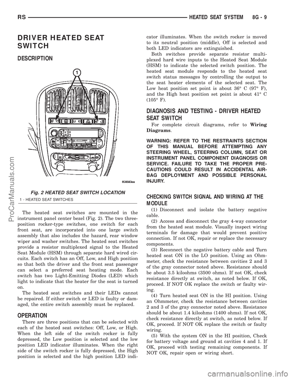
The heated seat switches are mounted in the
instrument panel center bezel (Fig. 2). The two three-
position rocker-type switches, one switch for each
front seat, are incorporated into one large switch
assembly that also includes the hazard, rear window
wiper and washer switches. The heated seat switches
provide a resistor multiplexed signal to the Heated
Seat Module (HSM) through separate hard wired cir-
cuits. Each switch has an Off, Low, and High position
so that both the driver and the front seat passenger
can select a preferred seat heating mode. Each
switch has two Light-Emitting Diodes (LED) which
light to indicate that the heater for the seat is turned
on.
The heated seat switches and their LEDs cannot
be repaired. If either switch or LED is faulty or dam-
aged, the entire switch assembly must be replaced.
OPERATION
There are three positions that can be selected with
each of the heated seat switches: Off, Low, or High.
When the left side of the switch rocker is fully
depressed, the Low position is selected and the low
position LED indicator illuminates. When the right
side of the switch rocker is fully depressed, the High
position is selected and the high position LED indi-cator illuminates. When the switch rocker is moved
to its neutral position (middle), Off is selected and
both LED indicators are extinguished.
Both switches provide separate resistor multi-
plexed hard wire inputs to the Heated Seat Module
(HSM) to indicate the selected switch position. The
heated seat module responds to the heated seat
switch status messages by controlling the output to
the seat heater elements of the selected seat. The
Low heat position set point is about 36É C (97É F),
and the High heat position set point is about 41É C
(105É F).
DIAGNOSIS AND TESTING - DRIVER HEATED
SEAT SWITCH
For complete circuit diagrams, refer toWiring
Diagrams.
WARNING: REFER TO THE RESTRAINTS SECTION
OF THIS MANUAL BEFORE ATTEMPTING ANY
STEERING WHEEL, STEERING COLUMN, SEAT OR
INSTRUMENT PANEL COMPONENT DIAGNOSIS OR
SERVICE. FAILURE TO TAKE THE PROPER PRE-
CAUTIONS COULD RESULT IN ACCIDENTAL AIR-
BAG DEPLOYMENT AND POSSIBLE PERSONAL
INJURY.
CHECKING SWITCH SIGNAL AND WIRING AT THE
MODULE
(1) Disconnect and isolate the battery negative
cable.
(2) Access and disconnect the gray 4-way connector
from the heated seat module. Visually inspect wiring
terminals for damage that would prevent positive
connection. If not OK, repair or replace the necessary
components.
(3) Reconnect the negative battery cable and Turn
heated seat ON in the LO position. Using an Ohm-
meter, check the resistance between cavities 2 and 3
of the gray connector noted above. Resistance should
be about 3.5 kiloohms (3500 ohms). If not OK, check
resistance directly at switch, as noted below. If OK,
proceed. If NOT OK replace the switch or faulty wir-
ing.
(4) Turn heated seat ON in the HI position. Using
an Ohmmeter, check the resistance between cavities
2 and 3 of the gray connector noted above. Resistance
should be about 1.4 kiloohms (1400 ohms). If not OK,
check resistance directly at switch, as noted below. If
OK, proceed. If NOT OK replace the switch or faulty
wiring.
(5) With the system ON in the HI position, Check
for battery voltage and ground at cavities 4 and 1. If
OK, proceed with testing remaining components. If
NOT OK, repair open or wiring short.
Fig. 2 HEATED SEAT SWITCH LOCATION
1 - HEATED SEAT SWITCHES
RSHEATED SEAT SYSTEM8G-9
ProCarManuals.com
Page 463 of 2399
CHECKING SWITCH ONLY
(1) Disconnect and isolate the battery negative
cable. Remove the center bezel from the instrument
panel (Refer to 23 - BODY/INSTRUMENT PANEL/
INSTRUMENT PANEL CENTER BEZEL - REMOV-
AL). Check for continuity between the ground circuit
cavity (#10) of the instrument panel switch bank
electrical connector and a good ground. There should
be continuity. If OK, go to Step 2. If not OK, repair
the open ground circuit to ground as required.
(2) Reconnect the battery negative cable. Turn the
ignition switch to the On position. Check for battery
voltage at the fused ignition switch output (run) cir-
cuit cavity of the instrument panel switch bank con-
nector (#4). If OK, turn the ignition switch to the Off
position, and go to Step 3. If not OK, repair the open
fused ignition switch output (run) circuit as required.
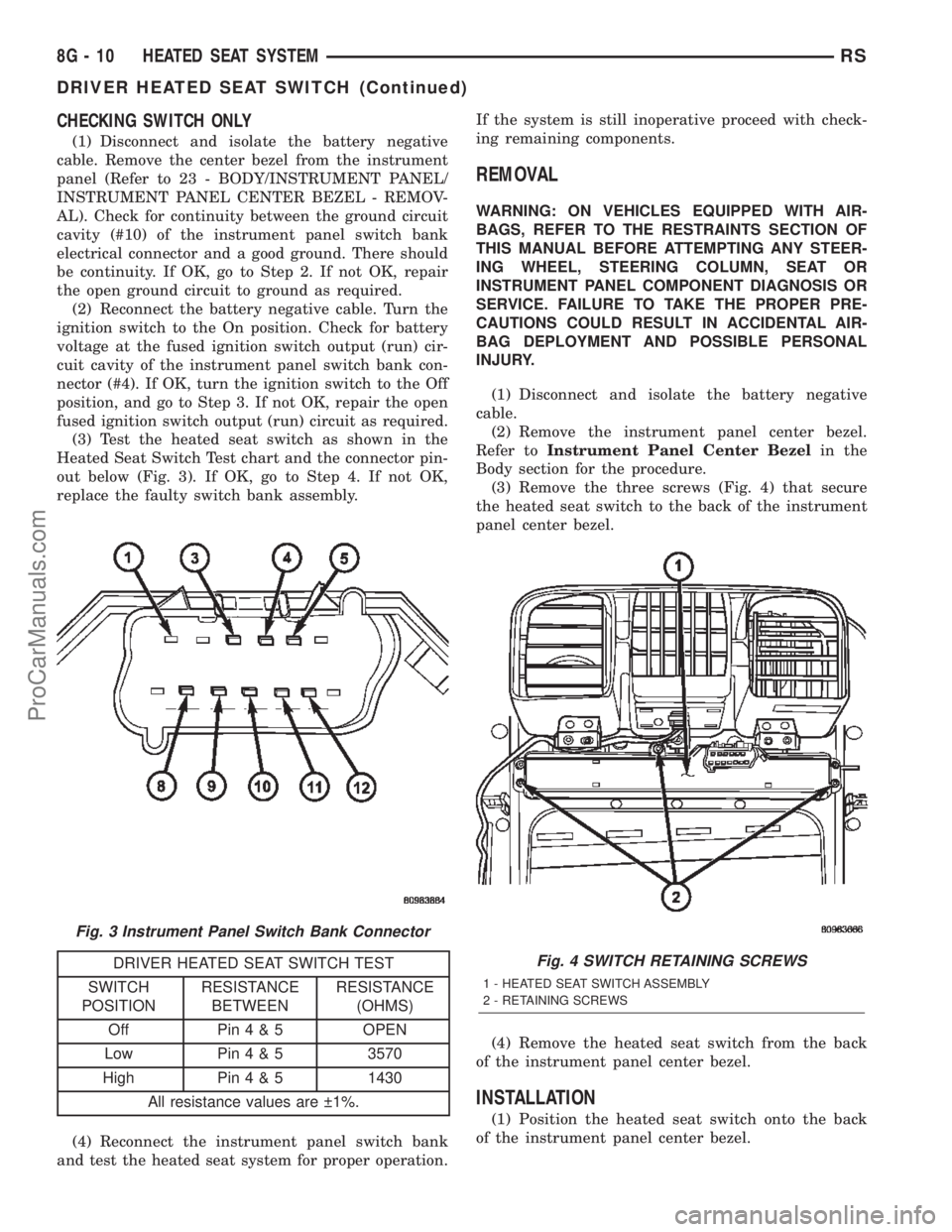
(3) Test the heated seat switch as shown in the
Heated Seat Switch Test chart and the connector pin-
out below (Fig. 3). If OK, go to Step 4. If not OK,
replace the faulty switch bank assembly.
DRIVER HEATED SEAT SWITCH TEST
SWITCH
POSITIONRESISTANCE
BETWEENRESISTANCE
(OHMS)
Off Pin4&5OPEN
Low Pin4&53570
High Pin4&51430
All resistance values are 1%.
(4) Reconnect the instrument panel switch bank
and test the heated seat system for proper operation.If the system is still inoperative proceed with check-
ing remaining components.
REMOVAL
WARNING: ON VEHICLES EQUIPPED WITH AIR-
BAGS, REFER TO THE RESTRAINTS SECTION OF
THIS MANUAL BEFORE ATTEMPTING ANY STEER-
ING WHEEL, STEERING COLUMN, SEAT OR
INSTRUMENT PANEL COMPONENT DIAGNOSIS OR
SERVICE. FAILURE TO TAKE THE PROPER PRE-
CAUTIONS COULD RESULT IN ACCIDENTAL AIR-
BAG DEPLOYMENT AND POSSIBLE PERSONAL
INJURY.
(1) Disconnect and isolate the battery negative
cable.
(2) Remove the instrument panel center bezel.
Refer toInstrument Panel Center Bezelin the
Body section for the procedure.
(3) Remove the three screws (Fig. 4) that secure
the heated seat switch to the back of the instrument
panel center bezel.
(4) Remove the heated seat switch from the back
of the instrument panel center bezel.
INSTALLATION
(1) Position the heated seat switch onto the back
of the instrument panel center bezel.
Fig. 3 Instrument Panel Switch Bank Connector
Fig. 4 SWITCH RETAINING SCREWS
1 - HEATED SEAT SWITCH ASSEMBLY
2 - RETAINING SCREWS
8G - 10 HEATED SEAT SYSTEMRS
DRIVER HEATED SEAT SWITCH (Continued)
ProCarManuals.com
Page 464 of 2399
(2) Install and tighten the three screws that secure
the heated seat switch to the back of the instrument
panel center bezel. Tighten the screws to 1.5 N´m (13
in. lbs.) (Fig. 4).
(3) Install the center bezel onto the instrument
panel. Refer toInstrument Panel Center Bezelin
the Body section for the procedure.
(4) Reconnect the battery negative cable.
HEATED SEAT ELEMENT
DESCRIPTION
The heated seat system includes two seat heating ele-
ments in each front seat, one for the seat cushion and
the other for the seat back. The two elements for each
seat that are connected in series with the Heated Seat
Module (HSM). The temperature sensor is a Negative
Temperature Coefficient (NTC) thermistor. One temper-
ature sensor is used for each seat, and it is located on
the seat cushion heating element for all models.
The seat heating elements are sewn into the seat
cushion cover trim and seat back cover trim units.
The heated seat elements and the temperature sen-
sor cannot be adjusted or repaired and, if faulty or
damaged, the seat element assembly must be
replaced. Refer to the procedure in this section.
OPERATION
The heated seat elements resist the flow of electrical
current. When battery current is passed through the
elements, the energy lost by the resistance of the ele-
ments to the current flow is released in the form of
heat. The temperature sensor is a NTC thermistor.
When the temperature of the seat cushion cover rises,
the resistance of the sensor decreases. The heated seat
module supplies a five-volt current to one side of each
sensor, and monitors the voltage drop through the
sensor on a return circuit. The heated seat module
uses this temperature sensor input to monitor the
temperature of the seat, and regulates the current
flow to the seat heating elements accordingly.
DIAGNOSIS AND TESTING - HEATED SEAT
ELEMENTS
The wire harness connectors for the seat cushion and
seat back heating elements are located under the seat,
at the heated seat module. For circuit descriptions and
diagrams, refer to section 8W, Wiring Diagrams.
In order to access and test the heated seat ele-
ments it will be necessary to remove the appropriate
front seat retaining bolts and lay the seat rearward,
up against one of the rear seats. It is not necessary
to disconnect the seat electrical connectors, just use
care not to damage the attached wire harnesses
while testing.NOTE: WHEN CHECKING HEATED SEAT ELE-
MENTS FOR CONTINUITY, BE CERTAIN TO MOVE
THE HEATING ELEMENT BEING CHECKED. MOV-
ING THE ELEMENT, SUCH AS SITTING IN THE SEAT
WILL ELIMINATE THE POSSIBILITY OF AN INTER-
MITTENT OPEN IN THE ELEMENT WHICH WOULD
ONLY BE EVIDENT IF THE ELEMENT WAS MOVED
IN A CERTAIN DIRECTION. FAILURE TO CHECK
THE ELEMENT IN VARIOUS POSITIONS COULD
RESULT IN AN INCOMPLETE TEST.
SEAT CUSHION ELEMENT
(1) From under the vehicle, remove the appropri-
ate seats four retaining nuts.
(2) From inside the vehicle, pull the seat up, off
the mounting studs and lay it back, up against one of
the rear seats.
(3) Locate the heated seat module, attached to the
bottom of the seat cushion pan. Remove the heated
seat module from the seat cushion pan. Do not dis-
connect the electrical connectors at this time.
(4) Locate the green 4-way electrical connector,
connected to the heated seat module. Disconnect the
green 4-way connector from the heated seat module.
(5) Check for continuity between the two outboard
circuit cavities of the wire harness connector (Pins
1&4). There should be continuity. If OK, refer to
Heated Seat Module Diagnosis and Testing in the
Electronic Control Modules section of the service
manual for complete system testing procedures. If
not OK, install a replacement heated seat cushion
element. Refer to the procedure in this section.
SEAT BACK ELEMENT
(1) From under the vehicle, remove the appropri-
ate seats four retaining nuts.
(2) From inside the vehicle, pull the seat up and
off the mounting studs and lay it back, up against
one of the rear seats.
(3) Locate the heated seat module, attached to the
bottom of the seat cushion pan. Remove the heated
seat module from the seat cushion pan. Do not dis-
connect the electrical connectors at this time.
(4) Locate the gray 2-way electrical connector, con-
nected to the heated seat module. Disconnect the
2-way connector from the heated seat module.
(5) Check for continuity between the two circuit
cavities of the 2-way wire harness connector. There
should be continuity. If OK, refer to Heated Seat
Module Diagnosis and Testing in the Electronic Con-
trol Modules section of the service manual for com-
plete system testing procedures. If not OK, install a
replacement heated seat back element. Refer to the
procedure in this section.
RSHEATED SEAT SYSTEM8G-11
DRIVER HEATED SEAT SWITCH (Continued)
ProCarManuals.com
Page 466 of 2399
PASSENGER HEATED SEAT
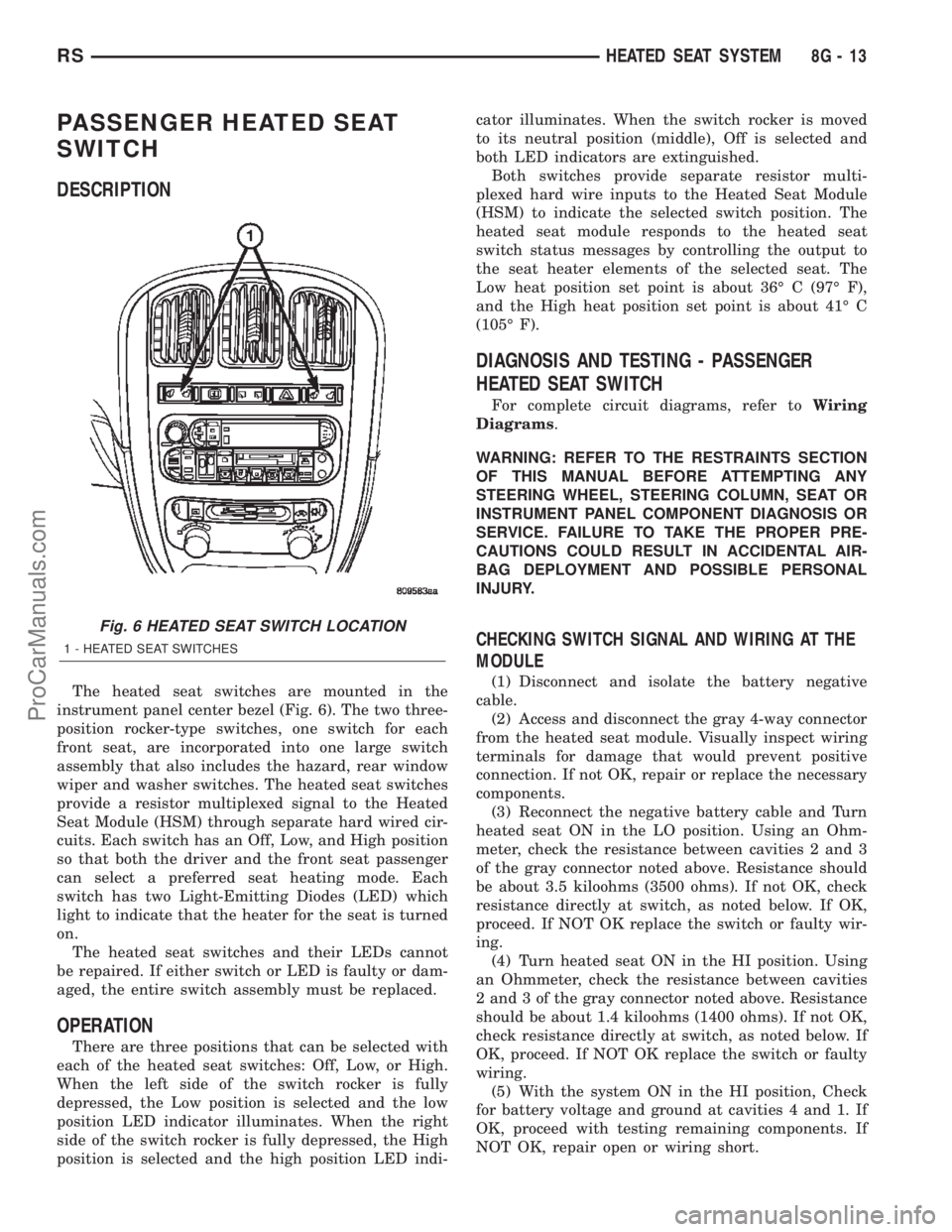
SWITCH
DESCRIPTION
The heated seat switches are mounted in the
instrument panel center bezel (Fig. 6). The two three-
position rocker-type switches, one switch for each
front seat, are incorporated into one large switch
assembly that also includes the hazard, rear window
wiper and washer switches. The heated seat switches
provide a resistor multiplexed signal to the Heated
Seat Module (HSM) through separate hard wired cir-
cuits. Each switch has an Off, Low, and High position
so that both the driver and the front seat passenger
can select a preferred seat heating mode. Each
switch has two Light-Emitting Diodes (LED) which
light to indicate that the heater for the seat is turned
on.
The heated seat switches and their LEDs cannot
be repaired. If either switch or LED is faulty or dam-
aged, the entire switch assembly must be replaced.
OPERATION
There are three positions that can be selected with
each of the heated seat switches: Off, Low, or High.
When the left side of the switch rocker is fully
depressed, the Low position is selected and the low
position LED indicator illuminates. When the right
side of the switch rocker is fully depressed, the High
position is selected and the high position LED indi-cator illuminates. When the switch rocker is moved
to its neutral position (middle), Off is selected and
both LED indicators are extinguished.
Both switches provide separate resistor multi-
plexed hard wire inputs to the Heated Seat Module
(HSM) to indicate the selected switch position. The
heated seat module responds to the heated seat
switch status messages by controlling the output to
the seat heater elements of the selected seat. The
Low heat position set point is about 36É C (97É F),
and the High heat position set point is about 41É C
(105É F).
DIAGNOSIS AND TESTING - PASSENGER
HEATED SEAT SWITCH
For complete circuit diagrams, refer toWiring
Diagrams.
WARNING: REFER TO THE RESTRAINTS SECTION
OF THIS MANUAL BEFORE ATTEMPTING ANY
STEERING WHEEL, STEERING COLUMN, SEAT OR
INSTRUMENT PANEL COMPONENT DIAGNOSIS OR
SERVICE. FAILURE TO TAKE THE PROPER PRE-
CAUTIONS COULD RESULT IN ACCIDENTAL AIR-
BAG DEPLOYMENT AND POSSIBLE PERSONAL
INJURY.
CHECKING SWITCH SIGNAL AND WIRING AT THE
MODULE
(1) Disconnect and isolate the battery negative
cable.
(2) Access and disconnect the gray 4-way connector
from the heated seat module. Visually inspect wiring
terminals for damage that would prevent positive
connection. If not OK, repair or replace the necessary
components.
(3) Reconnect the negative battery cable and Turn
heated seat ON in the LO position. Using an Ohm-
meter, check the resistance between cavities 2 and 3
of the gray connector noted above. Resistance should
be about 3.5 kiloohms (3500 ohms). If not OK, check
resistance directly at switch, as noted below. If OK,
proceed. If NOT OK replace the switch or faulty wir-
ing.
(4) Turn heated seat ON in the HI position. Using
an Ohmmeter, check the resistance between cavities
2 and 3 of the gray connector noted above. Resistance
should be about 1.4 kiloohms (1400 ohms). If not OK,
check resistance directly at switch, as noted below. If
OK, proceed. If NOT OK replace the switch or faulty
wiring.
(5) With the system ON in the HI position, Check
for battery voltage and ground at cavities 4 and 1. If
OK, proceed with testing remaining components. If
NOT OK, repair open or wiring short.
Fig. 6 HEATED SEAT SWITCH LOCATION
1 - HEATED SEAT SWITCHES
RSHEATED SEAT SYSTEM8G-13
ProCarManuals.com
Page 467 of 2399
CHECKING SWITCH ONLY
(1) Disconnect and isolate the battery negative
cable. Remove the center bezel from the instrument
panel (Refer to 23 - BODY/INSTRUMENT PANEL/
INSTRUMENT PANEL CENTER BEZEL - REMOV-
AL). Check for continuity between the ground circuit
cavity (#10) of the instrument panel switch bank
electrical connector and a good ground. There should
be continuity. If OK, go to Step 2. If not OK, repair
the open ground circuit to ground as required.
(2) Reconnect the battery negative cable. Turn the
ignition switch to the On position. Check for battery
voltage at the fused ignition switch output (run) cir-
cuit cavity of the instrument panel switch bank con-
nector (#4). If OK, turn the ignition switch to the Off
position, and go to Step 3. If not OK, repair the open
fused ignition switch output (run) circuit as required.
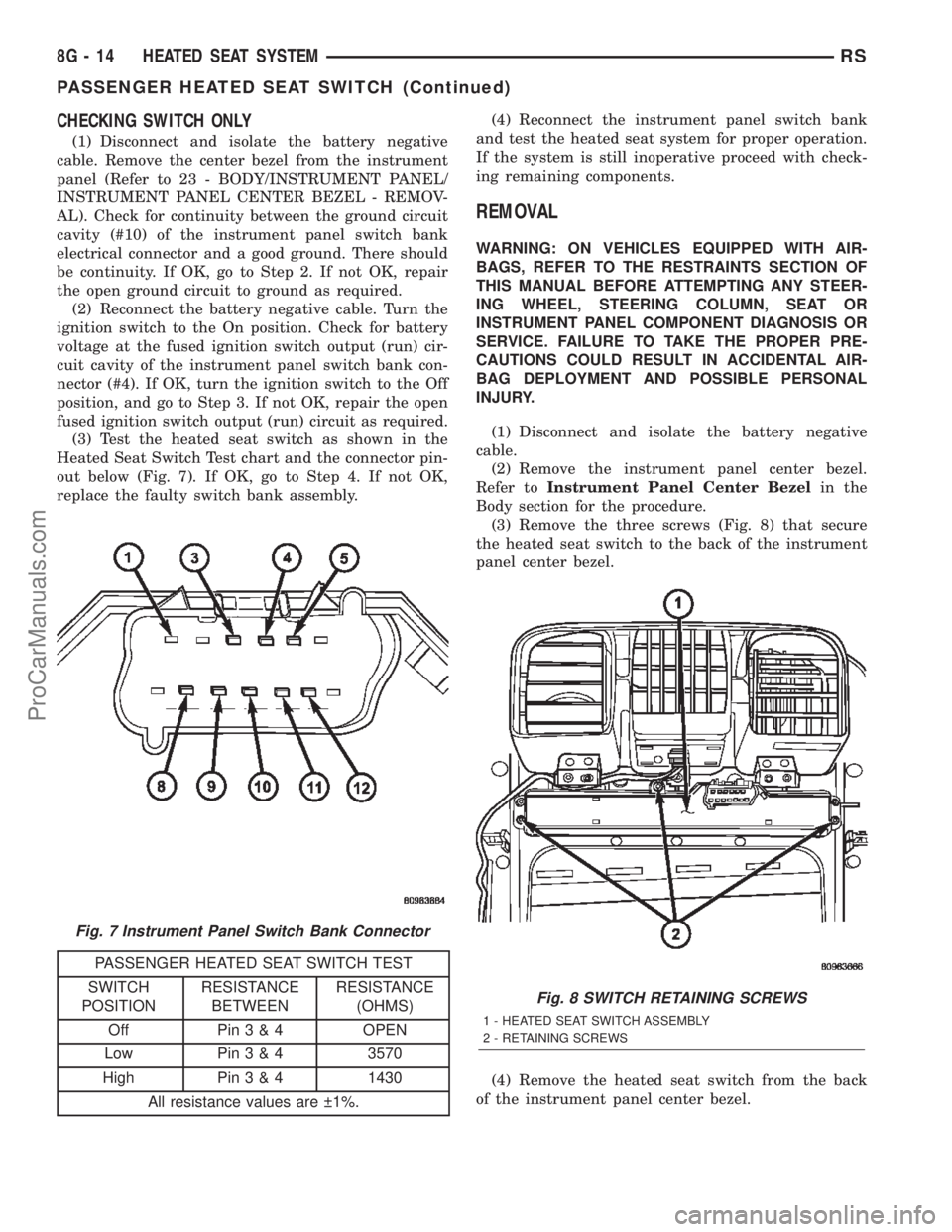
(3) Test the heated seat switch as shown in the
Heated Seat Switch Test chart and the connector pin-
out below (Fig. 7). If OK, go to Step 4. If not OK,
replace the faulty switch bank assembly.
PASSENGER HEATED SEAT SWITCH TEST
SWITCH
POSITIONRESISTANCE
BETWEENRESISTANCE
(OHMS)
Off Pin3&4OPEN
Low Pin3&43570
High Pin3&41430
All resistance values are 1%.(4) Reconnect the instrument panel switch bank
and test the heated seat system for proper operation.
If the system is still inoperative proceed with check-
ing remaining components.
REMOVAL
WARNING: ON VEHICLES EQUIPPED WITH AIR-
BAGS, REFER TO THE RESTRAINTS SECTION OF
THIS MANUAL BEFORE ATTEMPTING ANY STEER-
ING WHEEL, STEERING COLUMN, SEAT OR
INSTRUMENT PANEL COMPONENT DIAGNOSIS OR
SERVICE. FAILURE TO TAKE THE PROPER PRE-
CAUTIONS COULD RESULT IN ACCIDENTAL AIR-
BAG DEPLOYMENT AND POSSIBLE PERSONAL
INJURY.
(1) Disconnect and isolate the battery negative
cable.
(2) Remove the instrument panel center bezel.
Refer toInstrument Panel Center Bezelin the
Body section for the procedure.
(3) Remove the three screws (Fig. 8) that secure
the heated seat switch to the back of the instrument
panel center bezel.
(4) Remove the heated seat switch from the back
of the instrument panel center bezel.
Fig. 7 Instrument Panel Switch Bank Connector
Fig. 8 SWITCH RETAINING SCREWS
1 - HEATED SEAT SWITCH ASSEMBLY
2 - RETAINING SCREWS
8G - 14 HEATED SEAT SYSTEMRS
PASSENGER HEATED SEAT SWITCH (Continued)
ProCarManuals.com