instrument panel CHRYSLER CARAVAN 2002 Service Manual
[x] Cancel search | Manufacturer: CHRYSLER, Model Year: 2002, Model line: CARAVAN, Model: CHRYSLER CARAVAN 2002Pages: 2399, PDF Size: 57.96 MB
Page 6 of 2399
FASTENER USAGE
DESCRIPTION
DESCRIPTION - FASTENER USAGE
WARNING: USE OF AN INCORRECT FASTENER
MAY RESULT IN COMPONENT DAMAGE OR PER-
SONAL INJURY.
Fasteners and torque specifications references in
this Service Manual are identified in metric and SAE
format.
During any maintenance or repair procedures, it is
important to salvage all fasteners (nuts, bolts, etc.)
for reassembly. If the fastener is not salvageable, a
fastener of equivalent specification must be used.
DESCRIPTION - THREADED HOLE REPAIR
Most stripped threaded holes can be repaired using
a Helicoilt. Follow the vehicle or Helicoiltrecommen-
dations for application and repair procedures.
INTERNATIONAL SYMBOLS
DESCRIPTION
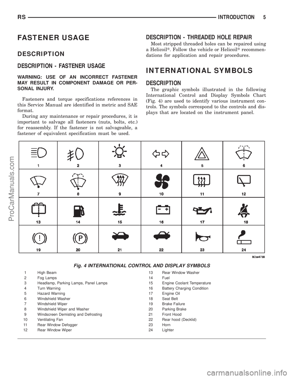
The graphic symbols illustrated in the following
International Control and Display Symbols Chart
(Fig. 4) are used to identify various instrument con-
trols. The symbols correspond to the controls and dis-
plays that are located on the instrument panel.
Fig. 4 INTERNATIONAL CONTROL AND DISPLAY SYMBOLS
1 High Beam 13 Rear Window Washer
2 Fog Lamps 14 Fuel
3 Headlamp, Parking Lamps, Panel Lamps 15 Engine Coolant Temperature
4 Turn Warning 16 Battery Charging Condition
5 Hazard Warning 17 Engine Oil
6 Windshield Washer 18 Seat Belt
7 Windshield Wiper 19 Brake Failure
8 Windshield Wiper and Washer 20 Parking Brake
9 Windscreen Demisting and Defrosting 21 Front Hood
10 Ventilating Fan 22 Rear hood (Decklid)
11 Rear Window Defogger 23 Horn
12 Rear Window Wiper 24 Lighter
RSINTRODUCTION5
ProCarManuals.com
Page 10 of 2399

VEHICLE IDENTIFICATION
NUMBER
DESCRIPTION
The Vehicle Identification Number (VIN) can be
viewed through the windshield at the upper left cor-
ner of the instrument panel, near the left windshield
pillar (Fig. 7). The VIN consists of 17 characters in a
combination of letters and numbers that provide spe-
cific information about the vehicle. Refer to VIN
Code Breakdown Chart for decoding information.
To protect the consumer from theft and possible
fraud the manufacturer is required to include a
Check Digit at the ninth position of the vehicle iden-
tification number. The check digit is used by the
manufacturer and government agencies to verify the
authenticity of the vehicle and official documenta-
tion. The formula to use the check digit is not
released to the general public.
VIN CODE BREAKDOWN CHART
POSITION INTERPRETATION CODE = DESCRIPTION
1 Country of Origin 1 = Built in the United States by DaimlerChrysler
2 = Built in Canada by DaimlerChrysler Canada Inc.
2 Make B = Dodge
C = Chrysler
3 Vehicle Type 4 = Multipurpose Pass. Vehicle Less Side Air Bags
8 = Multipurpose Pass. Vehicle With Side Air Bags
4 Gross Vehicle Weight Rating G = 2268 - 2721 kg. (5001 - 6000 lbs.)
5 Car Line P = Chrysler, Town & Country - FWD
P = Dodge, Caravan/Grand Caravan - FWD
T = Chrysler, Town & Country - AWD
T = Dodge, Grand Caravan - AWD
J = Chrysler, Voyager/Grand Voyager - FWD
Y = Voyager/Grand Voyager - FWD Left Hand Drive
C = Voyager/Grand Voyager - AWD Left Hand Drive
H = Voyager/Grand Voyager - FWD Right Hand Drive
K = Voyager/Grand Voyager - AWD Left Hand Drive
Fig. 7 VEHICLE IDENTIFICATION NUMBER (VIN)
1 - DEFROSTER OUTLET
2 - VEHICLE IDENTIFICATION NUMBER
3 - HEATED WINDSHIELD GRID
RSINTRODUCTION9
ProCarManuals.com
Page 140 of 2399
ADJUSTABLE PEDAL SWITCH
DESCRIPTION
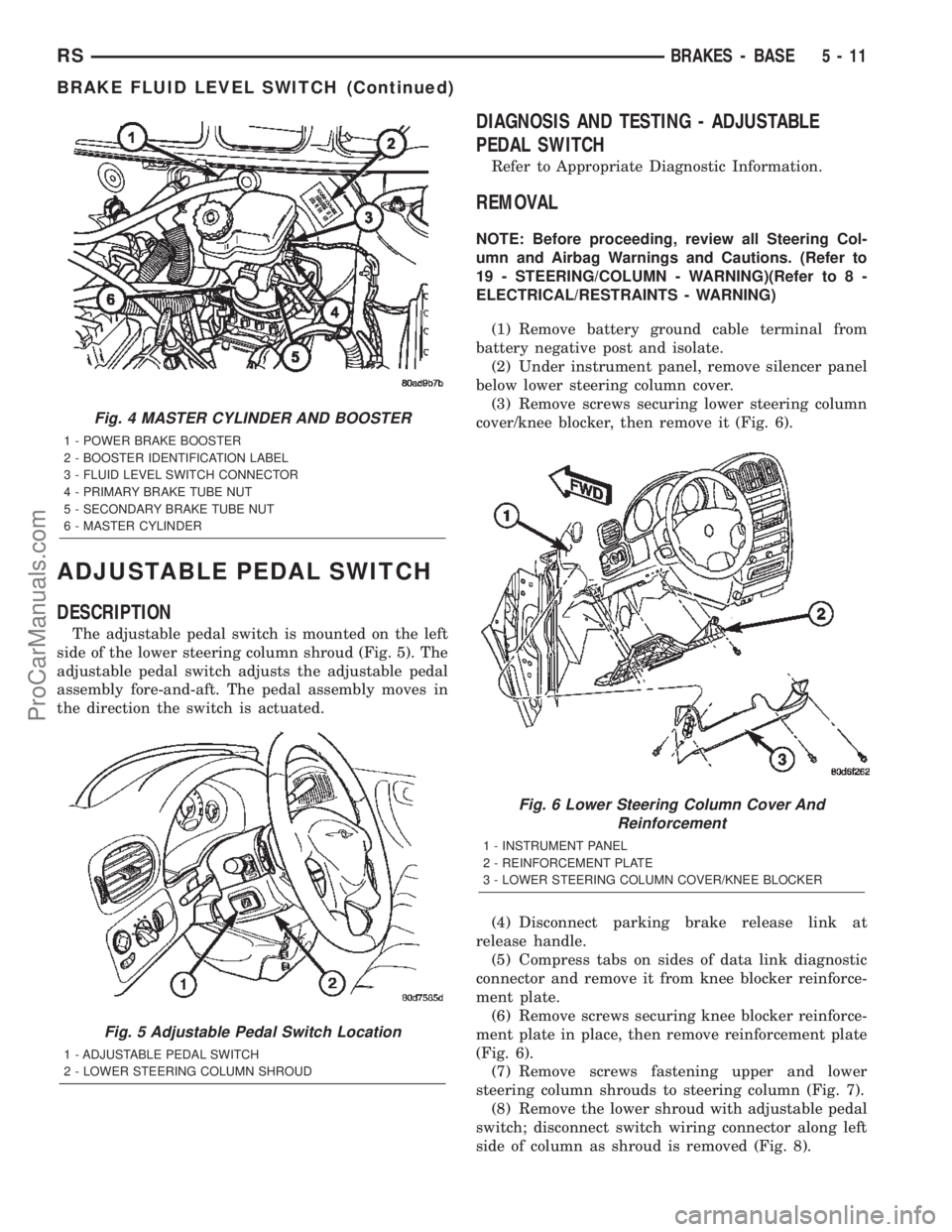
The adjustable pedal switch is mounted on the left
side of the lower steering column shroud (Fig. 5). The
adjustable pedal switch adjusts the adjustable pedal
assembly fore-and-aft. The pedal assembly moves in
the direction the switch is actuated.
DIAGNOSIS AND TESTING - ADJUSTABLE
PEDAL SWITCH
Refer to Appropriate Diagnostic Information.
REMOVAL
NOTE: Before proceeding, review all Steering Col-
umn and Airbag Warnings and Cautions. (Refer to
19 - STEERING/COLUMN - WARNING)(Refer to 8 -
ELECTRICAL/RESTRAINTS - WARNING)
(1) Remove battery ground cable terminal from
battery negative post and isolate.
(2) Under instrument panel, remove silencer panel
below lower steering column cover.
(3) Remove screws securing lower steering column
cover/knee blocker, then remove it (Fig. 6).
(4) Disconnect parking brake release link at
release handle.
(5) Compress tabs on sides of data link diagnostic
connector and remove it from knee blocker reinforce-
ment plate.
(6) Remove screws securing knee blocker reinforce-
ment plate in place, then remove reinforcement plate
(Fig. 6).
(7) Remove screws fastening upper and lower
steering column shrouds to steering column (Fig. 7).
(8) Remove the lower shroud with adjustable pedal
switch; disconnect switch wiring connector along left
side of column as shroud is removed (Fig. 8).
Fig. 4 MASTER CYLINDER AND BOOSTER
1 - POWER BRAKE BOOSTER
2 - BOOSTER IDENTIFICATION LABEL
3 - FLUID LEVEL SWITCH CONNECTOR
4 - PRIMARY BRAKE TUBE NUT
5 - SECONDARY BRAKE TUBE NUT
6 - MASTER CYLINDER
Fig. 5 Adjustable Pedal Switch Location
1 - ADJUSTABLE PEDAL SWITCH
2 - LOWER STEERING COLUMN SHROUD
Fig. 6 Lower Steering Column Cover And
Reinforcement
1 - INSTRUMENT PANEL
2 - REINFORCEMENT PLATE
3 - LOWER STEERING COLUMN COVER/KNEE BLOCKER
RSBRAKES - BASE5-11
BRAKE FLUID LEVEL SWITCH (Continued)
ProCarManuals.com
Page 142 of 2399
DIAGNOSIS AND TESTING - PEDAL POSITION
SENSOR
Refer to Appropriate Diagnostic Information.
REMOVAL
(1) Remove battery ground cable terminal from
battery negative post and isolate.
(2) Under instrument panel, remove silencer panel
below lower steering column cover.
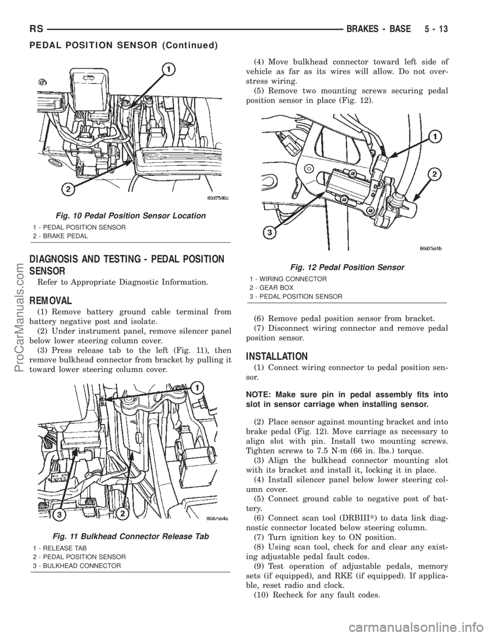
(3) Press release tab to the left (Fig. 11), then
remove bulkhead connector from bracket by pulling it
toward lower steering column cover.(4) Move bulkhead connector toward left side of
vehicle as far as its wires will allow. Do not over-
stress wiring.
(5) Remove two mounting screws securing pedal
position sensor in place (Fig. 12).
(6) Remove pedal position sensor from bracket.
(7) Disconnect wiring connector and remove pedal
position sensor.
INSTALLATION
(1) Connect wiring connector to pedal position sen-
sor.
NOTE: Make sure pin in pedal assembly fits into
slot in sensor carriage when installing sensor.
(2) Place sensor against mounting bracket and into
brake pedal (Fig. 12). Move carriage as necessary to
align slot with pin. Install two mounting screws.
Tighten screws to 7.5 N´m (66 in. lbs.) torque.
(3) Align the bulkhead connector mounting slot
with its bracket and install it, locking it in place.
(4) Install silencer panel below lower steering col-
umn cover.
(5) Connect ground cable to negative post of bat-
tery.
(6) Connect scan tool (DRBIIIt) to data link diag-
nostic connector located below steering column.
(7) Turn ignition key to ON position.
(8) Using scan tool, check for and clear any exist-
ing adjustable pedal fault codes.
(9) Test operation of adjustable pedals, memory
sets (if equipped), and RKE (if equipped). If applica-
ble, reset radio and clock.
(10) Recheck for any fault codes.
Fig. 10 Pedal Position Sensor Location
1 - PEDAL POSITION SENSOR
2 - BRAKE PEDAL
Fig. 11 Bulkhead Connector Release Tab
1 - RELEASE TAB
2 - PEDAL POSITION SENSOR
3 - BULKHEAD CONNECTOR
Fig. 12 Pedal Position Sensor
1 - WIRING CONNECTOR
2 - GEAR BOX
3 - PEDAL POSITION SENSOR
RSBRAKES - BASE5-13
PEDAL POSITION SENSOR (Continued)
ProCarManuals.com
Page 172 of 2399
ing pedal adjustment, the APM will monitor pedal
position sensor voltage. If the APM does not detect
expected voltage change within 3 seconds, it will cut
power to the adjustable pedal motor.
An optional memory feature is available. This
allows storing of one or two preferred pedal positions
in the APS. A preferred position can be stored and
recalled using the door-mounted switches. A stored
pedal position can be recalled (but not stored) using
the Remote Keyless Entry (RKE) if equipped with
the memory feature.
DIAGNOSIS AND TESTING - ADJUSTABLE
PEDAL SYSTEM
Refer to Appropriate Diagnostic Information.
REMOVAL
NOTE: Before proceeding, review all Steering Col-
umn and Airbag Warnings and Cautions. (Refer to
19 - STEERING/COLUMN - WARNING)(Refer to 8 -
ELECTRICAL/RESTRAINTS - WARNING)
(1) Remove battery ground cable terminal from
battery negative post and isolate.
(2) Under instrument panel, remove silencer panel
below lower steering column cover.
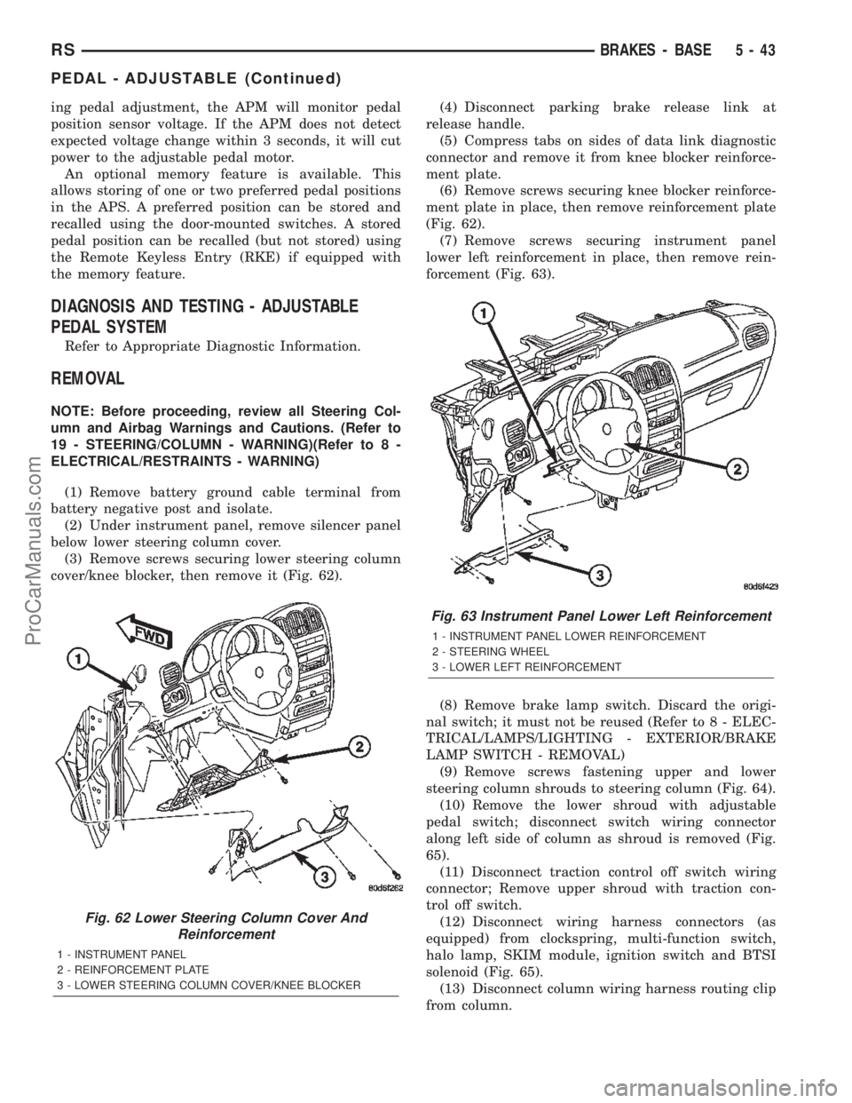
(3) Remove screws securing lower steering column
cover/knee blocker, then remove it (Fig. 62).(4) Disconnect parking brake release link at
release handle.
(5) Compress tabs on sides of data link diagnostic
connector and remove it from knee blocker reinforce-
ment plate.
(6) Remove screws securing knee blocker reinforce-
ment plate in place, then remove reinforcement plate
(Fig. 62).
(7) Remove screws securing instrument panel
lower left reinforcement in place, then remove rein-
forcement (Fig. 63).
(8) Remove brake lamp switch. Discard the origi-
nal switch; it must not be reused (Refer to 8 - ELEC-
TRICAL/LAMPS/LIGHTING - EXTERIOR/BRAKE
LAMP SWITCH - REMOVAL)
(9) Remove screws fastening upper and lower
steering column shrouds to steering column (Fig. 64).
(10) Remove the lower shroud with adjustable
pedal switch; disconnect switch wiring connector
along left side of column as shroud is removed (Fig.
65).
(11) Disconnect traction control off switch wiring
connector; Remove upper shroud with traction con-
trol off switch.
(12) Disconnect wiring harness connectors (as
equipped) from clockspring, multi-function switch,
halo lamp, SKIM module, ignition switch and BTSI
solenoid (Fig. 65).
(13) Disconnect column wiring harness routing clip
from column.
Fig. 62 Lower Steering Column Cover And
Reinforcement
1 - INSTRUMENT PANEL
2 - REINFORCEMENT PLATE
3 - LOWER STEERING COLUMN COVER/KNEE BLOCKER
Fig. 63 Instrument Panel Lower Left Reinforcement
1 - INSTRUMENT PANEL LOWER REINFORCEMENT
2 - STEERING WHEEL
3 - LOWER LEFT REINFORCEMENT
RSBRAKES - BASE5-43
PEDAL - ADJUSTABLE (Continued)
ProCarManuals.com
Page 174 of 2399

(19) Loosen two lower column mounting nuts.
(20) Remove two upper column mounting nuts.
(21) Remove the steering column.
(22) Remove dash seal silencer shell over steering
column intermediate shaft (Fig. 68).
(23) Remove two nuts securing brake lamp switch
bracket to pedal assembly (Fig. 69). Remove bracket.(24) Disconnect pedal wiring harness connector
(Fig. 69).
(25) Remove pedal wiring harness from clips along
pedal bracket.
(26) Position a small screwdriver between the cen-
ter tang on the power brake booster input rod-to-
brake pedal pin retaining clip (Fig. 70).
(27) Rotate screwdriver enough to allow retaining
clip center tang to pass over end of brake pedal pin.
Then pull retaining clip off brake pedal pin.Discard
retaining clip. It is not to be reused. Replace
only with a new retaining clip when assem-
bling.
(28) Slide booster input rod off pedal pin.
(29) Remove the four nuts attaching power brake
booster to dash panel (Fig. 71).
(30) Remove two brake pedal upper mounting bolts
at instrument panel dash bracket (Fig. 71).
(31) Disconnect accelerator cable retainer at accel-
erator pedal; remove cable from pedal.
(32) Remove adjustable brake pedal assembly.
INSTALLATION
(1) Install adjustable brake pedal assembly under
instrument panel.
(2) Install two brake pedal upper mounting bolts
at instrument panel dash bracket (Fig. 71). Do not
fully tighten at this time.
(3) Install four nuts attaching power brake booster
to dash panel (Fig. 71).
Fig. 68 Intermediate Shaft Dash Seal And Silencer
Shell
1 - INTERMEDIATE SHAFT
2 - DASH SEAL
3 - SILENCER SHELL
Fig. 69 Brake Lamp Switch Bracket
1 - BRAKE LAMP SWITCH BRACKET
2 - PEDAL WIRING HARNESS CONNECTOR
3 - STEERING COLUMN INTERMEDIATE SHAFT
4 - BRACKET MOUNTING NUTS
Fig. 70 Input Rod Brake Pedal Retaining Clip
Removal
1 - BRAKE PEDAL
2 - INPUT ROD
3 - SCREWDRIVER
4 - RETAINING CLIP
5 - BRAKE PEDAL PIN
RSBRAKES - BASE5-45
PEDAL - ADJUSTABLE (Continued)
ProCarManuals.com
Page 175 of 2399

(4) Tighten four booster mounting nuts and two
pedal bracket upper mounting bolts to 28 N´m (21 ft.
lbs.) torque.
(5) Install accelerator cable to pedal; install cable
retainer at accelerator pedal.
(6) Install booster input rod on brake pedal pin
and install a NEW retaining clip (Fig. 72).
(7) Install wiring harness in clips along pedal
bracket, then connect harness to pedal wiring har-
ness connector (Fig. 69).
(8) Install brake lamp switch bracket on pedal
assembly (Fig. 69). Tighten mounting nuts to 6 N´m
(50 in. lbs.) torque.(9) Install dash seal silencer shell over steering
column intermediate shaft and fasten in place (Fig.
68).
(10) Install the steering column on the mounting
studs. Install the two upper and two lower mounting
nuts. Tighten the upper, then lower mounting nuts to
12 N´m (105 in. lbs.) torque.
(11) Install the column shaft coupling onto the
intermediate shaft and install the pinch bolt (steer-
ing column should still be locked position it was
placed in during removal). Make sure the rounded
side of the intermediate shaft is matched to the cur-
vature of the coupling. Tighten the pinch bolt to 28
N´m (250 in. lbs.).
(12) Attach shift cable housing to bracket on col-
umn.
(13) Connect shift cable end to shift lever mecha-
nism pin (Fig. 66).
(14) Connect PRNDL cable to end of shift lever
mechanism pin and column bracket (Fig. 66).
(15) Connect column wiring harness connectors to
SKIM (if equipped), BTSI solenoid, ignition switch,
halo lamp, multi-function switch, and clockspring.
(16) Install the upper shroud (Refer to 19 -
STEERING/COLUMN/LOWER SHROUD - INSTAL-
LATION).
(17) If equipped, connect traction control off switch
wiring connector.
(18) Install upper shroud (with traction control off
switch if equipped) (Fig. 64).
(19) Connect adjustable pedal switch wiring con-
nector along left side of column (Fig. 65).
(20) Install the lower shroud with adjustable pedal
switch. Install screws fastening steering column
shrouds to steering column (Fig. 64).
CAUTION: Do not reuse the original brake lamp
switch. The switch can only be adjusted once. That
is during initial installation of the switch. If the
switch is not adjusted properly or has been
removed for some service, a new switch must be
installed and adjusted.
(21) Install and adjust NEW brake lamp switch.
(Refer to 8 - ELECTRICAL/LAMPS/LIGHTING -
EXTERIOR/BRAKE LAMP SWITCH - INSTALLA-
TION)
(22) Install instrument panel lower left reinforce-
ment (Fig. 63).
(23) Attach hood release to lower left reinforce-
ment.
(24) Install knee blocker reinforcement plate (Fig.
62).
(25) Connect parking brake release link to release
handle.
(26) Install data link diagnostic connector to
mounting hole in reinforcement plate.
Fig. 71 Booster Mounting (Typical)
1 - DASH BRACKET
2 - POWER BRAKE BOOSTER
3 - BRAKE PEDAL ASSEMBLY
Fig. 72 Retaining Pin Installed On Brake Pedal Pin
1 - BRAKE PEDAL
2 - RETAINING CLIP
3 - BOOSTER INPUT ROD
5 - 46 BRAKES - BASERS
PEDAL - ADJUSTABLE (Continued)
ProCarManuals.com
Page 176 of 2399
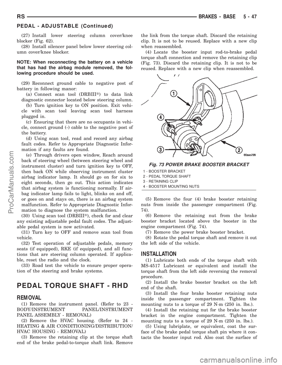
(27) Install lower steering column cover/knee
blocker (Fig. 62).
(28) Install silencer panel below lower steering col-
umn cover/knee blocker.
NOTE: When reconnecting the battery on a vehicle
that has had the airbag module removed, the fol-
lowing procedure should be used.
(29) Reconnect ground cable to negative post of
battery in following manor:
(a) Connect scan tool (DRBIIIt) to data link
diagnostic connector located below steering column.
(b) Turn ignition key to ON position. Exit vehi-
cle with scan tool leaving scan tool harness
plugged in.
(c) Ensuring that there are no occupants in vehi-
cle, connect ground (-) cable to the negative post of
the battery.
(d) Using scan tool, read and record any airbag
fault codes. Refer to Appropriate Diagnostic Infor-
mation if any faults are found.
(e) Through drivers open window, Reach around
back of steering wheel (between steering wheel and
instrument cluster) and turn ignition key to OFF,
then back ON while observing instrument cluster
airbag indicator lamp. It should go on for six to
eight seconds, then go out. This action indicates
that airbag system is functioning normally. If air-
bag indicator lamp fails to light, blinks on and off,
or goes on and stays on, there is an airbag system
malfunction. Refer to Appropriate Diagnostic Infor-
mation to diagnose the system malfunction.
(30) Using scan tool (DRBIIIt), check for and clear
any existing adjustable pedal fault codes. The adjust-
able pedal system is now activated.
(31) Turn key to OFF and remove scan tool from
vehicle.
(32) Test operation of adjustable pedals, memory
seats (if equipped), RKE (if equipped), and all func-
tions that are steering column operated. If applica-
ble, reset the radio and the clock.
(33) Road test the vehicle to ensure proper opera-
tion of the steering and brake systems.
PEDAL TORQUE SHAFT - RHD
REMOVAL
(1) Remove the instrument panel. (Refer to 23 -
BODY/INSTRUMENT PANEL/INSTRUMENT
PANEL ASSEMBLY - REMOVAL)
(2) Remove the HVAC housing. (Refer to 24 -
HEATING & AIR CONDITIONING/DISTRIBUTION/
HVAC HOUSING - REMOVAL)
(3) Remove the retaining clip at the torque shaft
end of the brake pedal-to-torque shaft link. Removethe link from the torque shaft. Discard the retaining
clip. It is not to be reused. Replace with a new clip
when reassembled.
(4) Locate the booster input rod-to-brake pedal
torque shaft connection and remove the retaining clip
(Fig. 73). Discard the retaining clip. It is not to be
reused. Replace with a new clip when reassembled.
(5) Remove the four (4) brake booster retaining
nuts from inside the passenger compartment (Fig.
74).
(6) Remove the retaining nut from the brake
booster bracket located above the booster in the
engine compartment (Fig. 74).
(7) Remove the power brake booster bracket.
(8) Rotate the pedal torque shaft and remove it out
the left side of the vehicle.
INSTALLATION
(1) Lubricate both ends of the torque shaft with
MS-4517 Lubricant or equivalent and install the
torque shaft from the left side reversing the removal
procedure.
(2) Install the brake booster bracket on the left
end of the shaft.
(3) Install the four brake booster retaining nuts
inside the passenger compartment. Tighten the
mounting nuts to a torque of 29 N´m (250 in. lbs.).
(4) Install the retaining nut for the brake booster
bracket in the engine compartment. Tighten the
mounting nuts to a torque of 29 N´m (250 in. lbs.).
(5) Using lubriplate, or equivalent, coat the sur-
face of the brake pedal torque shaft pin where it con-
tacts the booster input rod. Also coat the surface of
Fig. 73 POWER BRAKE BOOSTER BRACKET
1 - BOOSTER BRACKET
2 - PEDAL TORQUE SHAFT
3 - RETAINING CLIP
4 - BOOSTER MOUNTING NUTS
RSBRAKES - BASE5-47
PEDAL - ADJUSTABLE (Continued)
ProCarManuals.com
Page 177 of 2399

the brake pedal torque shaft pin where it contacts
the brake pedal link.
CAUTION: When installing the power brake booster
input rod on the brake pedal torque shaft pin, do
not reuse the old retaining clip.
(6) Install booster input rod on brake pedal torque
shaft pin and install a NEW retaining clip (Fig. 73).
CAUTION: When installing the brake pedal link on
the brake pedal torque shaft pin, do not reuse the
old retaining clip.
(7) Connect the brake pedal link to the torque
shaft. Install a NEW retaining clip at the torque
shaft end of the brake pedal-to-torque shaft link.
(8) Install the HVAC housing. (Refer to 24 - HEAT-
ING & AIR CONDITIONING/DISTRIBUTION/HVAC
HOUSING - INSTALLATION)
(9) Install the instrument panel. (Refer to 23 -
BODY/INSTRUMENT PANEL/INSTRUMENT
PANEL ASSEMBLY - INSTALLATION)CAUTION: Do not reuse the original brake lamp
switch. The switch can only be adjusted once. That
is during initial installation of the switch. If the
switch is not adjusted properly or has been
removed for some service, a new switch must be
installed and adjusted.
(10) Remove and replace the brake lamp switch
with a NEW switch. (Refer to 8 - ELECTRICAL/
LAMPS/LIGHTING - EXTERIOR/BRAKE LAMP
SWITCH - REMOVAL), (Refer to 8 - ELECTRICAL/
LAMPS/LIGHTING - EXTERIOR/BRAKE LAMP
SWITCH - INSTALLATION)
(11) Road test vehicle to ensure proper operation of
the brakes.
POWER BRAKE BOOSTER
DESCRIPTION
The power brake booster mounts on the engine
compartment side of the dash panel. It is connected
to the brake pedal by the input (push) rod (Fig. 75).
The master cylinder is bolted to the front of the
booster. A vacuum line connects the power brake
booster to the intake manifold.
Fig. 74 BOOSTER, TORQUE SHAFT AND PEDAL
MOUNTING
1 - PEDAL MOUNTING NUT
2 - BRAKE PEDAL ASSEMBLY
3 - PEDAL MOUNTING NUT
4 - PEDAL TORQUE SHAFT
5 - BOOSTER MOUNTING NUT
6 - BOOSTER BRACKET
7 - POWER BRAKE BOOSTER
8 - BOOSTER BRACKET MOUNTING NUT
Fig. 75 Power Brake Booster (Typical)
1 - VACUUM CHECK VALVE
2 - POWER BRAKE BOOSTER ASSEMBLY
3 - INPUT ROD
4 - POWER BOOSTER ASSEMBLY TO DASH PANEL MOUNTING
STUDS (4)
5 - MASTER CYLINDER MOUNTING STUDS (2)
6 - OUTPUT ROD
5 - 48 BRAKES - BASERS
PEDAL TORQUE SHAFT - RHD (Continued)
ProCarManuals.com
Page 180 of 2399

(15) Slide master cylinder straight out of power
brake booster. Remove master cylinder with primary
and secondary tubes from vehicle.
CAUTION: A seal on the rear of the master cylinder
is used to create the seal for holding vacuum in the
power brake vacuum booster. The vacuum seal on
the master cylinder MUST be replaced whenever the
master cylinder is removed from the power brake
vacuum booster.
(16) Disconnect vacuum hose from check valve
located on vacuum booster.DO NOT REMOVE
CHECK VALVE FROM POWER BRAKE
BOOSTER.
(17) Inside vehicle, remove silencer panel under
instrument panel below steering column.
(18) Locate the booster input rod to brake pedal
connection under the instrument panel. Position a
small screwdriver between the center tang on the
power brake booster input rod to brake pedal pin
retaining clip (Fig. 79).
(19) Rotate screwdriver enough to allow retaining
clip center tang to pass over end of brake pedal pin.
Then pull retaining clip off brake pedal pin.Discard
retaining clip. It is not to be reused. Replace
only with a new retaining clip when assem-
bling.
(20) Slide booster input rod off pedal pin.
(21) Remove the four nuts attaching power brake
booster to dash panel (Fig. 80).
(22) Slide power brake booster forward and remove
through engine compartment (Fig. 81).CAUTION: Do not attempt to disassemble the power
brake vacuum booster. It is serviced ONLY as a
complete assembly.
Fig. 78 Master Cylinder Mounting
1 - MASTER CYLINDER MOUNTING NUTS
2 - MASTER CYLINDER
3 - SECONDARY TUBE NUT AT ICU
4 - PRIMARY TUBE NUT AT ICU
Fig. 79 Vacuum Booster Input Rod Retaining Pin
1 - BRAKE PEDAL
2 - INPUT ROD
3 - SCREWDRIVER
4 - RETAINING CLIP
5 - BRAKE PEDAL PIN
Fig. 80 Booster Mounting
1 - DASH BRACKET
2 - POWER BRAKE BOOSTER
3 - BRAKE PEDAL ASSEMBLY
RSBRAKES - BASE5-51
POWER BRAKE BOOSTER (Continued)
ProCarManuals.com