transmission fluid CHRYSLER CARAVAN 2002 Workshop Manual
[x] Cancel search | Manufacturer: CHRYSLER, Model Year: 2002, Model line: CARAVAN, Model: CHRYSLER CARAVAN 2002Pages: 2399, PDF Size: 57.96 MB
Page 1581 of 2399
ries the governor and parking sprag. An integral heli-
cal gear on the transfer shaft drives the differential
ring gear.
OPERATION
Transmission output is directed to an integral dif-
ferential by a transfer gear system in the following
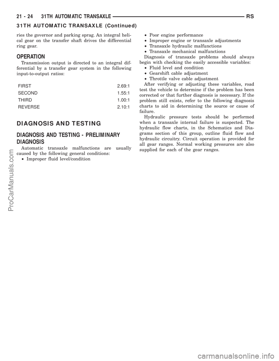
input-to-output ratios:
FIRST 2.69:1
SECOND 1.55:1
THIRD 1.00:1
REVERSE 2.10:1
DIAGNOSIS AND TESTING
DIAGNOSIS AND TESTING - PRELIMINARY
DIAGNOSIS
Automatic transaxle malfunctions are usually
caused by the following general conditions:
²Improper fluid level/condition²Poor engine performance
²Improper engine or transaxle adjustments
²Transaxle hydraulic malfunctions
²Transaxle mechanical malfunctions
Diagnosis of transaxle problems should always
begin with checking the easily accessible variables:
²Fluid level and condition
²Gearshift cable adjustment
²Throttle valve cable adjustment
After verifying or adjusting these variables, road
test the vehicle to determine if the problem has been
corrected or that further diagnosis is necessary. If the
problem still exists, refer to the following diagnosis
charts to aid in determining the source or cause of
failure.
Hydraulic pressure tests should be performed
when a transaxle internal failure is suspected. The
hydraulic flow charts, in the Schematics and Dia-
grams section of this group, outline fluid flow and
hydraulic circuitry. Circuit operation is provided for
all gear ranges. Normal working pressures are also
supplied for each of the gear ranges.
21 - 24 31TH AUTOMATIC TRANSAXLERS
31TH AUTOMATIC TRANSAXLE (Continued)
ProCarManuals.com
Page 1582 of 2399
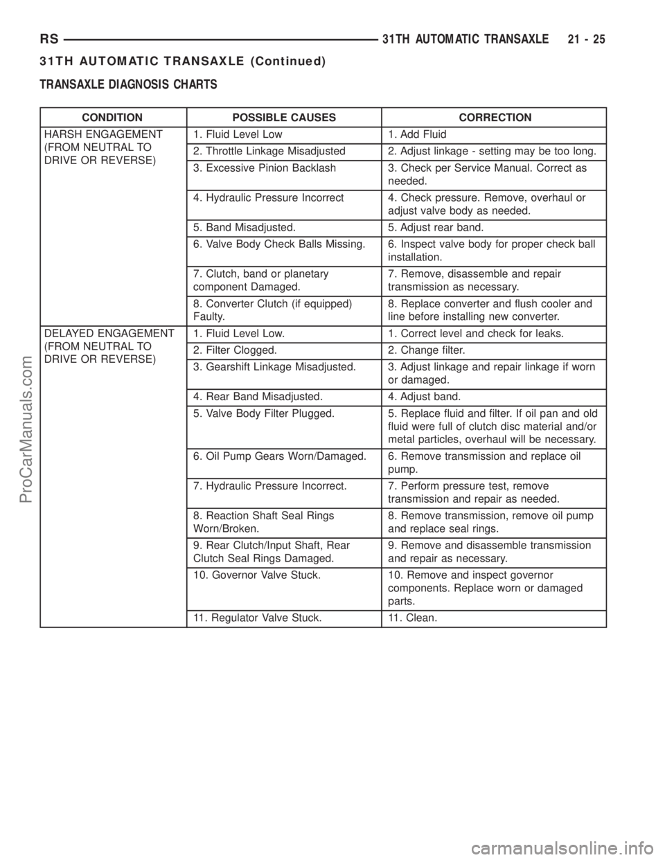
TRANSAXLE DIAGNOSIS CHARTS
CONDITION POSSIBLE CAUSES CORRECTION
HARSH ENGAGEMENT
(FROM NEUTRAL TO
DRIVE OR REVERSE)1. Fluid Level Low 1. Add Fluid
2. Throttle Linkage Misadjusted 2. Adjust linkage - setting may be too long.
3. Excessive Pinion Backlash 3. Check per Service Manual. Correct as
needed.
4. Hydraulic Pressure Incorrect 4. Check pressure. Remove, overhaul or
adjust valve body as needed.
5. Band Misadjusted. 5. Adjust rear band.
6. Valve Body Check Balls Missing. 6. Inspect valve body for proper check ball
installation.
7. Clutch, band or planetary
component Damaged.7. Remove, disassemble and repair
transmission as necessary.
8. Converter Clutch (if equipped)
Faulty.8. Replace converter and flush cooler and
line before installing new converter.
DELAYED ENGAGEMENT
(FROM NEUTRAL TO
DRIVE OR REVERSE)1. Fluid Level Low. 1. Correct level and check for leaks.
2. Filter Clogged. 2. Change filter.
3. Gearshift Linkage Misadjusted. 3. Adjust linkage and repair linkage if worn
or damaged.
4. Rear Band Misadjusted. 4. Adjust band.
5. Valve Body Filter Plugged. 5. Replace fluid and filter. If oil pan and old
fluid were full of clutch disc material and/or
metal particles, overhaul will be necessary.
6. Oil Pump Gears Worn/Damaged. 6. Remove transmission and replace oil
pump.
7. Hydraulic Pressure Incorrect. 7. Perform pressure test, remove
transmission and repair as needed.
8. Reaction Shaft Seal Rings
Worn/Broken.8. Remove transmission, remove oil pump
and replace seal rings.
9. Rear Clutch/Input Shaft, Rear
Clutch Seal Rings Damaged.9. Remove and disassemble transmission
and repair as necessary.
10. Governor Valve Stuck. 10. Remove and inspect governor
components. Replace worn or damaged
parts.
11. Regulator Valve Stuck. 11. Clean.
RS31TH AUTOMATIC TRANSAXLE21-25
31TH AUTOMATIC TRANSAXLE (Continued)
ProCarManuals.com
Page 1583 of 2399
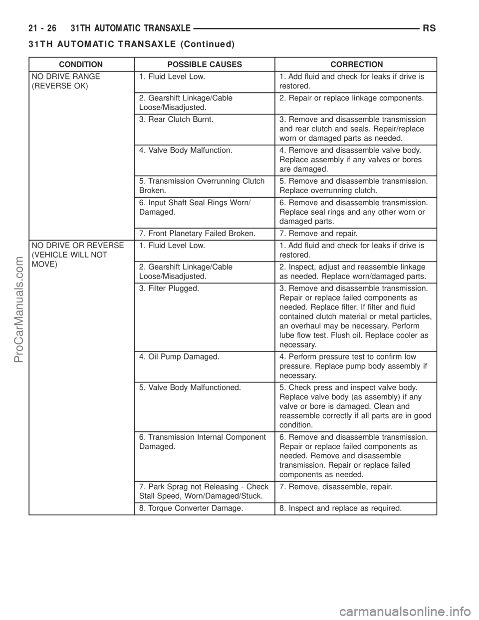
CONDITION POSSIBLE CAUSES CORRECTION
NO DRIVE RANGE
(REVERSE OK)1. Fluid Level Low. 1. Add fluid and check for leaks if drive is
restored.
2. Gearshift Linkage/Cable
Loose/Misadjusted.2. Repair or replace linkage components.
3. Rear Clutch Burnt. 3. Remove and disassemble transmission
and rear clutch and seals. Repair/replace
worn or damaged parts as needed.
4. Valve Body Malfunction. 4. Remove and disassemble valve body.
Replace assembly if any valves or bores
are damaged.
5. Transmission Overrunning Clutch
Broken.5. Remove and disassemble transmission.
Replace overrunning clutch.
6. Input Shaft Seal Rings Worn/
Damaged.6. Remove and disassemble transmission.
Replace seal rings and any other worn or
damaged parts.
7. Front Planetary Failed Broken. 7. Remove and repair.
NO DRIVE OR REVERSE
(VEHICLE WILL NOT
MOVE)1. Fluid Level Low. 1. Add fluid and check for leaks if drive is
restored.
2. Gearshift Linkage/Cable
Loose/Misadjusted.2. Inspect, adjust and reassemble linkage
as needed. Replace worn/damaged parts.
3. Filter Plugged. 3. Remove and disassemble transmission.
Repair or replace failed components as
needed. Replace filter. If filter and fluid
contained clutch material or metal particles,
an overhaul may be necessary. Perform
lube flow test. Flush oil. Replace cooler as
necessary.
4. Oil Pump Damaged. 4. Perform pressure test to confirm low
pressure. Replace pump body assembly if
necessary.
5. Valve Body Malfunctioned. 5. Check press and inspect valve body.
Replace valve body (as assembly) if any
valve or bore is damaged. Clean and
reassemble correctly if all parts are in good
condition.
6. Transmission Internal Component
Damaged.6. Remove and disassemble transmission.
Repair or replace failed components as
needed. Remove and disassemble
transmission. Repair or replace failed
components as needed.
7. Park Sprag not Releasing - Check
Stall Speed, Worn/Damaged/Stuck.7. Remove, disassemble, repair.
8. Torque Converter Damage. 8. Inspect and replace as required.
21 - 26 31TH AUTOMATIC TRANSAXLERS
31TH AUTOMATIC TRANSAXLE (Continued)
ProCarManuals.com
Page 1584 of 2399
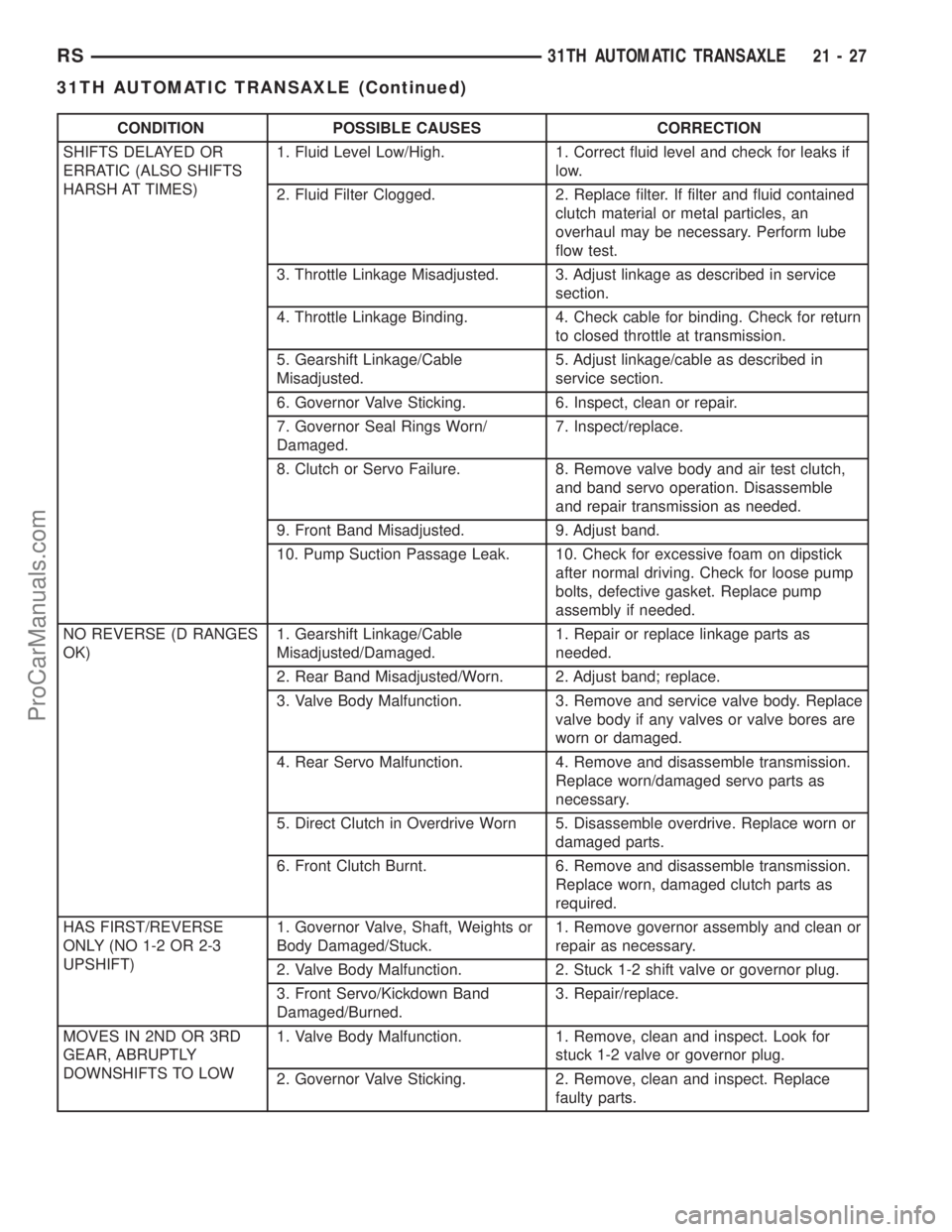
CONDITION POSSIBLE CAUSES CORRECTION
SHIFTS DELAYED OR
ERRATIC (ALSO SHIFTS
HARSH AT TIMES)1. Fluid Level Low/High. 1. Correct fluid level and check for leaks if
low.
2. Fluid Filter Clogged. 2. Replace filter. If filter and fluid contained
clutch material or metal particles, an
overhaul may be necessary. Perform lube
flow test.
3. Throttle Linkage Misadjusted. 3. Adjust linkage as described in service
section.
4. Throttle Linkage Binding. 4. Check cable for binding. Check for return
to closed throttle at transmission.
5. Gearshift Linkage/Cable
Misadjusted.5. Adjust linkage/cable as described in
service section.
6. Governor Valve Sticking. 6. Inspect, clean or repair.
7. Governor Seal Rings Worn/
Damaged.7. Inspect/replace.
8. Clutch or Servo Failure. 8. Remove valve body and air test clutch,
and band servo operation. Disassemble
and repair transmission as needed.
9. Front Band Misadjusted. 9. Adjust band.
10. Pump Suction Passage Leak. 10. Check for excessive foam on dipstick
after normal driving. Check for loose pump
bolts, defective gasket. Replace pump
assembly if needed.
NO REVERSE (D RANGES
OK)1. Gearshift Linkage/Cable
Misadjusted/Damaged.1. Repair or replace linkage parts as
needed.
2. Rear Band Misadjusted/Worn. 2. Adjust band; replace.
3. Valve Body Malfunction. 3. Remove and service valve body. Replace
valve body if any valves or valve bores are
worn or damaged.
4. Rear Servo Malfunction. 4. Remove and disassemble transmission.
Replace worn/damaged servo parts as
necessary.
5. Direct Clutch in Overdrive Worn 5. Disassemble overdrive. Replace worn or
damaged parts.
6. Front Clutch Burnt. 6. Remove and disassemble transmission.
Replace worn, damaged clutch parts as
required.
HAS FIRST/REVERSE
ONLY (NO 1-2 OR 2-3
UPSHIFT)1. Governor Valve, Shaft, Weights or
Body Damaged/Stuck.1. Remove governor assembly and clean or
repair as necessary.
2. Valve Body Malfunction. 2. Stuck 1-2 shift valve or governor plug.
3. Front Servo/Kickdown Band
Damaged/Burned.3. Repair/replace.
MOVES IN 2ND OR 3RD
GEAR, ABRUPTLY
DOWNSHIFTS TO LOW1. Valve Body Malfunction. 1. Remove, clean and inspect. Look for
stuck 1-2 valve or governor plug.
2. Governor Valve Sticking. 2. Remove, clean and inspect. Replace
faulty parts.
RS31TH AUTOMATIC TRANSAXLE21-27
31TH AUTOMATIC TRANSAXLE (Continued)
ProCarManuals.com
Page 1592 of 2399
DIAGNOSIS AND TESTING - TORQUE
CONVERTER HOUSING FLUID LEAKAGE
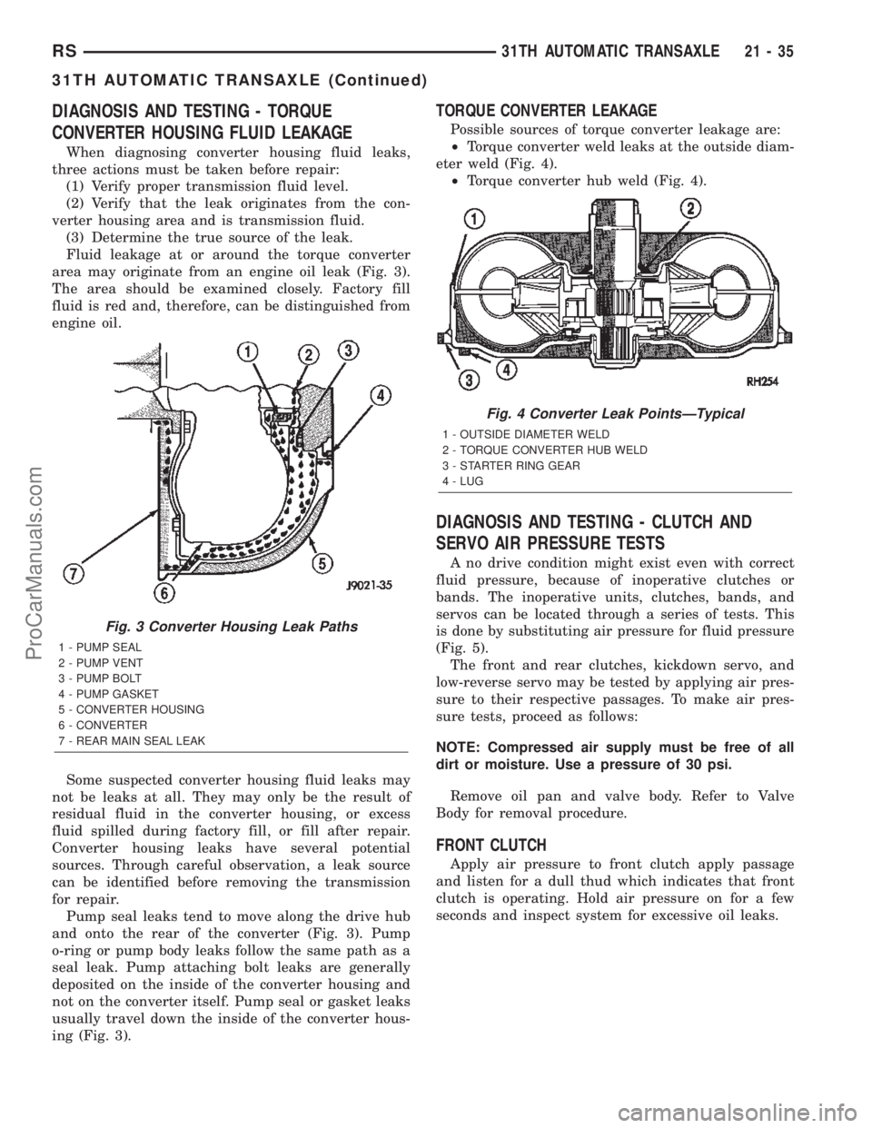
When diagnosing converter housing fluid leaks,
three actions must be taken before repair:
(1) Verify proper transmission fluid level.
(2) Verify that the leak originates from the con-
verter housing area and is transmission fluid.
(3) Determine the true source of the leak.
Fluid leakage at or around the torque converter
area may originate from an engine oil leak (Fig. 3).
The area should be examined closely. Factory fill
fluid is red and, therefore, can be distinguished from
engine oil.
Some suspected converter housing fluid leaks may
not be leaks at all. They may only be the result of
residual fluid in the converter housing, or excess
fluid spilled during factory fill, or fill after repair.
Converter housing leaks have several potential
sources. Through careful observation, a leak source
can be identified before removing the transmission
for repair.
Pump seal leaks tend to move along the drive hub
and onto the rear of the converter (Fig. 3). Pump
o-ring or pump body leaks follow the same path as a
seal leak. Pump attaching bolt leaks are generally
deposited on the inside of the converter housing and
not on the converter itself. Pump seal or gasket leaks
usually travel down the inside of the converter hous-
ing (Fig. 3).
TORQUE CONVERTER LEAKAGE
Possible sources of torque converter leakage are:
²Torque converter weld leaks at the outside diam-
eter weld (Fig. 4).
²Torque converter hub weld (Fig. 4).
DIAGNOSIS AND TESTING - CLUTCH AND
SERVO AIR PRESSURE TESTS
A no drive condition might exist even with correct
fluid pressure, because of inoperative clutches or
bands. The inoperative units, clutches, bands, and
servos can be located through a series of tests. This
is done by substituting air pressure for fluid pressure
(Fig. 5).
The front and rear clutches, kickdown servo, and
low-reverse servo may be tested by applying air pres-
sure to their respective passages. To make air pres-
sure tests, proceed as follows:
NOTE: Compressed air supply must be free of all
dirt or moisture. Use a pressure of 30 psi.
Remove oil pan and valve body. Refer to Valve
Body for removal procedure.
FRONT CLUTCH
Apply air pressure to front clutch apply passage
and listen for a dull thud which indicates that front
clutch is operating. Hold air pressure on for a few
seconds and inspect system for excessive oil leaks.
Fig. 3 Converter Housing Leak Paths
1 - PUMP SEAL
2 - PUMP VENT
3 - PUMP BOLT
4 - PUMP GASKET
5 - CONVERTER HOUSING
6 - CONVERTER
7 - REAR MAIN SEAL LEAK
Fig. 4 Converter Leak PointsÐTypical
1 - OUTSIDE DIAMETER WELD
2 - TORQUE CONVERTER HUB WELD
3 - STARTER RING GEAR
4 - LUG
RS31TH AUTOMATIC TRANSAXLE21-35
31TH AUTOMATIC TRANSAXLE (Continued)
ProCarManuals.com
Page 1620 of 2399

(13) Install halfshafts. (Refer to 3 - DIFFEREN-
TIAL & DRIVELINE/HALF SHAFT - INSTALLA-
TION)
(14) Lower vehicle.
(15) Torque rear mount bracket-to-transaxle verti-
cal bolts (Fig. 98) to 102 N´m (75 ft. lbs.).
(16) Connect back up lamp switch connector.
(17) Connect gearshift cable to manual valve and
left upper mount bracket (Fig. 102).
(18) Connect throttle valve cable to lever and
bracket (Fig. 103).
(19) Connect torque converter clutch connector.
(20) Install fluid level indicator/tube assembly
(Fig. 104).
(21) Raise vehicle on hoist.
(22) Torque rear mount bracket-to-transaxle case
horizontal bolt (Fig. 98) to 102 N´m (75 ft. lbs.).
(23) Torque rear mount thru-bolt to 54 N´m (40 ft.
lbs.).
(24) Lower vehicle.
(25) Connect battery negative cable.
(26) Fill transaxle with ATF+4 transmission fluid.
(Refer to 21 - TRANSMISSION/TRANSAXLE/AUTO-
MATIC - 31TH/FLUID - STANDARD PROCEDURE)
Fig. 102 Gearshift Cable at Transaxle
1 - MANUAL VALVE LEVER
2 - GEAR SHIFT CABLE
3 - UPPER MOUNT BRACKET
Fig. 103 Kickdown Cable at TransaxleÐTypical
1 - LEVER
2 - BRACKET
3 - THROTTLE VALVE CABLE
Fig. 104 Fluid Level Indicator Assembly
1 - INDICATOR ASSEMBLY
2 - BOLT
3 - KICKDOWN CABLE BRACKET
4 - SEAL
RS31TH AUTOMATIC TRANSAXLE21-63
31TH AUTOMATIC TRANSAXLE (Continued)
ProCarManuals.com
Page 1638 of 2399

(2) Remove transaxle oil pan and drain fluid (Fig.
111) (Fig. 112).
(3) Loosen band adjusting screw locknut 5-6 turns.
Be sure adjusting screw turns freely in lever.
(4) Tighten adjusting screw to 5 N´m (41 in. lbs.)
(Fig. 113).
(5) Back off adjusting screw 3
1¤2turns.
(6) Hold adjusting screw in place and tighten lock-
nut to 14 N´m (125 ft. lbs.) torque.
(7) Install a bead of MopartSilicone Rubber Adhe-
sive Sealant to the oil pan and install to case imme-
diately.
(8) Install oil pan-to-case bolts and torque to 19
N´m (165 in. lbs.).(9) Lower vehicle and refill transmission with
MopartATF Plus 4, Type 9602, fluid.
Fig. 110 Front (Kickdown) Band Adjustment
Location
1 - KICKDOWN BAND ADJUSTING SCREW
Fig. 111 Transaxle Oil Pan Bolts
1 - TRANSAXLE OIL PAN
2 - OIL PAN BOLTS
Fig. 112 Transaxle Oil Pan
1 - TRANSAXLE OIL PAN
2 - OIL FILTER
Fig. 113 Adjust Low/Reverse Band
1 - LOW-REVERSE BAND LEVER
2 - ADJUSTING SCREW
3 - STRUT
4 - LOW-REVERSE BAND
5 - LOCK NUT
6 - LEVER (SHORT)
RS31TH AUTOMATIC TRANSAXLE21-81
BANDS (Continued)
ProCarManuals.com
Page 1639 of 2399

CLUTCH - FRONT
DESCRIPTION
The front clutch assembly (Fig. 119) is composed of
the front clutch retainer, pressure plate, clutch
plates, driving discs, piston, piston return spring,
return spring retainer, and snap-rings. The front
clutch is the forward-most component in the trans-
mission geartrain and is directly behind the oil
pump. It is considered a driving component.
NOTE: The number of discs and plates may vary
with each engine and vehicle combination.
OPERATION
To apply the clutch, pressure is applied between
the clutch retainer and piston. The fluid pressure is
provided by the oil pump, transferred through the
control valves and passageways, and enters the
clutch through the hub of the reaction shaft support.
With pressure applied between the clutch retainer
and piston, the piston moves away from the clutch
retainer and compresses the clutch pack. This action
applies the clutch pack, allowing torque to flow
through the input shaft into the driving discs, and
into the clutch plates and pressure plate that are
lugged to the clutch retainer. The waved snap-ring is
used to cushion the application of the clutch pack. In
some transmissions, the snap-ring is selective and
used to adjust clutch pack clearance.
When pressure is released from the piston, the
spring returns the piston to its fully released position
and disengages the clutch. The release spring also
helps to cushion the application of the clutch assem-
bly. When the clutch is in the process of being
released by the release spring, fluid flows through a
vent and one-way ball-check-valve located in the
clutch retainer. The check-valve is needed to elimi-
nate the possibility of plate drag caused by centrifu-
gal force acting on the residual fluid trapped in the
clutch piston retainer.
DISASSEMBLY
(1) Remove front clutch waved snap ring using a
suitable screwdriver (Fig. 114).
(2) Remove waved snap ring and reaction plate
(Fig. 115).
Fig. 114 Front Clutch Waved Snap Ring
1 - WAVED SNAP RING
2 - SCREWDRIVER
3 - FRONT CLUTCH ASSEMBLY
Fig. 115 Thick Steel Plate and Waved Snap Ring
1 - WAVED SNAP RING
2 - THICK STEEL PLATE
3 - FRONT CLUTCH RETAINER
21 - 82 31TH AUTOMATIC TRANSAXLERS
ProCarManuals.com
Page 1643 of 2399

(5) Using feeler gauge, measure front clutch clear-
ance (Fig. 125).Front clutch clearance should be
within 1.27-2.79 mm (0.050-0.110 in.) and is not
adjustable.
CLUTCH - REAR
DESCRIPTION
The rear clutch assembly (Fig. 132) is composed of
the input shaft, rear clutch retainer, pressure plate,
clutch plates, driving discs, piston, Belleville spring,
and snap-rings. The Belleville spring acts as a lever
to multiply the force applied on to it by the apply pis-
ton. The increased apply force on the rear clutch
pack, in comparison to the front clutch pack, is
needed to hold against the greater torque load
imposed onto the rear pack. The rear clutch is
directly behind the front clutch and is considered a
driving component.
NOTE: The number of discs and plates may vary
with each engine and vehicle combination.
OPERATION
To apply the clutch, pressure is applied between
the clutch retainer and piston. The fluid pressure is
provided by the oil pump, transferred through the
control valves and passageways, and enters the
clutch through the hub of the reaction shaft support.
With pressure applied between the clutch retainer
and piston, the piston moves away from the clutch
retainer and compresses the clutch pack. This action
applies the clutch pack, allowing torque to flow
through the input shaft into the driving discs, and
into the clutch plates and pressure plate that are
lugged to the clutch retainer. The waved snap-ring is
used to cushion the application of the clutch pack. In
some transmissions, the snap-ring is selective and
used to adjust clutch pack clearance.
When pressure is released from the piston, the
spring returns the piston to its fully released position
and disengages the clutch. The release spring also
helps to cushion the application of the clutch assem-
bly. When the clutch is in the process of being
released by the release spring, fluid flows through a
vent and one-way ball-check-valve located in the
clutch retainer. The check-valve is needed to elimi-
nate the possibility of plate drag caused by centrifu-
gal force acting on the residual fluid trapped in the
clutch piston retainer.
Fig. 124 Front Clutch Waved Snap Ring
1 - WAVED SNAP RING
2 - SCREWDRIVER
3 - FRONT CLUTCH ASSEMBLY
Fig. 125 Measuring Front Clutch Plate Clearance
1 - FEELER GAUGE
2 - FRONT CLUTCH ASSEMBLY
21 - 86 31TH AUTOMATIC TRANSAXLERS
CLUTCH - FRONT (Continued)
ProCarManuals.com
Page 1656 of 2399
FLUID
STANDARD PROCEDURE
STANDARD PROCEDURE - FLUID LEVEL AND
CONDITION CHECK
NOTE: The transmission and differential sump have
a common oil sump with a communicating opening
between the two.
FLUID LEVEL CHECK
The torque converter fills in both the P Park and N
Neutral positions. Place the selector lever in P Park
to be sure that the fluid level check is accurate.The
engine should be running at idle speed for at
least one minute, with the vehicle on level
ground. This will assure complete oil level sta-
bilization between differential and transmis-
sion.The fluid should be at normal operating
temperature (approximately 82 C. or 180 F.). The
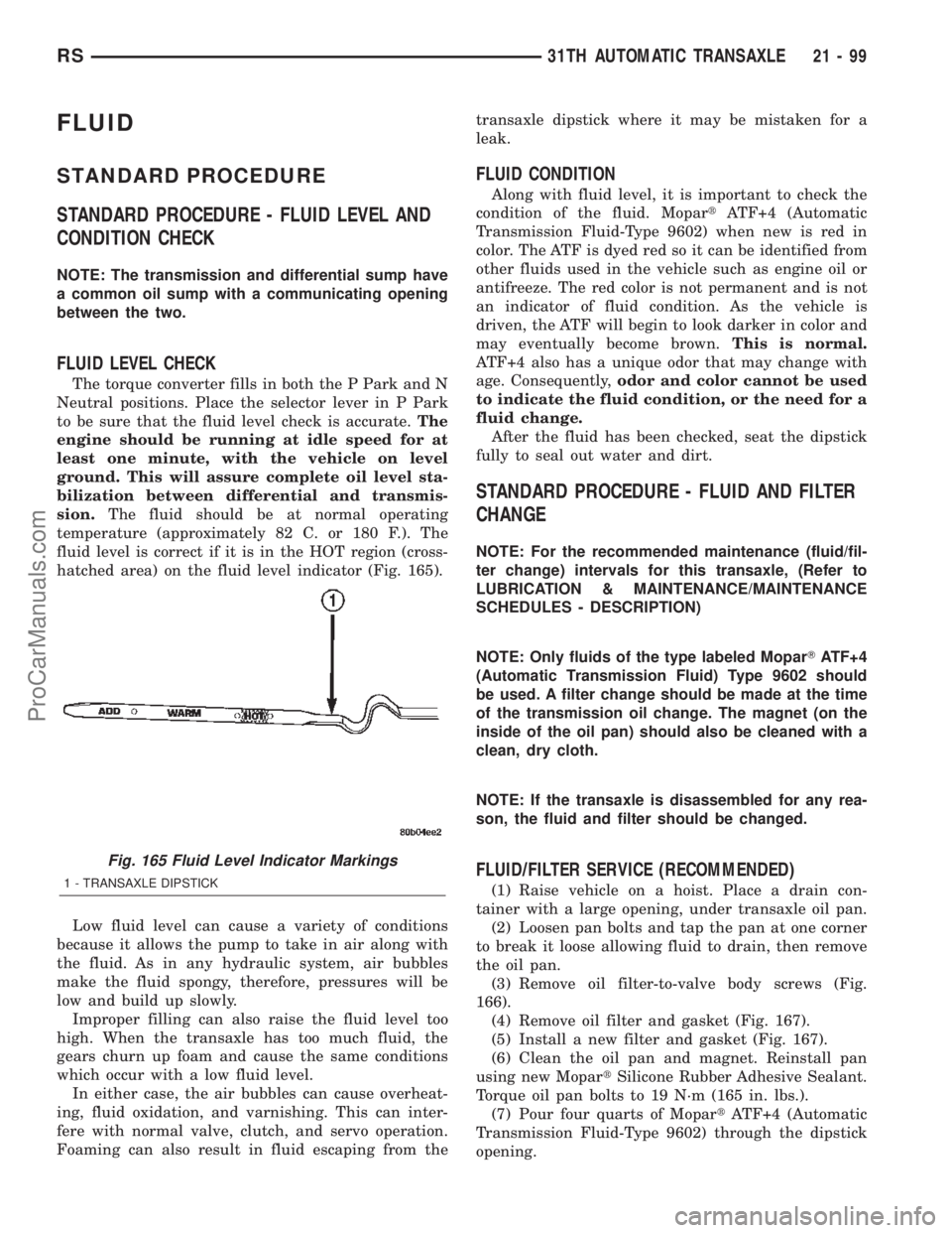
fluid level is correct if it is in the HOT region (cross-
hatched area) on the fluid level indicator (Fig. 165).
Low fluid level can cause a variety of conditions
because it allows the pump to take in air along with
the fluid. As in any hydraulic system, air bubbles
make the fluid spongy, therefore, pressures will be
low and build up slowly.
Improper filling can also raise the fluid level too
high. When the transaxle has too much fluid, the
gears churn up foam and cause the same conditions
which occur with a low fluid level.
In either case, the air bubbles can cause overheat-
ing, fluid oxidation, and varnishing. This can inter-
fere with normal valve, clutch, and servo operation.
Foaming can also result in fluid escaping from thetransaxle dipstick where it may be mistaken for a
leak.
FLUID CONDITION
Along with fluid level, it is important to check the
condition of the fluid. MopartATF+4 (Automatic
Transmission Fluid-Type 9602) when new is red in
color. The ATF is dyed red so it can be identified from
other fluids used in the vehicle such as engine oil or
antifreeze. The red color is not permanent and is not
an indicator of fluid condition. As the vehicle is
driven, the ATF will begin to look darker in color and
may eventually become brown.This is normal.
ATF+4 also has a unique odor that may change with
age. Consequently,odor and color cannot be used
to indicate the fluid condition, or the need for a
fluid change.
After the fluid has been checked, seat the dipstick
fully to seal out water and dirt.
STANDARD PROCEDURE - FLUID AND FILTER
CHANGE
NOTE: For the recommended maintenance (fluid/fil-
ter change) intervals for this transaxle, (Refer to
LUBRICATION & MAINTENANCE/MAINTENANCE
SCHEDULES - DESCRIPTION)
NOTE: Only fluids of the type labeled MoparTATF+4
(Automatic Transmission Fluid) Type 9602 should
be used. A filter change should be made at the time
of the transmission oil change. The magnet (on the
inside of the oil pan) should also be cleaned with a
clean, dry cloth.
NOTE: If the transaxle is disassembled for any rea-
son, the fluid and filter should be changed.
FLUID/FILTER SERVICE (RECOMMENDED)
(1) Raise vehicle on a hoist. Place a drain con-
tainer with a large opening, under transaxle oil pan.
(2) Loosen pan bolts and tap the pan at one corner
to break it loose allowing fluid to drain, then remove
the oil pan.
(3) Remove oil filter-to-valve body screws (Fig.
166).
(4) Remove oil filter and gasket (Fig. 167).
(5) Install a new filter and gasket (Fig. 167).
(6) Clean the oil pan and magnet. Reinstall pan
using new MopartSilicone Rubber Adhesive Sealant.
Torque oil pan bolts to 19 N´m (165 in. lbs.).
(7) Pour four quarts of MopartATF+4 (Automatic
Transmission Fluid-Type 9602) through the dipstick
opening.
Fig. 165 Fluid Level Indicator Markings
1 - TRANSAXLE DIPSTICK
RS31TH AUTOMATIC TRANSAXLE21-99
ProCarManuals.com