washer fluid CHRYSLER CARAVAN 2002 Workshop Manual
[x] Cancel search | Manufacturer: CHRYSLER, Model Year: 2002, Model line: CARAVAN, Model: CHRYSLER CARAVAN 2002Pages: 2399, PDF Size: 57.96 MB
Page 1845 of 2399

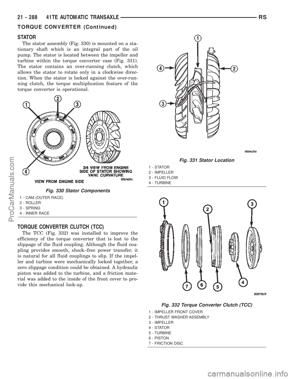
STATOR
The stator assembly (Fig. 330) is mounted on a sta-
tionary shaft which is an integral part of the oil
pump. The stator is located between the impeller and
turbine within the torque converter case (Fig. 331).
The stator contains an over-running clutch, which
allows the stator to rotate only in a clockwise direc-
tion. When the stator is locked against the over-run-
ning clutch, the torque multiplication feature of the
torque converter is operational.
TORQUE CONVERTER CLUTCH (TCC)
The TCC (Fig. 332) was installed to improve the
efficiency of the torque converter that is lost to the
slippage of the fluid coupling. Although the fluid cou-
pling provides smooth, shock±free power transfer, it
is natural for all fluid couplings to slip. If the impel-
ler and turbine were mechanically locked together, a
zero slippage condition could be obtained. A hydraulic
piston was added to the turbine, and a friction mate-
rial was added to the inside of the front cover to pro-
vide this mechanical lock-up.
Fig. 330 Stator Components
1 - CAM (OUTER RACE)
2 - ROLLER
3 - SPRING
4 - INNER RACE
Fig. 331 Stator Location
1-STATOR
2 - IMPELLER
3 - FLUID FLOW
4 - TURBINE
Fig. 332 Torque Converter Clutch (TCC)
1 - IMPELLER FRONT COVER
2 - THRUST WASHER ASSEMBLY
3 - IMPELLER
4-STATOR
5 - TURBINE
6 - PISTON
7 - FRICTION DISC
21 - 288 41TE AUTOMATIC TRANSAXLERS
TORQUE CONVERTER (Continued)
ProCarManuals.com
Page 1915 of 2399

ADJUSTMENT - DIFFERENTIAL SIDE GEAR
END PLAY
Measure side gear end play: Insert feeler gauges
180É apart between differential side gear and thrust
washer as shown in (Fig. 124). Measurement taken
here applies to both sides. Side gear end play should
be between 0.025-0.152 mm (0.001-0.006 in.). If clear-
ance is greater than 0.152 mm (0.006 in.), install a
thicker thrust washer (both sides). If clearance is less
than 0.025 mm (0.001), install a thinner thrust
washer (both sides). Refer to (Fig. 125) for available
side gear shim thicknesses.
If end play measurement indicates a thrust washer
change is necessary, the differential must be disas-
sembled. (Refer to 21 - TRANSMISSION/TRANS-
AXLE/MANUAL/DIFFERENTIAL - DISASSEMBLY)
FLUID
STANDARD PROCEDURE
STANDARD PROCEDURE - FLUID LEVEL
CHECK
NOTE: For proper fluid level check intervals, (Refer
to LUBRICATION & MAINTENANCE/MAINTENANCE
SCHEDULES - DESCRIPTION)
The fluid required in this transaxle is Mopart
ATF+4 (Automatic Transmission FluidÐType 9602).
Use of substitute fluids may result in improper
transaxle operation and/or failure.
(1) Raise vehicle on hoist.(2) Remove transaxle fill plug (Fig. 126).
(3) Inspect fluid level. Fluid should be within 1/8º
below fill hole. Add MopartATF+4 (Automatic Trans-
mission FluidÐType 9602) as neccessary.
(4) Install fill plug, ensuring it is properly seated.
(5) Lower vehicle.
Fig. 124 Side Gear End Play Measurement
1 - FEELER GAUGE
Fig. 125 Available Side Gear Thrust Washers
1 - (PLAIN) 0.79-0.84 mm (0.031-0.033 in.)
2 - ( TRIANGLE) 0.91-0.97 mm (0.036-0.038 in.)
3 - (SQUARE) 1.04-1.10 mm (0.041-0.043 in.)
4 - (DIAMOND) 1.17-1.22 mm (0.046-0.048 in.)
Fig. 126 Transaxle Fill Plug
1 - FILL PLUG
2 - END COVER
21 - 358 T850 MANUAL TRANSAXLERS
DIFFERENTIAL (Continued)
ProCarManuals.com
Page 2380 of 2399

(2) Disconnect the fresh air makeup hose on rear
valve cover.
(3) Remove the air box bolt.
(4) Remove the hose clamp at throttle body.
(5) Unlatch 2 clamps for air box cover.
(6) Remove air box cover.
(7) Disconnect the washer fluid fill hose.
(8) Remove air box.
(9) Remove the 2 bolts at the EGR valve.
(10) Remove the 2 bolts at the intake manifold.
(11) Remove front EGR tube.
REMOVAL - REAR TUBE - 3.5L
(1) Remove the battery, refer to the Battery sec-
tion.
(2) Remove the Battery tray/vacuum reservoir.
(3) Remove the speed control servo and bracket
and relocate.
(4) Remove the 2 bolts from the EGR valve.
(5) Remove the 2 bolts from the rear cylinder
head.
(6) Remove the EGR rear tube.
INSTALLATION
INSTALLATION - 2.4L
(1) Loose install EGR tube and gasket with attach-
ing bolts at intake manifold.
(2) Loose install EGR tube and gasket with attach-
ing bolts at EGR valve.
(3) Tighten bolts to EGR valve to 11.9 N´m (105
20 ins. lbs.).
(4) Tighten bolts to Intake manifold to 11.9 N´m
(105 20 ins. lbs.).
INSTALLATION - FRONT TUBE - 3.5L
(1) Install front EGR tube and gaskets.
(2) Install the 2 bolts at the EGR valve.
(3) Install the 2 bolts at the intake manifold.
(4) Tighten all 4 bolts.
(5) Install air box.
(6) Connect the washer fluid fill hose.
(7) Install air box cover.
(8) Latch 2 clamps for air box cover.
(9) Install the hose clamp at throttle body.
(10) Install the air box bolt.
(11) Connect the fresh air makeup hose on rear
valve cover.
(12) Connect the negative battery cable.
INSTALLATION - REAR TUBE - 3.5L
(1) Install the EGR rear tube.
(2) Install the 2 bolts to the rear cylinder head.
(3) Install the 2 bolts to the EGR valve.
(4) Tighten the 4 bolts.(5) Install the speed control servo and bracket,
refer to the speed control section.
(6) Install the Battery tray/vacuum reservoir refer
to the battery section.
(7) Install the battery, refer to the Battery section.
VA LV E
DESCRIPTION
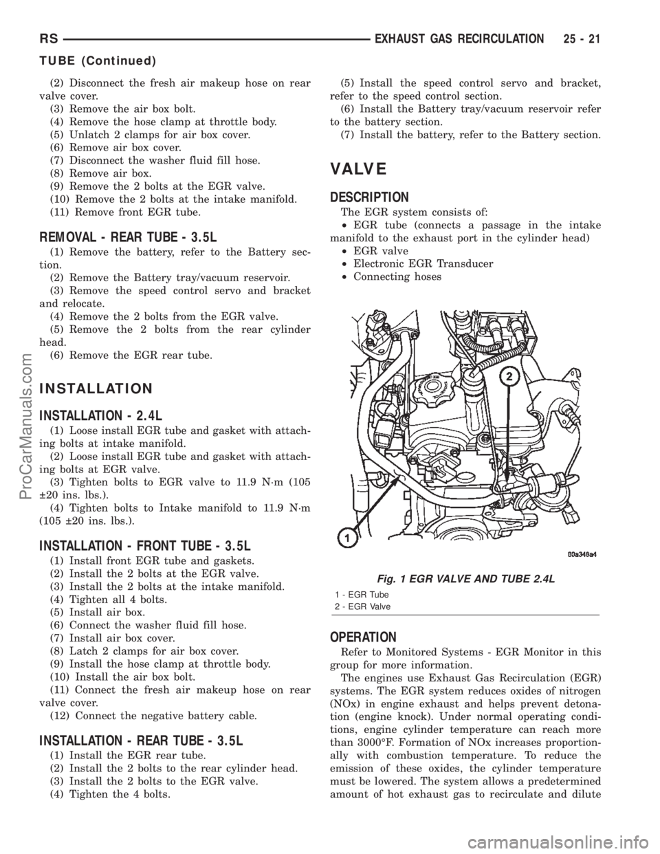
The EGR system consists of:
²EGR tube (connects a passage in the intake
manifold to the exhaust port in the cylinder head)
²EGR valve
²Electronic EGR Transducer
²Connecting hoses
OPERATION
Refer to Monitored Systems - EGR Monitor in this
group for more information.
The engines use Exhaust Gas Recirculation (EGR)
systems. The EGR system reduces oxides of nitrogen
(NOx) in engine exhaust and helps prevent detona-
tion (engine knock). Under normal operating condi-
tions, engine cylinder temperature can reach more
than 3000ÉF. Formation of NOx increases proportion-
ally with combustion temperature. To reduce the
emission of these oxides, the cylinder temperature
must be lowered. The system allows a predetermined
amount of hot exhaust gas to recirculate and dilute
Fig. 1 EGR VALVE AND TUBE 2.4L
1 - EGR Tube
2 - EGR Valve
RSEXHAUST GAS RECIRCULATION25-21
TUBE (Continued)
ProCarManuals.com