diagram CHRYSLER CARAVAN 2002 Repair Manual
[x] Cancel search | Manufacturer: CHRYSLER, Model Year: 2002, Model line: CARAVAN, Model: CHRYSLER CARAVAN 2002Pages: 2399, PDF Size: 57.96 MB
Page 605 of 2399
POWER WINDOWS
TABLE OF CONTENTS
page page
POWER WINDOWS
DESCRIPTION.........................64
OPERATION...........................64
DIAGNOSIS AND TESTING - POWER
WINDOWS...........................64
VENT WINDOW MOTOR
DIAGNOSIS AND TESTING - VENT WINDOW
MOTOR .............................65
REMOVAL.............................65INSTALLATION.........................65
WINDOW MOTOR
REMOVAL.............................66
WINDOW SWITCH
DIAGNOSIS AND TESTING - WINDOW
SWITCH............................66
REMOVAL.............................67
INSTALLATION.........................67
POWER WINDOWS
DESCRIPTION
The Power Window System is activated through
switches mounted on the driver and passenger door
panels.
OPERATION
Front door window lift motors use permanent type
magnets. The B+ and ground applied at the motor
terminal pins will cause the motor to rotate in one
direction. Reversing current through the motor ter-
minals will cause the motor to rotate in the opposite
direction.
The power window motors ground through the
master switch in the driver door by a black wire
attached to the left cowl panel. Refer to the appropri-
ate wiring information. The wiring information
includes wiring diagrams, proper wire and connector
repair procedures, details of wire harness routing
and retention, connector pin-out information and
location views for the various wire harness connec-
tors, splices and grounds.
The power rear vent windows, if equipped, are
operated by switches mounted in the driver door
switch bezel. A separate switch is used for each win-
dow. Permanent magnet type motors connected to a
crank system are used to open and close the rear
vent windows. A battery positive and negative con-
nection to either of the two motor terminals will
cause the motor to rotate in one direction. Reversing
current through these same two connections will
cause the motor to rotate in the opposite direction.
Refer to the appropriate wiring information. The wir-
ing information includes wiring diagrams, proper
wire and connector repair procedures, details of wire
harness routing and retention, connector pin-outinformation and location views for the various wire
harness connectors, splices and grounds.
DIAGNOSIS AND TESTING - POWER
WINDOWS
POWER WINDOW MOTOR TEST
If the power window motor is receiving proper cur-
rent and ground and does not operate, proceed with
motor test. Refer to the appropriate wiring informa-
tion. The wiring information includes wiring dia-
grams, proper wire and connector repair procedures,
details of wire harness routing and retention, connec-
tor pin-out information and location views for the
various wire harness connectors, splices and grounds.
(1) Remove front door trim panel and sound pad as
necessary to gain access to power window motor wire
connector, (Refer to 23 - BODY/DOOR - FRONT/
TRIM PANEL - REMOVAL).
(2) Disconnect power window motor wire connector
from door harness.
(3) Using two jumper wires, connect one to a bat-
tery (+) source and the other to a good ground (-).
(4) Connect the Negative (-) jumper probe to one of
the motor connector terminals.
(5) Momentarily touch the Positive (+) jumper
probe to the other motor connector terminal.
When positive probe is connected the motor should
rotate in one direction to either move window up or
down. If window is all the way up or down the motor
will grunt and the inner door panel will flex when
actuated in that one direction.
(6) Reverse jumper probes at the motor connector
terminals and window should now move in opposite
direction. If window does not move or grunt, replace
the motor.
8N - 64 POWER WINDOWSRS
ProCarManuals.com
Page 606 of 2399
If window moved completely up or down, reverse
the jumper probes and cycle window to the opposite
position to verify full operation.
If motor grunts and does not move, verify that reg-
ulator is not binding.
WIRING VOLTAGE TEST
The following wiring test determines whether or
not voltage is continuous through the body harness
to switch.
(1) Remove the power window switch and bezel
assembly from the driver door. (Refer to 8 - ELEC-
TRICAL/POWER WINDOWS/POWER WINDOW
SWITCH - REMOVAL).
(2) Disconnect wire connector from back of power
window switch.
(3) Switch ignition ON position.
(4) Connect the clip end of a 12 volt test light to
Pin 13 in door harness connector at the window
switch. Touch the test light probe to Pin 9 and then
to Pin 11.
²If the test light illuminates, the wiring circuit
between the battery and switch is OK.
²If the lamp does not illuminate, first check the
25 amp circuit breaker attached to the electrical dis-
tribution wiring bracket. If the circuit breaker is OK,
then check the 40 amp fuse (#28) in the Integrated
Power Module (IPM). If both components are OK,
then check for a broken wire.
²Refer to the appropriate wiring information.
The wiring information includes wiring diagrams,
proper wire and connector repair procedures, details
of wire harness routing and retention, connector pin-
out information and location views for the various
wire harness connectors, splices and grounds.
VENT WINDOW MOTOR
DIAGNOSIS AND TESTING - VENT WINDOW
MOTOR
If the power vent window motor is receiving proper
current and ground and does not operate proceed
with motor test. Refer to the appropriate wiring
information. The wiring information includes wiring
diagrams, proper wire and connector repair proce-
dures, details of wire harness routing and retention,
connector pin-out information and location views for
the various wire harness connectors, splices and
grounds.
(1) Remove D-pillar trim panel necessary to gain
access to power vent window motor wire connector,
(Refer to 23 - BODY/INTERIOR/LEFT D-PILLAR
TRIM PANEL - REMOVAL) or (Refer to 23 - BODY/
INTERIOR/RIGHT D-PILLAR TRIM PANEL -
REMOVAL).(2) Disconnect power vent window motor wire con-
nector from body harness.
(3) Using two jumper wires, connect one to a bat-
tery (+) source and the other to a good ground (-).
(4) Connect the Negative (-) jumper probe to one of
the motor connector terminals.
(5) Momentarily touch the Positive (+) jumper
probe to the other motor connector terminal.
When positive probe is connected the motor should
rotate in one direction to either move window open or
closed. If window is all the way open or closed the
motor will grunt and the crank system will flex when
actuated in that one direction.
Reverse jumper probes at the motor connector ter-
minals and window should now move in opposite
direction. If window does not move or grunt, replace
the motor.
If window moved completely open or closed, reverse
the jumper probes and cycle window to the opposite
position to verify full operation.
If motor grunts and does not move, verify that
crank system is not binding.
REMOVAL
(1) Disconnect and isolate the battery negative
cable.
(2) Remove D-pillar trim panel. (Refer to 23 -
BODY/INTERIOR/LEFT D-PILLAR TRIM PANEL -
REMOVAL) or (Refer to 23 - BODY/INTERIOR/
RIGHT D-PILLAR TRIM PANEL - REMOVAL).
(3) Disconnect wire connector from power vent
motor.
(4) Using a flat bladed tool, carefully lift the circu-
lar actuator link tab. Remove link from window ball
socket.
(5) Remove bolts holding power vent motor to
D-pillar (Fig. 1).
(6) Remove power vent motor.
INSTALLATION
(1) Obtain new vent window motor.
(2) Snap the actuator link socket onto the quarter
window ball socket. Using a soft rubber mallet, push
the circular link tab flush with link surface.
(3) Install bolts holding power vent motor to D-pil-
lar.
(4) Reconnect wire connector to power vent motor.
(5) Reconnect the battery negative cable.
(6) Cycle quarter window open/close to verify func-
tion.
(7) Install D-pillar trim panel.
RSPOWER WINDOWS8N-65
POWER WINDOWS (Continued)
ProCarManuals.com
Page 634 of 2399
DIAGNOSIS AND TESTING
DIAGNOSIS AND TESTING - SENTRY KEY
IMMOBILIZER SYSTEM
WARNING: ON VEHICLES EQUIPPED WITH AIR-
BAGS, REFER TO ELECTRICAL, RESTRAINTS,
WARNINGS, BEFORE ATTEMPTING COMPONENT
DIAGNOSIS OR SERVICE. FAILURE TO TAKE THE
PROPER PRECAUTIONS COULD RESULT IN ACCI-
DENTAL AIRBAG DEPLOYMENT AND POSSIBLE
PERSONAL INJURY.
NOTE: The following tests may not prove conclu-
sive in the diagnosis of this system. The most reli-
able, efficient, and accurate means to diagnose the
Sentry Key Immobilizer System involves the use of
a DRB IIITscan tool. Refer to the proper Body Diag-
nostic Procedures Manual.
The Sentry Key Immobilizer System (SKIS) and
the Programmable Communication Interface (PCI)
bus network should be diagnosed using a DRB IIIt
scan tool. The DRB IIItwill allow confirmation that
the PCI bus is functional, that the Sentry Key Immo-
bilizer Module (SKIM) is placing the proper messages
on the PCI bus, and that the Powertrain Control
Module (PCM) is receiving the PCI bus messages.
Refer to the proper Body Diagnostic Procedures man-
ual, and Wiring Diagrams for complete circuit
descriptions and diagrams.
(1) Check the fuses in the Integrated Power Mod-
ule (IPM). If OK, go to Step 2. If not OK, repair the
shorted circuit or component as required and replace
the faulty fuse.
(2) Disconnect and isolate the battery negative
remote cable from the remote terminal. Unplug the
wire harness connector at the SKIM. Check for con-
tinuity between the ground circuit cavity of the
SKIM wire harness connector and a good ground.
There should be continuity. If OK, go to Step 3. If not
OK, repair the open circuit to ground as required.
(3) Connect the battery negative cable. Check for
battery voltage at the fused B(+) circuit cavity of the
SKIM wire harness connector. If OK, go to Step 4. If
not OK, repair the open circuit to the fuse in the
IPM as required.
(4) Turn the ignition switch to the ON position.
Check for battery voltage at the fused ignition switch
output (run/start) circuit cavity of the SKIM wire
harness connector. If OK, use a DRB IIItscan tool
and the proper Body Diagnostic Procedures manual
to complete the diagnosis of the SKIS. If not OK,
repair the open circuit to the fuse in the IPM as
required.
DIAGNOSIS AND TESTING - VEHICLE THEFT
SECURITY SYSTEM
Refer to the appropriate wiring information. The
wiring information includes wiring diagrams, proper
wire and connector repair procedures, further details
on wire harness routing and retention, as well as
pin-out and location views for the various wire har-
ness connectors, splices and grounds. Using a DRB
IIItscan tool. Refer to the proper Body Diagnostic
Procedures Manual for test procedures.
HOOD AJAR SWITCH
REMOVAL
(1) Disconnect and isolate the battery negative
cable.
(2) Using a small flat blade screwdriver, pry trig-
ger switch from the bracket on the left fender well.
(3) Disconnect the hood ajar switch from the wire
connector and remove from vehicle.
INSTALLATION
(1) Connect the hood ajar switch to the wire conec-
tor.
(2) Press the hood ajar switch into position on the
bracket located on the left inner fender well.
(3) Reconnect the battery negative cable.
(4) Close the hood and check for proper operation.
TRANSPONDER KEY
DESCRIPTION
The Sentry Key Immobilizer System (SKIS) uses a
transponder chip that is integral to each ignition key
(Fig. 1) to communicate with the Sentry Key Immo-
bilizer Module (SKIM). Ignition keys are supplied
with the vehicle when it is shipped from the factory.
The transponder chip is undermolded within the
head of the key. This undermold is hidden beneath
an overmolded rubber cap.
OPERATION
Each Sentry Key has a unique transponder identi-
fication code permanently programmed into it by the
manufacturer. Likewise, the SKIM has a unique
9Secret Key9code programmed into it by the manu-
facturer as well. When a Sentry Key is programmed
into the memory of the SKIM, the SKIM stores the
transponder identification code from the Sentry Key,
and the Sentry Key learns the9Secret Key9code from
the SKIM. Once the Sentry Key learns the9Secret
Key9code of the SKIM, it is also permanently pro-
grammed into the transponder's memory. Therefore,
blank keys for the SKIS must be programmed by the
RSVEHICLE THEFT SECURITY8Q-3
VEHICLE THEFT SECURITY (Continued)
ProCarManuals.com
Page 641 of 2399
CONDITION POSSIBLE CAUSES CORRECTION
3. BLADE STRUCTURE BENT. 3. REPLACE BLADE.
4. BLADE ELEMENT HAS
PERMANENT SET.4. REPLACE BLADE.
WIPER KNOCK AT
REVERSAL1. LINKAGE BUSHINGS WORN. 1. REPLACE WORN LINK. REFER TO
WIPER LINKAGE REMOVAL AND
INSTALLATION.
2. ARMATURE ENDPLAY IN
MOTOR.2. REPLACE WIPER MOTOR. REFER TO
WIPER MOTOR REMOVAL AND
INSTALLATION.
WIPER MOTOR WILL NOT
RUN1. BLOWN FUSE. 1. REPLACE FUSE, AND RUN SYSTEM.
2. NEW FUSE BLOWS. 2. CHECK FOR SHORT IN WIRING OR
SWITCH.
3. NEW FUSE BLOWS. 3. REPLACE FUSE, REMOVE MOTOR
CONNECTOR, TURN SWITCH ON, FUSE
DOES NOT BLOW, REPLACE MOTOR.
4. NO VOLTAGE AT MOTOR. 4. CHECK SWITCH AND WIRING
HARNESS. REFER TO WIRING
DIAGRAMS.
5. POOR GROUND. 5. REPAIR GROUND WIRE CONNECTION
AS NECESSARY.
8R - 4 WIPERS/WASHERSRS
WIPERS/WASHERS (Continued)
ProCarManuals.com
Page 642 of 2399
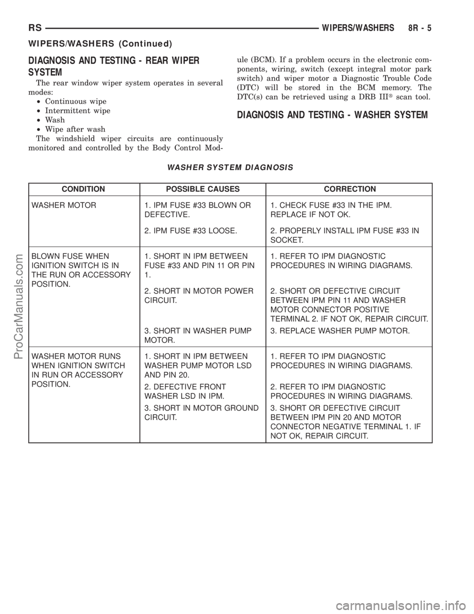
DIAGNOSIS AND TESTING - REAR WIPER
SYSTEM
The rear window wiper system operates in several
modes:
²Continuous wipe
²Intermittent wipe
²Wash
²Wipe after wash
The windshield wiper circuits are continuously
monitored and controlled by the Body Control Mod-ule (BCM). If a problem occurs in the electronic com-
ponents, wiring, switch (except integral motor park
switch) and wiper motor a Diagnostic Trouble Code
(DTC) will be stored in the BCM memory. The
DTC(s) can be retrieved using a DRB IIItscan tool.
DIAGNOSIS AND TESTING - WASHER SYSTEM
WASHER SYSTEM DIAGNOSIS
CONDITION POSSIBLE CAUSES CORRECTION
WASHER MOTOR 1. IPM FUSE #33 BLOWN OR
DEFECTIVE.1. CHECK FUSE #33 IN THE IPM.
REPLACE IF NOT OK.
2. IPM FUSE #33 LOOSE. 2. PROPERLY INSTALL IPM FUSE #33 IN
SOCKET.
BLOWN FUSE WHEN
IGNITION SWITCH IS IN
THE RUN OR ACCESSORY
POSITION.1. SHORT IN IPM BETWEEN
FUSE #33 AND PIN 11 OR PIN
1.1. REFER TO IPM DIAGNOSTIC
PROCEDURES IN WIRING DIAGRAMS.
2. SHORT IN MOTOR POWER
CIRCUIT.2. SHORT OR DEFECTIVE CIRCUIT
BETWEEN IPM PIN 11 AND WASHER
MOTOR CONNECTOR POSITIVE
TERMINAL 2. IF NOT OK, REPAIR CIRCUIT.
3. SHORT IN WASHER PUMP
MOTOR.3. REPLACE WASHER PUMP MOTOR.
WASHER MOTOR RUNS
WHEN IGNITION SWITCH
IN RUN OR ACCESSORY
POSITION.1. SHORT IN IPM BETWEEN
WASHER PUMP MOTOR LSD
AND PIN 20.1. REFER TO IPM DIAGNOSTIC
PROCEDURES IN WIRING DIAGRAMS.
2. DEFECTIVE FRONT
WASHER LSD IN IPM.2. REFER TO IPM DIAGNOSTIC
PROCEDURES IN WIRING DIAGRAMS.
3. SHORT IN MOTOR GROUND
CIRCUIT.3. SHORT OR DEFECTIVE CIRCUIT
BETWEEN IPM PIN 20 AND MOTOR
CONNECTOR NEGATIVE TERMINAL 1. IF
NOT OK, REPAIR CIRCUIT.
RSWIPERS/WASHERS8R-5
WIPERS/WASHERS (Continued)
ProCarManuals.com
Page 643 of 2399

CONDITION POSSIBLE CAUSES CORRECTION
WASHER SYSTEM WILL
NOT FLOW WASHER
FLUID.1. NO WASHER FLUID IN
RESERVOIR.1. FILL WASHER RESERVOIR.
2. IPM FUSE #33 BLOWN. 2. SHORT OR DEFECTIVE CIRCUIT
BETWEEN IPM PIN 11 AND WASHER
PUMP MOTOR CONNECTOR POSITIVE
TERMINAL 2. INTERNAL SHORT IN IPM. IF
NOT OK, REPAIR CIRCUIT OR REFER TO
IPM DIAGNOSTIC PROCEDURES IN
WIRING DIAGRAMS.
3. WASHER HOSE NOT
FLOWING WASHER FLUID.3. ASSURE WASHER HOSE IS NOT
PINCHED, LOOSE, BROKEN OR
DISCONNECTED. IF NOT OK, PROPERLY
ROUTE OR REPAIR WASHER HOSE.
4. MOTOR CONNECTOR
LOOSE.4. PROPERLY SEAT AND LOCK
CONNECTOR TO MOTOR.
5. MOTOR CONNECTOR
TERMINALS BENT.5. REPAIR TERMINALS AND PROPERLY
SEAT CONNECTOR TO MOTOR.
6. OPEN CIRCUIT TO OR
FROM WASHER SELECT
SWITCH.6. OPEN OR DEFECTIVE CIRCUIT
BETWEEN IPM BODY CONTROLLER PIN
27 AND WASHER SELECT SWITCH PIN 4,
OR OPEN OR DEFECTIVE CIRCUIT
BETWEEN IPM BODY CONTROLLER PIN
22 AND WASHER SELECT SWITCH PIN 2.
IF NOT OK, REPAIR CIRCUIT.
7. OPEN OR DEFECTIVE
WASHER SELECT SWITCH.7. (Refer to 8 - ELECTRICAL/LAMPS/
LIGHTING - EXTERIOR/MULTI-FUNCTION
SWITCH - DIAGNOSIS AND TESTING).
8. OPEN POWER CIRCUIT TO
MOTOR.8. OPEN OR DEFECTIVE CIRCUIT
BETWEEN IPM CONNECTOR TERMINAL 11
AND WASHER MOTOR CONNECTOR
POSITIVE TERMINAL 2. INTERNAL OPEN
IN IPM. IF NOT OK, REPAIR CIRCUIT OR
REFER TO IPM DIAGNOSTIC
PROCEDURES IN WIRING DIAGRAMS.
9. OPEN OR DEFECTIVE
MOTOR GROUND CIRCUIT.9. OPEN OR DEFECTIVE CIRCUIT
BETWEEN IPM CONNECTOR TERMINAL
20 AND WASHER MOTOR CONNECTOR
NEGATIVE TERMINAL 1. INTERNAL OPEN
IN IPM. IF NOT OK, REPAIR CIRCUIT OR
REFER TO IPM DIAGNOSTIC
PROCEDURES IN WIRING DIAGRAMS.
10. OPEN CIRCUIT IN MOTOR. 10. CHECK FOR OPEN CIRCUIT IN MOTOR
BETWEEN POSITIVE TERMINAL 2 AND
NEGATIVE TERMINAL 1. IF NOT OK,
REPLACE WASHER MOTOR.
11. SEIZED MOTOR BEARINGS. 11. APPLY DIRECT BATTERY VOLTAGE TO
MOTOR TERMINALS. IF MOTOR DOES
NOT RUN, REPLACE MOTOR.
8R - 6 WIPERS/WASHERSRS
WIPERS/WASHERS (Continued)
ProCarManuals.com
Page 644 of 2399

CONDITION POSSIBLE CAUSES CORRECTION
COWL GRILLE NOZZLE
WILL NOT FLOW.1. FROZEN NOZZLE. 1. MOVE VEHICLE INTO HEATED AREA TO
ALLOW TIME TO THAW NOZZLE. ASSURE
WASHER FLUID IS PROPERLY BLENDED
FOR AMBIENT OUTSIDE TEMPERATURES.
2. NOZZLE HOSE NOT
FLOWING.2. ASSURE NOZZLE HOSE IS NOT
PINCHED, LOOSE, BROKEN, OR
DISCONNECTED. IF NOT OK, PROPERLY
ROUTE OR REPAIR NOZZLE HOSE.
3. NOZZLE HOSE PLUGGED
BY CONTAMINATION.3. CLEAN NOZZLE HOSE OF
CONTAMINATION. DETERMINE SOURCE
OF CONTAMINATION. INSPECT
RESERVOIR FOR EXCESSIVE
CONTAMINATION. CLEAN SYSTEM AS
REQUIRED.
4. NOZZLE PLUGGED BY
CONTAMINATION.4. CLEAN NOZZLE OF CONTAMINATION
OR REPLACE NOZZLE. DETERMINE
SOURCE OF CONTAMINATION. INSPECT
RESERVOIR FOR EXCESSIVE
CONTAMINATION. CLEAN SYSTEM AS
REQUIRED.
5. DEFECTIVE WASHER HOSE
CHECK VALVE.5. REPLACE COWL GRILLE PANEL
WASHER HOSE/CHECK VALVE ASSEMBLY.
WASHER FLUID OUTPUT IS
LOW.1. PARTIALLY PINCHED HOSE. 1. ASSURE WASHER HOSE IS NOT
PARTIALLY PINCHED. IF NOT OK,
PROPERLY ROUTE HOSE.
2. REVERSE POLARITY TO
PUMP.2. CHECK FOR CROSSED CIRCUIT TO
PUMP. IF NOT OK, REPAIR CIRCUIT.
3. WORN OUT WASHER PUMP. 3. REPLACE WASHER PUMP.
COWL GRILLE NOZZLE
STREAM OVERSHOOTS
WINDSHIELD.1. NOZZLE NOT SEATED IN
COWL GRILLE.1. ASSURE NOZZLE IS SNAPPED IN
PLACE.
2. NOZZLE JET(S) OUT OF
ADJUSTMENT.2. ADJUST NOZZLE JET(S) USING A
SAFETY PIN.
WIPER WILL NOT CYCLE
WHEN WASHER SELECT
SWITCH IS DEPRESSED.1. DEFECTIVE IPM. 1. REFER TO IPM DIAGNOSTIC
PROCEDURES IN WIRING DIAGRAMS.
2. DEFECTIVE IPM/BODY
CONTROLLER.2. REFER TO IPM/BODY CONTROLLER
DIAGNOSTIC PROCEDURES IN WIRING
DIAGRAMS.
WASHER OPERATES
INTERMITTENTLY.1. INTERMITTENT MOTOR
GROUND.INTERMITTENT GROUND BETWEEN
MOTOR CONNECTOR TERMINAL 1 AND
IPM PIN 20.
2. INTERMITTENT OPEN IN
WASHER SELECT SWITCH.2. (Refer to 8 - ELECTRICAL/LAMPS/
LIGHTING - EXTERIOR/MULTI-FUNCTION
SWITCH - DIAGNOSIS AND TESTING).
3. DEFECTIVE WASHER
MOTOR.3. REPLACE WASHER MOTOR.
RSWIPERS/WASHERS8R-7
WIPERS/WASHERS (Continued)
ProCarManuals.com
Page 645 of 2399
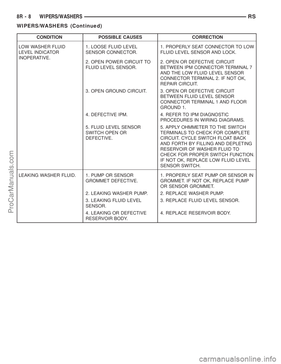
CONDITION POSSIBLE CAUSES CORRECTION
LOW WASHER FLUID
LEVEL INDICATOR
INOPERATIVE.1. LOOSE FLUID LEVEL
SENSOR CONNECTOR.1. PROPERLY SEAT CONNECTOR TO LOW
FLUID LEVEL SENSOR AND LOCK.
2. OPEN POWER CIRCUIT TO
FLUID LEVEL SENSOR.2. OPEN OR DEFECTIVE CIRCUIT
BETWEEN IPM CONNECTOR TERMINAL 7
AND THE LOW FLUID LEVEL SENSOR
CONNECTOR TERMINAL 2. IF NOT OK,
REPAIR CIRCUIT.
3. OPEN GROUND CIRCUIT. 3. OPEN OR DEFECTIVE CIRCUIT
BETWEEN FLUID LEVEL SENSOR
CONNECTOR TERMINAL 1 AND FLOOR
GROUND 1.
4. DEFECTIVE IPM. 4. REFER TO IPM DIAGNOSTIC
PROCEDURES IN WIRING DIAGRAMS.
5. FLUID LEVEL SENSOR
SWITCH OPEN OR
DEFECTIVE.5. APPLY OHMMETER TO THE SWITCH
TERMINALS TO CHECK FOR COMPLETE
CIRCUIT. CYCLE SWITCH FLOAT BACK
AND FORTH BY FILLING AND DEPLETING
RESERVOIR OF WASHER FLUID TO
CHECK FOR PROPER SWITCH FUNCTION.
IF NOT OK, REPLACE LOW FLUID LEVEL
SENSOR SWITCH.
LEAKING WASHER FLUID. 1. PUMP OR SENSOR
GROMMET DEFECTIVE.1. PROPERLY SEAT PUMP OR SENSOR IN
GROMMET. IF NOT OK, REPLACE PUMP
OR SENSOR GROMMET.
2. LEAKING WASHER PUMP. 2. REPLACE WASHER PUMP.
3. LEAKING FLUID LEVEL
SENSOR.3. REPLACE FLUID LEVEL SENSOR.
4. LEAKING OR DEFECTIVE
RESERVOIR BODY.4. REPLACE RESERVOIR BODY.
8R - 8 WIPERS/WASHERSRS
WIPERS/WASHERS (Continued)
ProCarManuals.com
Page 658 of 2399

WIRING
TABLE OF CONTENTS
page page
WIRING DIAGRAM INFORMATION....... 8W-01-1
COMPONENT INDEX.................. 8W-02-1
POWER DISTRIBUTION............... 8W-10-1
GROUND DISTRIBUTION.............. 8W-15-1
BUS COMMUNICATIONS.............. 8W-18-1
CHARGING SYSTEM.................. 8W-20-1
STARTING SYSTEM.................. 8W-21-1
FUEL/IGNITION SYSTEM.............. 8W-30-1
TRANSMISSION CONTROL SYSTEM..... 8W-31-1
VEHICLE SPEED CONTROL............ 8W-33-1
ANTILOCK BRAKES................... 8W-35-1
VEHICLE THEFT SECURITY SYSTEM..... 8W-39-1
INSTRUMENT CLUSTER............... 8W-40-1
HORN/CIGAR LIGHTER/POWER OUTLET . . 8W-41-1
AIR CONDITIONING-HEATER........... 8W-42-1
AIRBAG SYSTEM.................... 8W-43-1
INTERIOR LIGHTING.................. 8W-44-1
BODY CONTROL MODULE............. 8W-45-1MESSAGE CENTER................... 8W-46-1
AUDIO SYSTEM..................... 8W-47-1
REAR WINDOW DEFOGGER............ 8W-48-1
OVERHEAD CONSOLE................. 8W-49-1
FRONT LIGHTING.................... 8W-50-1
REAR LIGHTING..................... 8W-51-1
TURN SIGNALS...................... 8W-52-1
WIPERS............................ 8W-53-1
TRAILER TOW....................... 8W-54-1
POWER WINDOWS................... 8W-60-1
POWER DOOR LOCKS................ 8W-61-1
POWER MIRRORS................... 8W-62-1
POWER SEATS...................... 8W-63-1
SPLICE INFORMATION................ 8W-70-1
CONNECTOR PIN-OUTS............... 8W-80-1
CONNECTOR/GROUND/SPLICE
LOCATION........................ 8W-91-1
POWER DISTRIBUTION SYSTEM........ 8W-97-1 RSWIRING
8W-1
ProCarManuals.com
Page 660 of 2399

8W-01 WIRING DIAGRAM INFORMATION
TABLE OF CONTENTS
page page
WIRING DIAGRAM INFORMATION
DESCRIPTION
DESCRIPTION - HOW TO USE WIRING
DIAGRAMS...........................1
DESCRIPTION - CIRCUIT INFORMATION....5
DESCRIPTION - CIRCUIT FUNCTIONS......6
DESCRIPTION - SECTION IDENTIFICATION
AND INFORMATION....................6
DESCRIPTION - CONNECTOR, GROUND
AND SPLICE INFORMATION..............7
WARNING
WARNINGS - GENERAL.................7
DIAGNOSIS AND TESTING - WIRING
HARNESS............................7
STANDARD PROCEDURE
STANDARD PROCEDURE -
ELECTROSTATIC DISCHARGE (ESD)
SENSITIVE DEVICES...................8
STANDARD PROCEDURE - TESTING OF
VOLTAGE POTENTIAL...................9
STANDARD PROCEDURE - TESTING FOR
CONTINUITY..........................9STANDARD PROCEDURE - TESTING FOR A
SHORT TO GROUND...................9
STANDARD PROCEDURE - TESTING FOR A
SHORT TO GROUND ON FUSES
POWERING SEVERAL LOADS...........10
STANDARD PROCEDURE - TESTING FOR A
VOLTAGE DROP......................10
SPECIAL TOOLS
WIRING/TERMINAL....................10
CONNECTOR
REMOVAL.............................11
INSTALLATION.........................11
DIODE
REMOVAL.............................14
INSTALLATION.........................14
TERMINAL
REMOVAL.............................14
INSTALLATION.........................14
WIRE
STANDARD PROCEDURE - WIRE SPLICING . . 15
WIRING DIAGRAM
INFORMATION
DESCRIPTION
DESCRIPTION - HOW TO USE WIRING
DIAGRAMS
DaimlerChrysler Corporation wiring diagrams are
designed to provide information regarding the vehi-
cles wiring content. In order to effectively use the
wiring diagrams to diagnose and repair
DaimlerChrysler Corporation vehicles, it is important
to understand all of their features and characteris-
tics.
Diagrams are arranged such that the power (B+)
side of the circuit is placed near the top of the page,
and the ground (B-) side of the circuit is placed near
the bottom of the page (Fig. 1).
All switches, components, and modules are shown
in the at rest position with the doors closed and the
key removed from the ignition (Fig. 2).Components are shown two ways. A solid line
around a component indicates that the component is
complete. A dashed line around the component indi-
cates that the component is being shown is not com-
plete. Incomplete components have a reference
number to indicate the page where the component is
shown complete.
It is important to realize that no attempt is made
on the diagrams to represent components and wiring
as they appear on the vehicle. For example, a short
piece of wire is treated the same as a long one. In
addition, switches and other components are shown
as simply as possible, with regard to function only.
SYMBOLS
International symbols are used throughout the wir-
ing diagrams. These symbols are consistent with
those being used around the world (Fig. 3).
RS8W-01 WIRING DIAGRAM INFORMATION8W-01-1
ProCarManuals.com