bolt pattern CHRYSLER CARAVAN 2002 Service Manual
[x] Cancel search | Manufacturer: CHRYSLER, Model Year: 2002, Model line: CARAVAN, Model: CHRYSLER CARAVAN 2002Pages: 2399, PDF Size: 57.96 MB
Page 29 of 2399
INSTALLATION
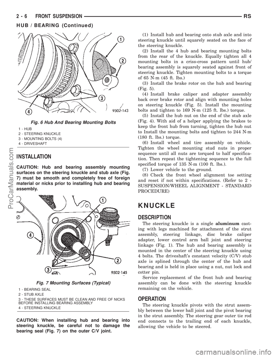
CAUTION: Hub and bearing assembly mounting
surfaces on the steering knuckle and stub axle (Fig.
7) must be smooth and completely free of foreign
material or nicks prior to installing hub and bearing
assembly.
CAUTION: When installing hub and bearing into
steering knuckle, be careful not to damage the
bearing seal (Fig. 7) on the outer C/V joint.(1) Install hub and bearing onto stub axle and into
steering knuckle until squarely seated on the face of
the steering knuckle.
(2) Install the 4 hub and bearing mounting bolts
from the rear of the knuckle. Equally tighten all 4
mounting bolts in a criss-cross pattern until hub/
bearing assembly is squarely seated against front of
steering knuckle. Tighten mounting bolts to a torque
of 65 N´m (45 ft. lbs.)
(3) Install the brake rotor on the hub and bearing
(Fig. 5).
(4) Install brake caliper and adapter assembly
back over brake rotor and align with mounting holes
on steering knuckle (Fig. 5). Install the mounting
bolts and tighten to 169 N´m (125 ft. lbs.) torque.
(5) Install the hub nut on the end of the stub axle
(Fig. 4). With aid of a helper applying the brakes to
keep the front hub from turning, tighten the hub nut
to Install the mounting bolts and tighten to 244 N´m
(180 ft. lbs.) torque.
(6) Install wheel and tire assembly on vehicle.
Tighten the wheel mounting stud nuts in proper
sequence until all nuts are torqued to half specifica-
tion. Then repeat the tightening sequence to the full
specified torque of 135 N´m (100 ft. lbs.).
(7) Lower vehicle to the ground.
(8) Check the front wheel alignment toe setting
and reset if not within specifications. (Refer to 2 -
SUSPENSION/WHEEL ALIGNMENT - STANDARD
PROCEDURE)
KNUCKLE
DESCRIPTION
The steering knuckle is a singlealuminumcast-
ing with legs machined for attachment of the strut
assembly, steering linkage, disc brake caliper
adapter, lower control arm ball joint and steering
linkage (Fig. 1). The hub and bearing assembly is
mounted in the center of the steering knuckle using
4 bolts. The driveshaft's constant velocity (C/V) stub
axle is splined through the center of the hub and
bearing and is held in place using a nut, nut lock and
cotter pin.
Service replacement of the front hub and bearing
assembly can be done with the steering knuckle
remaining on the vehicle.
OPERATION
The steering knuckle pivots with the strut assem-
bly between the lower ball joint and the pivot bearing
in the strut assembly. The steering gear outer tie rod
end connects to the trailing end of each knuckle,
allowing the vehicle to be steered.
Fig. 6 Hub And Bearing Mounting Bolts
1 - HUB
2 - STEERING KNUCKLE
3 - MOUNTING BOLTS (4)
4 - DRIVESHAFT
Fig. 7 Mounting Surfaces (Typical)
1 - BEARING SEAL
2 - STUB AXLE
3 - THESE SURFACES MUST BE CLEAN AND FREE OF NICKS
BEFORE INSTALLING BEARING ASSEMBLY
4 - STEERING KNUCKLE
2 - 6 FRONT SUSPENSIONRS
HUB / BEARING (Continued)
ProCarManuals.com
Page 56 of 2399
the outer joint of the driveshaft out of the hub/bear-
ing.
(15) Remove the hub/bearing to axle mounting
bolts (Fig. 13).
CAUTION: Corrosion may occur between the hub/
bearing and the axle. If this occurs the hub/bearing
will be difficult to remove from the axle. If the hub/
bearing will not come out of the axle by pulling on
it by hand, do not pound on the hub/bearing to
remove it from the axle. Pounding on the hub/bear-
ing to remove it from the axle will damage the hub/
bearing. This damage will result in noise or failure
of the hub/bearing. To remove a hub/bearing which
is corroded to the axle, lightly tap the disc brake
caliper adapter using a soft faced hammer. This will
remove both the disc brake caliper adapter and
hub/bearing from the axle. The hub/bearing will
then need to be removed from the caliper adapter.
(16) Remove the hub/bearing from the axle. (Fig.
12).
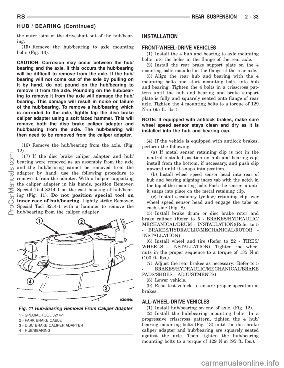
(17) If the disc brake caliper adapter and hub/
bearing were removed as an assembly from the axle
and the hub/bearing cannot be removed from the
adapter by hand, use the following procedure to
remove it from the adapter. With a helper supporting
the caliper adapter in his hands, position Remover,
Special Tool 8214-1 on the cast housing of hub/bear-
ing (Fig. 11).Do not position special tool on
inner race of hub/bearing.Lightly strike Remover,
Special Tool 8214-1 with a hammer to remove the
hub/bearing from the caliper adapter.INSTALLATION
FRONT-WHEEL-DRIVE VEHICLES
(1) Install the 4 hub and bearing to axle mounting
bolts into the holes in the flange of the rear axle.
(2)
Install the rear brake support plate on the 4
mounting bolts installed in the flange of the rear axle.
(3) Align the rear hub and bearing with the 4
mounting bolts and start mounting bolts into hub
and bearing. Tighten the 4 bolts in a crisscross pat-
tern until the hub and bearing and brake support
plate is fully and squarely seated onto flange of rear
axle. Tighten the 4 mounting bolts to a torque of 129
N´m (95 ft. lbs.)
NOTE: If equipped with antilock brakes, make sure
wheel speed sensor stays clean and dry as it is
installed into the hub and bearing cap.
(4) If the vehicle is equipped with antilock brakes,
perform the following:
(a) If metal sensor retaining clip is not in the
neutral installed position on hub and bearing cap,
install from the bottom, if necessary, and push clip
upward until it snaps into position.
(b)
Install wheel speed sensor head into rear of
hub and bearing aligning index tab with the notch in
the top of the mounting hole. Push the sensor in until
it snaps into place on the metal retaining clip.
(c) Install secondary (yellow) retaining clip over
wheel speed sensor head and engage the tabs on
each side (Fig. 8).
(5) Install brake drum or disc brake rotor and
brake caliper. (Refer to 5 - BRAKES/HYDRAULIC/
MECHANICAL/DRUM - INSTALLATION)(Refer to 5
- BRAKES/HYDRAULIC/MECHANICAL/ROTOR -
INSTALLATION)
(6) Install wheel and tire (Refer to 22 - TIRES/
WHEELS - INSTALLATION). Tighten the wheel
nuts in the proper sequence to a torque of 135 N´m
(100 ft. lbs.).
(7) Adjust the rear brakes as necessary. (Refer to 5
- BRAKES/HYDRAULIC/MECHANICAL/BRAKE
PADS/SHOES - ADJUSTMENTS)
(8) Lower vehicle.
(9) Road test vehicle to ensure proper operation of
brakes.
ALL-WHEEL-DRIVE VEHICLES
(1) Install hub/bearing on end of axle. (Fig. 12).
(2) Install the hub/bearing mounting bolts. In a
progressive crisscross pattern, tighten the 4 hub/
bearing mounting bolts (Fig. 13) until the disc brake
caliper adapter and hub/bearing are squarely seated
against the axle. Then tighten the hub/bearing
mounting bolts to a torque of 129 N´m (95 ft. lbs.).Fig. 11 Hub/Bearing Removal From Caliper Adapter
1 - SPECIAL TOOL 8214-1
2 - PARK BRAKE CABLE
3 - DISC BRAKE CALIPER ADAPTER
4 - HUB/BEARING
RSREAR SUSPENSION2-33
HUB / BEARING (Continued)
ProCarManuals.com
Page 211 of 2399
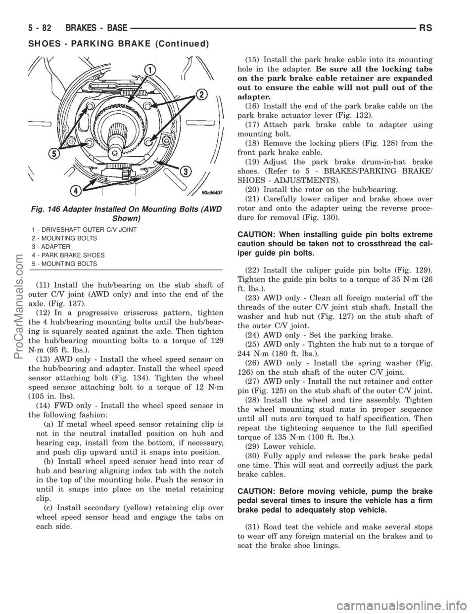
(11) Install the hub/bearing on the stub shaft of
outer C/V joint (AWD only) and into the end of the
axle. (Fig. 137).
(12) In a progressive crisscross pattern, tighten
the 4 hub/bearing mounting bolts until the hub/bear-
ing is squarely seated against the axle. Then tighten
the hub/bearing mounting bolts to a torque of 129
N´m (95 ft. lbs.).
(13) AWD only - Install the wheel speed sensor on
the hub/bearing and adapter. Install the wheel speed
sensor attaching bolt (Fig. 134). Tighten the wheel
speed sensor attaching bolt to a torque of 12 N´m
(105 in. lbs).
(14) FWD only - Install the wheel speed sensor in
the following fashion:
(a) If metal wheel speed sensor retaining clip is
not in the neutral installed position on hub and
bearing cap, install from the bottom, if necessary,
and push clip upward until it snaps into position.
(b) Install wheel speed sensor head into rear of
hub and bearing aligning index tab with the notch
in the top of the mounting hole. Push the sensor in
until it snaps into place on the metal retaining
clip.
(c) Install secondary (yellow) retaining clip over
wheel speed sensor head and engage the tabs on
each side.(15) Install the park brake cable into its mounting
hole in the adapter.Be sure all the locking tabs
on the park brake cable retainer are expanded
out to ensure the cable will not pull out of the
adapter.
(16) Install the end of the park brake cable on the
park brake actuator lever (Fig. 132).
(17) Attach park brake cable to adapter using
mounting bolt.
(18) Remove the locking pliers (Fig. 128) from the
front park brake cable.
(19) Adjust the park brake drum-in-hat brake
shoes. (Refer to 5 - BRAKES/PARKING BRAKE/
SHOES - ADJUSTMENTS).
(20) Install the rotor on the hub/bearing.
(21) Carefully lower caliper and brake shoes over
rotor and onto the adapter using the reverse proce-
dure for removal (Fig. 130).
CAUTION: When installing guide pin bolts extreme
caution should be taken not to crossthread the cal-
iper guide pin bolts.
(22) Install the caliper guide pin bolts (Fig. 129).
Tighten the guide pin bolts to a torque of 35 N´m (26
ft. lbs.).
(23) AWD only - Clean all foreign material off the
threads of the outer C/V joint stub shaft. Install the
washer and hub nut (Fig. 127) on the stub shaft of
the outer C/V joint.
(24) AWD only - Set the parking brake.
(25) AWD only - Tighten the hub nut to a torque of
244 N´m (180 ft. lbs.).
(26) AWD only - Install the spring washer (Fig.
126) on the stub shaft of the outer C/V joint.
(27) AWD only - Install the nut retainer and cotter
pin (Fig. 125) on the stub shaft of the outer C/V joint.
(28) Install the wheel and tire assembly. Tighten
the wheel mounting stud nuts in proper sequence
until all nuts are torqued to half specification. Then
repeat the tightening sequence to the full specified
torque of 135 N´m (100 ft. lbs.).
(29) Lower vehicle.
(30) Fully apply and release the park brake pedal
one time. This will seat and correctly adjust the park
brake cables.
CAUTION: Before moving vehicle, pump the brake
pedal several times to insure the vehicle has a firm
brake pedal to adequately stop vehicle.
(31) Road test the vehicle and make several stops
to wear off any foreign material on the brakes and to
seat the brake shoe linings.
Fig. 146 Adapter Installed On Mounting Bolts (AWD
Shown)
1 - DRIVESHAFT OUTER C/V JOINT
2 - MOUNTING BOLTS
3 - ADAPTER
4 - PARK BRAKE SHOES
5 - MOUNTING BOLTS
5 - 82 BRAKES - BASERS
SHOES - PARKING BRAKE (Continued)
ProCarManuals.com
Page 260 of 2399
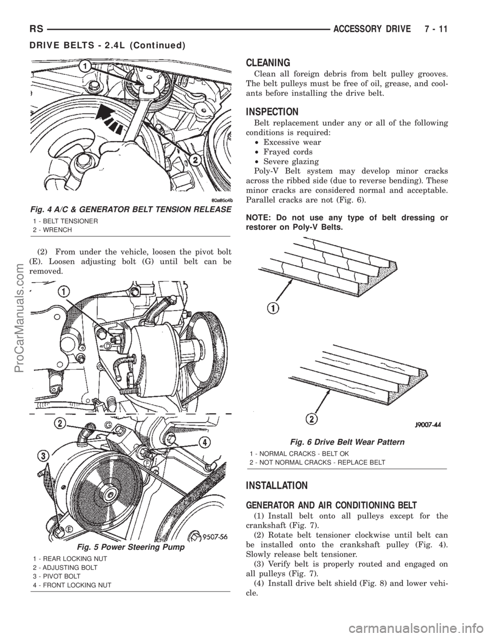
(2) From under the vehicle, loosen the pivot bolt
(E). Loosen adjusting bolt (G) until belt can be
removed.
CLEANING
Clean all foreign debris from belt pulley grooves.
The belt pulleys must be free of oil, grease, and cool-
ants before installing the drive belt.
INSPECTION
Belt replacement under any or all of the following
conditions is required:
²Excessive wear
²Frayed cords
²Severe glazing
Poly-V Belt system may develop minor cracks
across the ribbed side (due to reverse bending). These
minor cracks are considered normal and acceptable.
Parallel cracks are not (Fig. 6).
NOTE: Do not use any type of belt dressing or
restorer on Poly-V Belts.
INSTALLATION
GENERATOR AND AIR CONDITIONING BELT
(1) Install belt onto all pulleys except for the
crankshaft (Fig. 7).
(2) Rotate belt tensioner clockwise until belt can
be installed onto the crankshaft pulley (Fig. 4).
Slowly release belt tensioner.
(3) Verify belt is properly routed and engaged on
all pulleys (Fig. 7).
(4) Install drive belt shield (Fig. 8) and lower vehi-
cle.
Fig. 4 A/C & GENERATOR BELT TENSION RELEASE
1 - BELT TENSIONER
2 - WRENCH
Fig. 5 Power Steering Pump
1 - REAR LOCKING NUT
2 - ADJUSTING BOLT
3 - PIVOT BOLT
4 - FRONT LOCKING NUT
Fig. 6 Drive Belt Wear Pattern
1 - NORMAL CRACKS - BELT OK
2 - NOT NORMAL CRACKS - REPLACE BELT
RSACCESSORY DRIVE7-11
DRIVE BELTS - 2.4L (Continued)
ProCarManuals.com
Page 479 of 2399
OPERATION
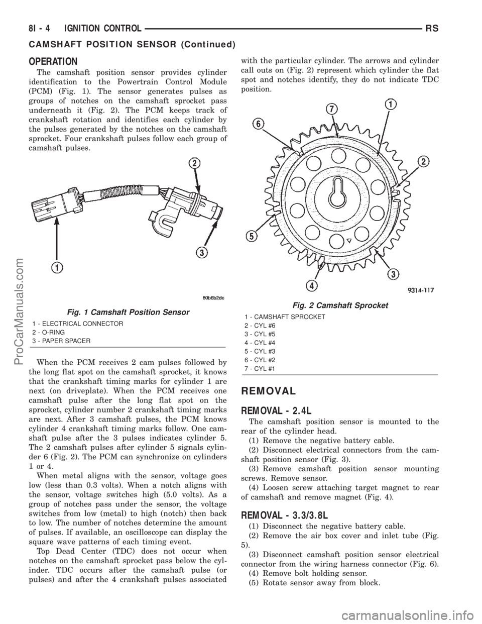
The camshaft position sensor provides cylinder
identification to the Powertrain Control Module
(PCM) (Fig. 1). The sensor generates pulses as
groups of notches on the camshaft sprocket pass
underneath it (Fig. 2). The PCM keeps track of
crankshaft rotation and identifies each cylinder by
the pulses generated by the notches on the camshaft
sprocket. Four crankshaft pulses follow each group of
camshaft pulses.
When the PCM receives 2 cam pulses followed by
the long flat spot on the camshaft sprocket, it knows
that the crankshaft timing marks for cylinder 1 are
next (on driveplate). When the PCM receives one
camshaft pulse after the long flat spot on the
sprocket, cylinder number 2 crankshaft timing marks
are next. After 3 camshaft pulses, the PCM knows
cylinder 4 crankshaft timing marks follow. One cam-
shaft pulse after the 3 pulses indicates cylinder 5.
The 2 camshaft pulses after cylinder 5 signals cylin-
der 6 (Fig. 2). The PCM can synchronize on cylinders
1or4.
When metal aligns with the sensor, voltage goes
low (less than 0.3 volts). When a notch aligns with
the sensor, voltage switches high (5.0 volts). As a
group of notches pass under the sensor, the voltage
switches from low (metal) to high (notch) then back
to low. The number of notches determine the amount
of pulses. If available, an oscilloscope can display the
square wave patterns of each timing event.
Top Dead Center (TDC) does not occur when
notches on the camshaft sprocket pass below the cyl-
inder. TDC occurs after the camshaft pulse (or
pulses) and after the 4 crankshaft pulses associatedwith the particular cylinder. The arrows and cylinder
call outs on (Fig. 2) represent which cylinder the flat
spot and notches identify, they do not indicate TDC
position.
REMOVAL
REMOVAL - 2.4L
The camshaft position sensor is mounted to the
rear of the cylinder head.
(1) Remove the negative battery cable.
(2) Disconnect electrical connectors from the cam-
shaft position sensor (Fig. 3).
(3) Remove camshaft position sensor mounting
screws. Remove sensor.
(4) Loosen screw attaching target magnet to rear
of camshaft and remove magnet (Fig. 4).
REMOVAL - 3.3/3.8L
(1) Disconnect the negative battery cable.
(2) Remove the air box cover and inlet tube (Fig.
5).
(3) Disconnect camshaft position sensor electrical
connector from the wiring harness connector (Fig. 6).
(4) Remove bolt holding sensor.
(5) Rotate sensor away from block.
Fig. 1 Camshaft Position Sensor
1 - ELECTRICAL CONNECTOR
2 - O-RING
3 - PAPER SPACER
Fig. 2 Camshaft Sprocket
1 - CAMSHAFT SPROCKET
2 - CYL #6
3 - CYL #5
4 - CYL #4
5 - CYL #3
6 - CYL #2
7 - CYL #1
8I - 4 IGNITION CONTROLRS
CAMSHAFT POSITION SENSOR (Continued)
ProCarManuals.com
Page 1238 of 2399
CAUTION: Ensure all abrasives are removed from
engine parts after honing. It is recommended that a
solution of soap and hot water be used with a
brush and the parts then thoroughly dried. The bore
can be considered clean when it can be wiped
clean with a white cloth and cloth remains clean.
Oil the bores after cleaning to prevent rusting.
CLEANING
Clean cylinder block thoroughly using a suitable
cleaning solvent.
INSPECTION
ENGINE BLOCK
(1) Clean cylinder block thoroughly and check all
core hole plugs for evidence of leaking.
(2) If new core plugs are to be installed, (Refer to 9
- ENGINE - STANDARD PROCEDURE - ENGINE
CORE AND OIL GALLERY PLUGS).
(3) Examine block and cylinder bores for cracks or
fractures.
(4) Check block deck surfaces for flatness. Deck
surface must be within service limit of 0.1 mm (0.004
in.).
CYLINDER BORE
NOTE: The cylinder bores should be measured at
normal room temperature, 21ÉC (70ÉF).The cylinder walls should be checked for out-of-
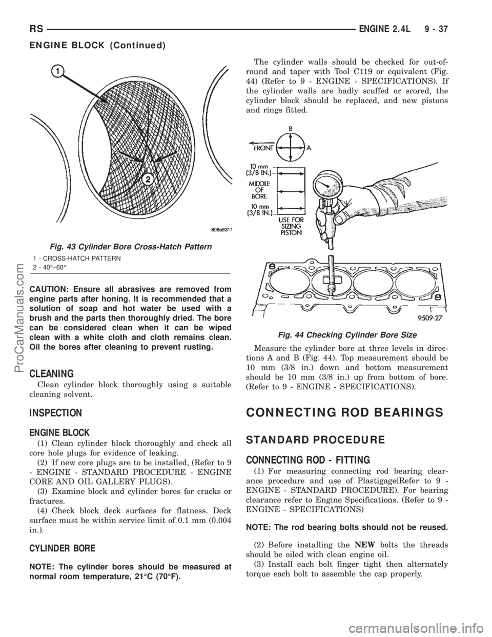
round and taper with Tool C119 or equivalent (Fig.
44) (Refer to 9 - ENGINE - SPECIFICATIONS). If
the cylinder walls are badly scuffed or scored, the
cylinder block should be replaced, and new pistons
and rings fitted.
Measure the cylinder bore at three levels in direc-
tions A and B (Fig. 44). Top measurement should be
10 mm (3/8 in.) down and bottom measurement
should be 10 mm (3/8 in.) up from bottom of bore.
(Refer to 9 - ENGINE - SPECIFICATIONS).
CONNECTING ROD BEARINGS
STANDARD PROCEDURE
CONNECTING ROD - FITTING
(1) For measuring connecting rod bearing clear-
ance procedure and use of Plastigage(Refer to 9 -
ENGINE - STANDARD PROCEDURE). For bearing
clearance refer to Engine Specifications. (Refer to 9 -
ENGINE - SPECIFICATIONS)
NOTE: The rod bearing bolts should not be reused.
(2) Before installing theNEWbolts the threads
should be oiled with clean engine oil.
(3) Install each bolt finger tight then alternately
torque each bolt to assemble the cap properly.
Fig. 43 Cylinder Bore Cross-Hatch Pattern
1 - CROSS-HATCH PATTERN
2 - 40ɱ60É
Fig. 44 Checking Cylinder Bore Size
RSENGINE 2.4L9-37
ENGINE BLOCK (Continued)
ProCarManuals.com