change wheel CHRYSLER CARAVAN 2002 Service Manual
[x] Cancel search | Manufacturer: CHRYSLER, Model Year: 2002, Model line: CARAVAN, Model: CHRYSLER CARAVAN 2002Pages: 2399, PDF Size: 57.96 MB
Page 28 of 2399
DIAGNOSIS AND TESTING - HUB AND
BEARING
The condition of the front hub and bearing assem-
bly is diagnosed using the inspection and testing pro-
cedure detailed below.
The bearing contained in the Unit III front hub/
bearing assembly will produce noise and vibration
when worn or damaged. The noise will generally
change when the bearings are loaded. A road test of
the vehicle is normally required to determine the
location of a worn or damaged bearing.
Find a smooth level road surface and bring the
vehicle up to a constant speed. When vehicle is at a
constant speed, swerve the vehicle back and forth
from the left and to the right. This will load and
unload the bearings and change the noise level.
When bearing damage is slight, the noise is some-
times noticeable at lower speeds and at other times
is more noticeable at speeds above 105 km/h (65
mph).
REMOVAL
NOTE: Replacement of the Unit III front hub/bearing
assembly can be normally done without having to
remove the steering knuckle from the vehicle. In the
event that the hub/bearing is frozen in the steering
knuckle and cannot be removed by hand, it will
have to be pressed out of the steering knuckle. The
steering knuckle will require removal from the vehi-
cle to allow the hub/bearing assembly to be
pressed out of the steering knuckle. (Refer to 2 -
SUSPENSION/FRONT/KNUCKLE - REMOVAL)
(1) Raise vehicle. (Refer to LUBRICATION &
MAINTENANCE/HOISTING - STANDARD PROCE-
DURE)
(2) Remove wheel lug nuts, and front tire and
wheel assembly.
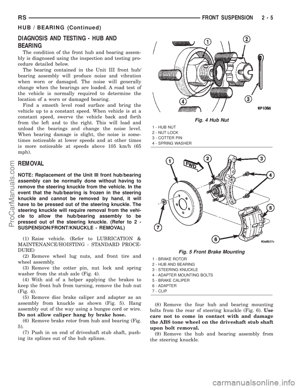
(3) Remove the cotter pin, nut lock and spring
washer from the stub axle (Fig. 4).
(4) With aid of a helper applying the brakes to
keep the front hub from turning, remove the hub nut
(Fig. 4).
(5) Remove disc brake caliper and adapter as an
assembly from knuckle as shown (Fig. 5). Hang
assembly out of the way using a bungee cord or wire.
Do not allow caliper hang by brake hose.
(6) Remove brake rotor from hub and bearing (Fig.
5).
(7) Push in on end of driveshaft stub shaft, push-
ing its splines out of the hub splines.(8) Remove the four hub and bearing mounting
bolts from the rear of steering knuckle (Fig. 6).Use
care not to come in contact with and damage
the ABS tone wheel on the driveshaft stub shaft
upon bolt removal.
(9) Remove the hub and bearing assembly from
the steering knuckle.
Fig. 4 Hub Nut
1 - HUB NUT
2 - NUT LOCK
3 - COTTER PIN
4 - SPRING WASHER
Fig. 5 Front Brake Mounting
1 - BRAKE ROTOR
2 - HUB AND BEARING
3 - STEERING KNUCKLE
4 - ADAPTER MOUNTING BOLTS
5 - BRAKE CALIPER
6 - ADAPTER
7 - CLIP
RSFRONT SUSPENSION2-5
HUB / BEARING (Continued)
ProCarManuals.com
Page 48 of 2399
(12) Slowly release the tension from the coil spring
by backing off the compressor drive fully. As the ten-
sion is relieved, make sure the upper mount, pivot
bearing and upper seat are align properly. Remove
the clamp from the lower end of the coil spring and
strut. Push back the spring compressor upper and
lower hooks, then remove the strut assembly from
the spring compressor.
(13) Install strut assembly on the vehicle. (Refer to
2 - SUSPENSION/FRONT/STRUT - INSTALLA-
TION)
INSTALLATION - STRUT ASSEMBLY
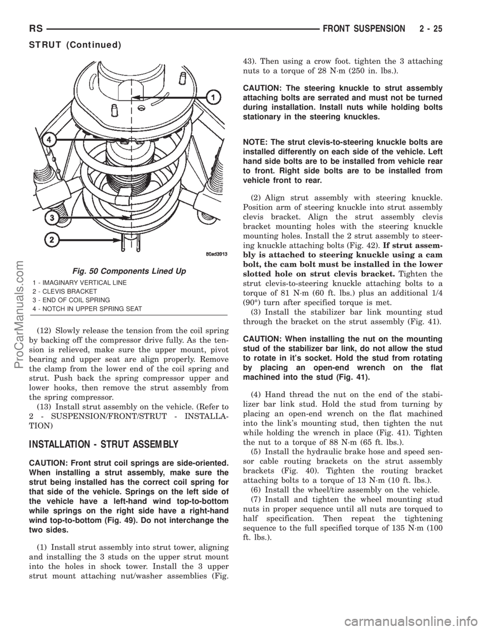
CAUTION: Front strut coil springs are side-oriented.
When installing a strut assembly, make sure the
strut being installed has the correct coil spring for
that side of the vehicle. Springs on the left side of
the vehicle have a left-hand wind top-to-bottom
while springs on the right side have a right-hand
wind top-to-bottom (Fig. 49). Do not interchange the
two sides.
(1) Install strut assembly into strut tower, aligning
and installing the 3 studs on the upper strut mount
into the holes in shock tower. Install the 3 upper
strut mount attaching nut/washer assemblies (Fig.43). Then using a crow foot. tighten the 3 attaching
nuts to a torque of 28 N´m (250 in. lbs.).
CAUTION: The steering knuckle to strut assembly
attaching bolts are serrated and must not be turned
during installation. Install nuts while holding bolts
stationary in the steering knuckles.
NOTE: The strut clevis-to-steering knuckle bolts are
installed differently on each side of the vehicle. Left
hand side bolts are to be installed from vehicle rear
to front. Right side bolts are to be installed from
vehicle front to rear.
(2) Align strut assembly with steering knuckle.
Position arm of steering knuckle into strut assembly
clevis bracket. Align the strut assembly clevis
bracket mounting holes with the steering knuckle
mounting holes. Install the 2 strut assembly to steer-
ing knuckle attaching bolts (Fig. 42).If strut assem-
bly is attached to steering knuckle using a cam
bolt, the cam bolt must be installed in the lower
slotted hole on strut clevis bracket.Tighten the
strut clevis-to-steering knuckle attaching bolts to a
torque of 81 N´m (60 ft. lbs.) plus an additional 1/4
(90É) turn after specified torque is met.
(3) Install the stabilizer bar link mounting stud
through the bracket on the strut assembly (Fig. 41).
CAUTION: When installing the nut on the mounting
stud of the stabilizer bar link, do not allow the stud
to rotate in it's socket. Hold the stud from rotating
by placing an open-end wrench on the flat
machined into the stud (Fig. 41).
(4) Hand thread the nut on the end of the stabi-
lizer bar link stud. Hold the stud from turning by
placing an open-end wrench on the flat machined
into the link's mounting stud, then tighten the nut
while holding the wrench in place (Fig. 41). Tighten
the nut to a torque of 88 N´m (65 ft. lbs.).
(5) Install the hydraulic brake hose and speed sen-
sor cable routing brackets on the strut assembly
brackets (Fig. 40). Tighten the routing bracket
attaching bolts to a torque of 13 N´m (10 ft. lbs.).
(6) Install the wheel/tire assembly on the vehicle.
(7) Install and tighten the wheel mounting stud
nuts in proper sequence until all nuts are torqued to
half specification. Then repeat the tightening
sequence to the full specified torque of 135 N´m (100
ft. lbs.).
Fig. 50 Components Lined Up
1 - IMAGINARY VERTICAL LINE
2 - CLEVIS BRACKET
3 - END OF COIL SPRING
4 - NOTCH IN UPPER SPRING SEAT
RSFRONT SUSPENSION2-25
STRUT (Continued)
ProCarManuals.com
Page 54 of 2399
OPERATION
The hub and bearing has internal bearings that
allow the hub to rotate with the tire and wheel
assembly (and driveshaft on All-Wheel-Drive vehi-
cles). The five wheel mounting studs mount the tire
and wheel assembly, and disc brake rotor or brake
drum to the vehicle.
On All-Wheel-Drive vehicles, the splined mating of
the driveshaft stub axle and hub allows the drive-
shaft to rotate with the hub and wheel.
Front-Wheel-Drive vehicles equipped with antilock
brakes have a wheel speed sensor and tone wheel
mounted to the rear of the hub and bearing. The tone
wheel rotates with the hub which is sensed by the
wheel speed sensor.
DIAGNOSIS AND TESTING - HUB AND
BEARING
The bearing contained in the hub and bearing
assembly will produce noise and vibration when worn
or damaged. The noise will generally change when
the bearings are loaded. A road test of the vehicle is
normally required to determine the location of a
worn or damaged bearing.
Find a smooth level road surface and bring the
vehicle up to a constant speed. When vehicle is at a
constant speed, swerve the vehicle back and forth
from the left and to the right. This will load and
unload the bearings and change the noise level.
When bearing damage is slight, the noise is some-
times noticeable at lower speeds and at other times
is more noticeable at speeds above 105 km/h (65
mph).
REMOVAL
FRONT-WHEEL-DRIVE VEHICLES
(1) Raise vehicle. (Refer to LUBRICATION &
MAINTENANCE/HOISTING - STANDARD PROCE-
DURE)
(2) Remove wheel and tire. (Refer to 22 - TIRES/
WHEELS - REMOVAL)
(3) Remove brake drum or disc brake caliper and
rotor from hub and bearing. (Refer to 5 - BRAKES/
HYDRAULIC/MECHANICAL/DRUM - REMOVAL-
)(Refer to 5 - BRAKES/HYDRAULIC/MECHANICAL/
ROTOR - REMOVAL)
(4) If equipped with antilock brakes, perform the
following:
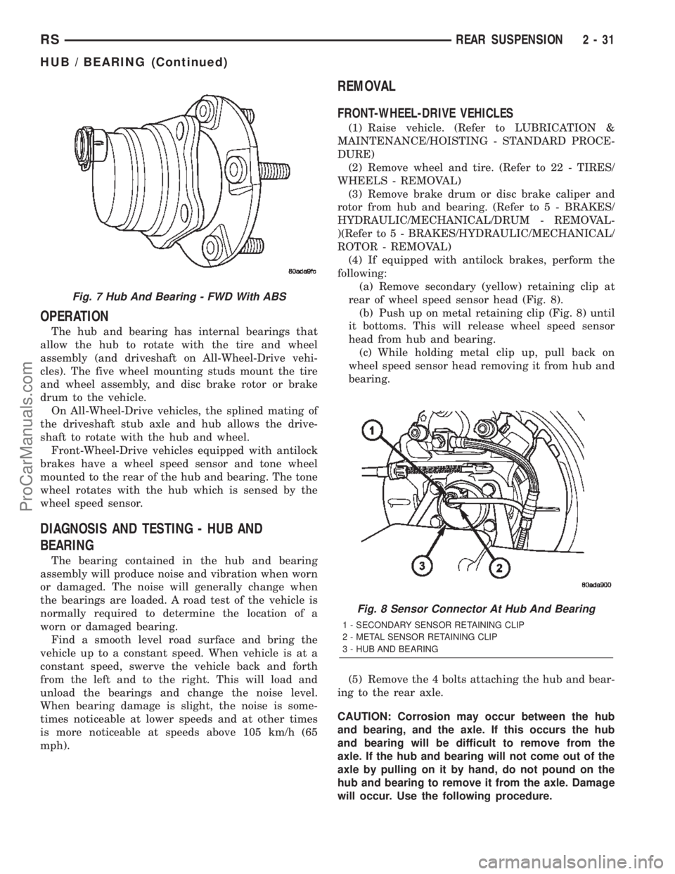
(a) Remove secondary (yellow) retaining clip at
rear of wheel speed sensor head (Fig. 8).
(b) Push up on metal retaining clip (Fig. 8) until
it bottoms. This will release wheel speed sensor
head from hub and bearing.
(c) While holding metal clip up, pull back on
wheel speed sensor head removing it from hub and
bearing.
(5) Remove the 4 bolts attaching the hub and bear-
ing to the rear axle.
CAUTION: Corrosion may occur between the hub
and bearing, and the axle. If this occurs the hub
and bearing will be difficult to remove from the
axle. If the hub and bearing will not come out of the
axle by pulling on it by hand, do not pound on the
hub and bearing to remove it from the axle. Damage
will occur. Use the following procedure.
Fig. 7 Hub And Bearing - FWD With ABS
Fig. 8 Sensor Connector At Hub And Bearing
1 - SECONDARY SENSOR RETAINING CLIP
2 - METAL SENSOR RETAINING CLIP
3 - HUB AND BEARING
RSREAR SUSPENSION2-31
HUB / BEARING (Continued)
ProCarManuals.com
Page 74 of 2399
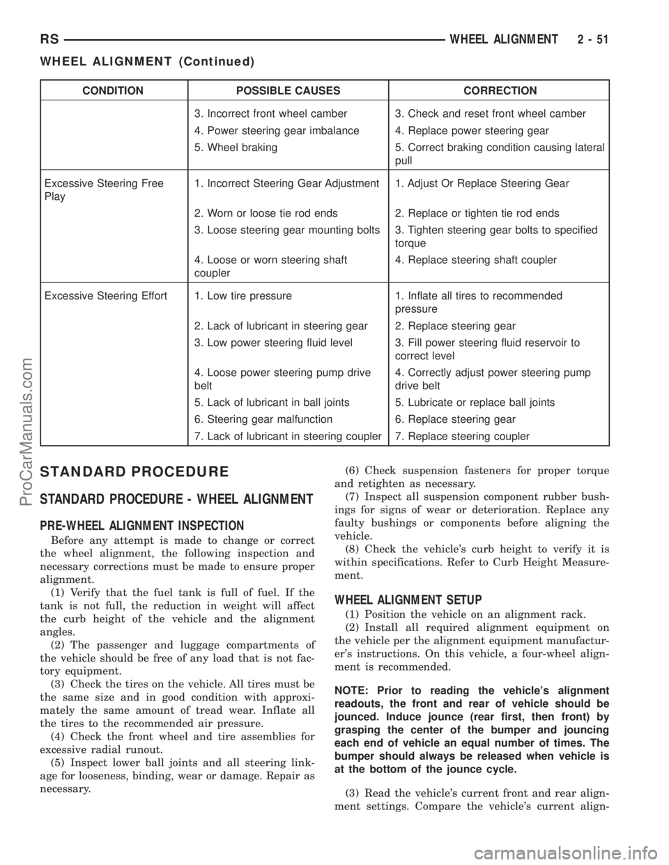
CONDITION POSSIBLE CAUSES CORRECTION
3. Incorrect front wheel camber 3. Check and reset front wheel camber
4. Power steering gear imbalance 4. Replace power steering gear
5. Wheel braking 5. Correct braking condition causing lateral
pull
Excessive Steering Free
Play1. Incorrect Steering Gear Adjustment 1. Adjust Or Replace Steering Gear
2. Worn or loose tie rod ends 2. Replace or tighten tie rod ends
3. Loose steering gear mounting bolts 3. Tighten steering gear bolts to specified
torque
4. Loose or worn steering shaft
coupler4. Replace steering shaft coupler
Excessive Steering Effort 1. Low tire pressure 1. Inflate all tires to recommended
pressure
2. Lack of lubricant in steering gear 2. Replace steering gear
3. Low power steering fluid level 3. Fill power steering fluid reservoir to
correct level
4. Loose power steering pump drive
belt4. Correctly adjust power steering pump
drive belt
5. Lack of lubricant in ball joints 5. Lubricate or replace ball joints
6. Steering gear malfunction 6. Replace steering gear
7. Lack of lubricant in steering coupler 7. Replace steering coupler
STANDARD PROCEDURE
STANDARD PROCEDURE - WHEEL ALIGNMENT
PRE-WHEEL ALIGNMENT INSPECTION
Before any attempt is made to change or correct
the wheel alignment, the following inspection and
necessary corrections must be made to ensure proper
alignment.
(1) Verify that the fuel tank is full of fuel. If the
tank is not full, the reduction in weight will affect
the curb height of the vehicle and the alignment
angles.
(2) The passenger and luggage compartments of
the vehicle should be free of any load that is not fac-
tory equipment.
(3) Check the tires on the vehicle. All tires must be
the same size and in good condition with approxi-
mately the same amount of tread wear. Inflate all
the tires to the recommended air pressure.
(4) Check the front wheel and tire assemblies for
excessive radial runout.
(5) Inspect lower ball joints and all steering link-
age for looseness, binding, wear or damage. Repair as
necessary.(6) Check suspension fasteners for proper torque
and retighten as necessary.
(7) Inspect all suspension component rubber bush-
ings for signs of wear or deterioration. Replace any
faulty bushings or components before aligning the
vehicle.
(8) Check the vehicle's curb height to verify it is
within specifications. Refer to Curb Height Measure-
ment.
WHEEL ALIGNMENT SETUP
(1) Position the vehicle on an alignment rack.
(2) Install all required alignment equipment on
the vehicle per the alignment equipment manufactur-
er's instructions. On this vehicle, a four-wheel align-
ment is recommended.
NOTE: Prior to reading the vehicle's alignment
readouts, the front and rear of vehicle should be
jounced. Induce jounce (rear first, then front) by
grasping the center of the bumper and jouncing
each end of vehicle an equal number of times. The
bumper should always be released when vehicle is
at the bottom of the jounce cycle.
(3) Read the vehicle's current front and rear align-
ment settings. Compare the vehicle's current align-
RSWHEEL ALIGNMENT2-51
WHEEL ALIGNMENT (Continued)
ProCarManuals.com
Page 80 of 2399
DIFFERENTIAL & DRIVELINE
TABLE OF CONTENTS
page page
HALF SHAFT - FRONT.....................1
HALF SHAFT - REAR.....................14PROPELLER SHAFT.....................22
REAR DRIVELINE MODULE................24
HALF SHAFT - FRONT
TABLE OF CONTENTS
page page
HALF SHAFT - FRONT
DESCRIPTION..........................1
DIAGNOSIS AND TESTING - HALF SHAFT.....1
REMOVAL.............................2
INSTALLATION..........................4
SPECIFICATIONS - HALF SHAFT - FRONT....6
CV BOOT - INNER
REMOVAL.............................6INSTALLATION..........................6
CV BOOT - OUTER
REMOVAL.............................10
INSTALLATION.........................10
OUTER CV JOINT BEARING SHIELD
REMOVAL.............................13
INSTALLATION.........................13
HALF SHAFT - FRONT
DESCRIPTION
All vehicles use an unequal length half shaft sys-
tem (Fig. 1).
The left half shaft uses a tuned rubber damper
weight. When replacing the left half shaft, be sure
the replacement half shaft has the same damper
weight as the original.
All half shaft assemblies use the same type of
inner and outer joints. The inner joint of both half
shaft assemblies is a tripod joint, and the outer joint
of both half shaft assemblies is a Rzeppa joint. Both
tripod joints and Rzeppa joints are true constant
velocity (CV) joint assemblies. The inner tripod joint
allows for the changes in half shaft length through
the jounce and rebound travel of the front suspen-
sion.
On vehicles equipped with ABS brakes, the outer
CV joint is equipped with a tone wheel used to deter-
mine vehicle speed for ABS brake operation.
The inner tripod joint of both half shafts is splined
into the transaxle side gears. The inner tripod joints
are retained in the side gears of the transaxle using
a snap ring located in the stub shaft of the tripod
joint. The outer CV joint has a stub shaft that issplined into the wheel hub and retained by a steel
hub nut.DIAGNOSIS AND TESTING - HALF SHAFT
VEHICLE INSPECTION
(1) Check for grease in the vicinity of the inboard
tripod joint and outboard CV joint; this is a sign of
inner or outer joint seal boot or seal boot clamp dam-
age.
NOISE AND/OR VIBRATION IN TURNS
A clicking noise and/or a vibration in turns could
be caused by one of the following conditions:
²Damaged outer CV or inner tripod joint seal
boot or seal boot clamps. This will result in the loss
and/or contamination of the joint grease, resulting in
inadequate lubrication of the joint.
²Noise may also be caused by another component
of the vehicle coming in contact with the half shafts.
CLUNKING NOISE DURING ACCELERATION
This noise may be a result of one of the following
conditions:
²A torn seal boot on the inner or outer joint of the
half shaft assembly.
RSDIFFERENTIAL & DRIVELINE3-1
ProCarManuals.com
Page 93 of 2399
HALF SHAFT - REAR
TABLE OF CONTENTS
page page
HALF SHAFT - REAR
DESCRIPTION.........................14
DIAGNOSIS AND TESTING - HALF SHAFT....14
REMOVAL.............................15
INSTALLATION.........................15SPECIFICATIONS - HALF SHAFT - FRONT . . . 16
CV BOOT - INNER/OUTER
REMOVAL.............................17
INSTALLATION.........................18
HALF SHAFT - REAR
DESCRIPTION
The inner and outer joints of both half shaft
assemblies are tripod joints. The tripod joints are
true constant velocity (CV) joint assemblies, which
allow for the changes in half shaft length through
the jounce and rebound travel of the rear suspension.
On vehicles equipped with ABS brakes, the outer
CV joint is equipped with a tone wheel used to deter-
mine vehicle speed for ABS brake operation.
The inner tripod joint of both half shafts is bolted
rear differential assembly's output flanges. The outer
CV joint has a stub shaft that is splined into the
wheel hub and retained by a steel hub nut.
DIAGNOSIS AND TESTING - HALF SHAFT
VEHICLE INSPECTION
(1) Check for grease in the vicinity of the inboard
tripod joint and outboard CV joint; this is a sign of
inner or outer joint seal boot or seal boot clamp dam-
age.
NOISE AND/OR VIBRATION IN TURNS
A clicking noise and/or a vibration in turns could
be caused by one of the following conditions:
²Damaged outer CV or inner tripod joint seal
boot or seal boot clamps. This will result in the loss
and/or contamination of the joint grease, resulting in
inadequate lubrication of the joint.²Noise may also be caused by another component
of the vehicle coming in contact with the half shafts.
CLUNKING NOISE DURING ACCELERATION
This noise may be a result of one of the following
conditions:
²A torn seal boot on the inner or outer joint of the
half shaft assembly.
²A loose or missing clamp on the inner or outer
joint of the half shaft assembly.
²A damaged or worn half shaft CV joint.
SHUDDER OR VIBRATION DURING ACCELERATION
This problem could be a result of:
²A worn or damaged half shaft inner tripod joint.
²A sticking tripod joint spider assembly (inner tri-
pod joint only).
²Improper wheel alignment. (Refer to 2 - SUS-
PENSION/WHEEL ALIGNMENT - STANDARD
PROCEDURE)
VIBRATION AT HIGHWAY SPEEDS
This problem could be a result of:
²Foreign material (mud, etc.) packed on the back-
side of the wheel(s).
²Out of balance tires or wheels. (Refer to 22 -
TIRES/WHEELS - STANDARD PROCEDURE)
²Improper tire and/or wheel runout. (Refer to 22 -
TIRES/WHEELS - DIAGNOSIS AND TESTING)
3 - 14 HALF SHAFT - REARRS
ProCarManuals.com
Page 103 of 2399
REAR DRIVELINE MODULE
TABLE OF CONTENTS
page page
REAR DRIVELINE MODULE
DESCRIPTION.........................24
OPERATION...........................24
DIAGNOSIS AND TESTING
DIAGNOSIS AND TESTING - REAR
DRIVELINE MODULE NOISE.............25
DIAGNOSIS AND TESTING - REAR
DRIVELINE MODULE OPERATION........27
REMOVAL.............................27
DISASSEMBLY.........................28
ASSEMBLY............................30
INSTALLATION.........................34
SPECIFICATIONS - REAR DRIVELINE
MODULE............................35
SPECIAL TOOLS.......................35
BI-DIRECTIONAL OVERRUNNING CLUTCH
DESCRIPTION.........................36
OPERATION...........................38
DIFFERENTIAL ASSEMBLY
DESCRIPTION.........................41OPERATION...........................41
FLUID - DIFFERENTIAL ASSEMBLY
STANDARD PROCEDURE - DIFFERENTIAL
ASSEMBLY FLUID DRAIN AND FILL.......42
FLUID
STANDARD PROCEDURE - OVERRUNNING
CLUTCH HOUSING FLUID CHANGE.......43
VISCOUS COUPLER
DESCRIPTION.........................44
OPERATION...........................44
TORQUE ARM
REMOVAL.............................46
INSTALLATION.........................46
INPUT FLANGE SEAL
REMOVAL.............................46
INSTALLATION.........................47
OUTPUT FLANGE SEAL
REMOVAL.............................48
INSTALLATION.........................49
REAR DRIVELINE MODULE
DESCRIPTION
The rear driveline module assembly (Fig. 1) con-
sists of four main components:
²Bi-Directional Overrunning Clutch (BOC)
²Viscous Coupling
²Differential Assembly
²Torque Arm
The viscous coupling and bi-directional overrun-
ning clutch are contained within an overrunning
clutch housing, which fastens to the differential
assembly. The overrunning clutch housing and differ-
ential assembly have unique fluid sumps, each
requiring their own type and capacity of fluid. The
overrunning clutch housing requires MopartATF+4
(Automatic Transmission FluidÐType 9602) or equiv-
alent. The differential assembly requires
Driveline module service is limited to the following
components:
²Differential Assembly (serviced only as assem-
bly)
²Viscous Coupling
²Bi-Directional Overrunning Clutch (BOC)
²Overrunning Clutch Housing
²Seals (Input Flange, Output Flange, Overrun-
ning Clutch Housing O-rings)²Input Flange/Shield
²Torque Arm
²Vents
²Fasteners
OPERATION
The primary benefits of All Wheel Drive are:
²Superior straight line acceleration, and corner-
ing on all surfaces
²Better traction and handling under adverse con-
ditions, resulting in improved hill climbing ability
and safer driving.
The heart of the system is an inter-axle viscous
coupling. The vehicle retains predominantly front-
wheel drive characteristics, but the All Wheel Drive
capability takes effect when the front wheels start to
slip. Under normal level road, straight line driving,
100% of the torque is allocated to the front wheels.
The viscous coupling controls and distributes torque/
power to the rear wheels. The viscous coupling trans-
mits torque to the rear wheels in proportion of the
amount of the slippage at the front wheels. Thais
variable torque distribution is automatic with no
driver inputs required. The coupling is similar to a
multi-plate clutch. It consists of a series of closely
spaced discs, which are alternately connected to the
front and rear drive units. The unit is totally sealed
and partially filled with silicone fluid. There is no
3 - 24 REAR DRIVELINE MODULERS
ProCarManuals.com
Page 105 of 2399
²Wheel bearings
²Engine
²Transmission
²Exhaust
²Propeller shaft (vibration)
²Vehicle body (drumming)
Driveline module noises are normally divided into
two categories: gear noise or bearing noise. A thor-
ough and careful inspection should be completed to
determine the actual source of the noise before
replacing the driveline module.
The rubber mounting bushings help to dampen-out
driveline module noise when properly installed.
Inspect to confirm that no metal contact exists
between the driveline module case and the body. The
complete isolation of noise to one area requires
expertise and experience. Identifying certain types of
vehicle noise baffles even the most capable techni-
cians. Often such practices as:
²Increase tire inflation pressure to eliminate tire
noise.
²Listen for noise at varying speeds with different
driveline load conditions
²Swerving the vehicle from left to right to detect
wheel bearing noise.
All driveline module assemblies produce noise to a
certain extent. Slight carrier noise that is noticeable
only at certain speeds or isolated situations should be
considered normal. Carrier noise tends to peak at a
variety of vehicle speeds. Noise isNOT ALWAYSan
indication of a problem within the carrier.
TIRE NOISE
Tire noise is often mistaken for driveline module
noise. Tires that are unbalanced, worn unevenly or
are worn in a saw-tooth manner are usually noisy.
They often produce a noise that appears to originate
in the driveline module.
Tire noise changes with different road surfaces, but
driveline module noise does not. Inflate all four tires
with approximately 20 psi (138 kPa) more than the
recommended inflation pressure (for test purposes
only). This will alter noise caused by tires, but will
not affect noise caused by the differential. Rear axle
noise usually ceases when coasting at speeds less
than 30 mph (48 km/h); however, tire noise contin-
ues, but at a lower frequency, as the speed is
reduced.
After test has been completed lower tire pressure
back to recommended pressure.
GEAR NOISE (DRIVE PINION AND RING GEAR)
Abnormal gear noise is rare and is usually caused
by scoring on the ring gear and drive pinion. Scoring
is the result of insufficient or incorrect lubricant in
the carrier housing.Abnormal gear noise can be easily recognized. It
produces a cycling tone that will be very pronounced
within a given speed range. The noise can occur dur-
ing one or more of the following drive conditions:
²Drive
²Road load
²Float
²Coast
Abnormal gear noise usually tends to peak within
a narrow vehicle speed range or ranges. It is usually
more pronounced between 30 to 40 mph (48 to 64
km/h) and 50 to 60 mph (80 to 96 km/h). When objec-
tionable gear noise occurs, note the driving condi-
tions and the speed range.
BEARING NOISE (DRIVE PINION AND
DIFFERENTIAL)
Defective bearings produce a rough growl that is
constant in pitch and varies with the speed of vehi-
cle. Being aware of this will enable a technician to
separate bearing noise from gear noise.
Drive pinion bearing noise that results from defec-
tive or damaged bearings can usually be identified by
its constant, rough sound. Drive pinion front bearing
is usually more pronounced during a coast condition.
Drive pinion rear bearing noise is more pronounced
during a drive condition. The drive pinion bearings
are rotating at a higher rate of speed than either the
differential side bearings or the axle shaft bearing.
Differential side bearing noise will usually produce
a constant, rough sound. The sound is much lower in
frequency than the noise caused by drive pinion bear-
ings.
Bearing noise can best be detected by road testing
the vehicle on a smooth road (black top). However, it
is easy to mistake tire noise for bearing noise. If a
doubt exists, the tire treads should be examined for
irregularities that often causes a noise that resem-
bles bearing noise.
ENGINE AND TRANSMISSION NOISE
Sometimes noise that appears to be in the driv-
eline module assembly is actually caused by the
engine or the transmission. To identify the true
source of the noise, note the approximate vehicle
speed and/or RPM when the noise is most noticeable.
Stop the vehicle next to a flat brick or cement wall
(this will help reflect the sound). Place the transaxle
inNEUTRAL. Accelerate the engine slowly up
through the engine speed that matches the vehicle
speed noted when the noise occurred. If the same
noise is produced, it usually indicates that the noise
is being caused by the engine or transaxle.
3 - 26 REAR DRIVELINE MODULERS
REAR DRIVELINE MODULE (Continued)
ProCarManuals.com
Page 117 of 2399
OPERATION
In order to achieve all-wheel drive operation in
reverse, the overrunning clutch locking functional direc-
tion must be reversible. The bi-directional overrunning
clutch (BOC) changes the operational mode direction
depending on the propeller shaft direction. The propel-
ler shaft rotates in the clockwise (when viewed from the
front) direction when the vehicle is moving forward,
which indexes the BOC to the forward overrunning
position. When the vehicle is in reverse, the propeller
shaft will rotate counter-clockwise and index the BOC
to the reverse overrunning position.
The BOC acts as a mechanical stator. It is active
(transmitting torque), or it is not active and in over-
running mode (not transmitting torque). This ªall or
nothingº approach to torque transfer would cause a
sudden application of all available power to the rear
wheels, which is not desirable. Therefore it is run in
series with a viscous coupler to smooth, dampen, and
limit the transmission of torque to the rear axle and
to prevent a step style torque input to the rear axle.
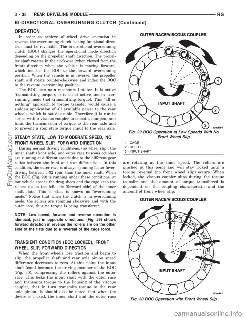
STEADY STATE, LOW TO MODERATE SPEED, NO
FRONT WHEEL SLIP, FORWARD DIRECTION
During normal driving conditions, (no wheel slip), the
inner shaft (front axle) and outer race (viscous coupler)
are running at different speeds due to the different gear
ratios between the front and rear differentials. In this
condition, the outer race is always spinning faster (over-
driving between 5-32 rpm) than the inner shaft. When
the BOC (Fig. 29) is running under these conditions, at
low vehicle speeds the drag shoes and the cage keep the
rollers up on the left side (forward side) of the inner
shaft flats. This is what is known as ªoverrunning
mode.º Notice that when the clutch is in overrunning
mode, the rollers are spinning clockwise and with the
outer race, thus no torque is being transferred.
NOTE: Low speed, forward and reverse operation is
identical, just in opposite directions. (Fig. 29) shows
forward direction in reverse the rollers are on the other
side of the flats due to a reversal of the cage force.
TRANSIENT CONDITION (BOC LOCKED), FRONT
WHEEL SLIP, FORWARD DIRECTION
When the front wheels lose traction and begin to
slip, the propeller shaft and rear axle pinion speed
difference decreases to zero. At this point the input
shaft (cam) becomes the driving member of the BOC
(Fig. 30), compressing the rollers against the outer
race. This locks the input shaft with the outer race
and transmits torque to the housing of the viscous
coupler, that in turn transmits torque to the rear
axle pinion. It should also be noted that when the
device is locked, the inner shaft and the outer raceare rotating at the same speed. The rollers are
pinched at this point and will stay locked until a
torque reversal (no front wheel slip) occurs. When
locked, the viscous coupler slips during the torque
transfer and the amount of torque transferred is
dependent on the coupling characteristic and the
amount of front wheel slip.
Fig. 29 BOC Operation at Low Speeds With No
Front Wheel Slip
1 - CAGE
2 - ROLLER
3 - INPUT SHAFT
Fig. 30 BOC Operation with Front Wheel Slip
3 - 38 REAR DRIVELINE MODULERS
BI-DIRECTIONAL OVERRUNNING CLUTCH (Continued)
ProCarManuals.com
Page 144 of 2399
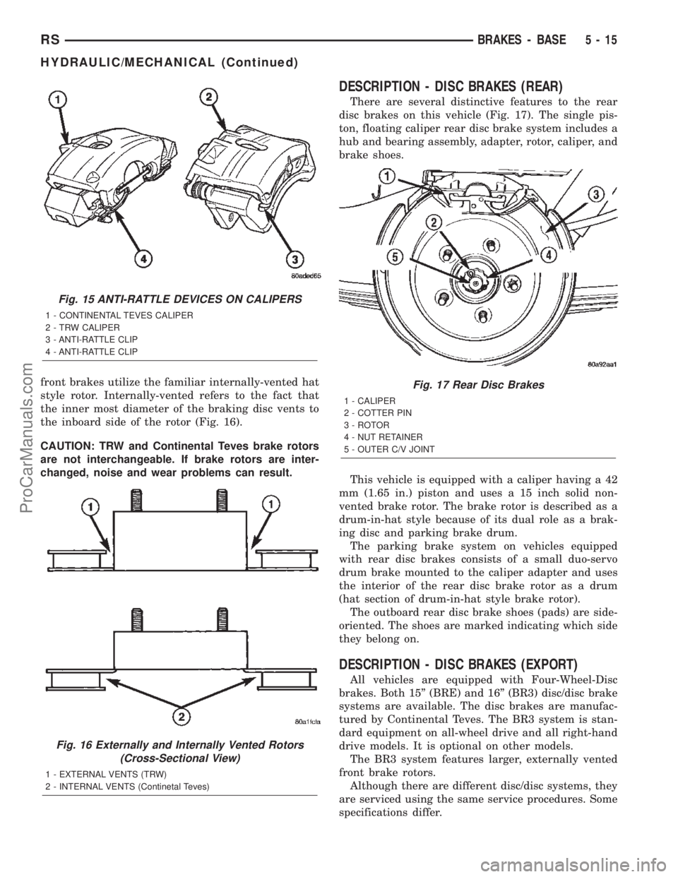
front brakes utilize the familiar internally-vented hat
style rotor. Internally-vented refers to the fact that
the inner most diameter of the braking disc vents to
the inboard side of the rotor (Fig. 16).
CAUTION: TRW and Continental Teves brake rotors
are not interchangeable. If brake rotors are inter-
changed, noise and wear problems can result.
DESCRIPTION - DISC BRAKES (REAR)
There are several distinctive features to the rear
disc brakes on this vehicle (Fig. 17). The single pis-
ton, floating caliper rear disc brake system includes a
hub and bearing assembly, adapter, rotor, caliper, and
brake shoes.
This vehicle is equipped with a caliper having a 42
mm (1.65 in.) piston and uses a 15 inch solid non-
vented brake rotor. The brake rotor is described as a
drum-in-hat style because of its dual role as a brak-
ing disc and parking brake drum.
The parking brake system on vehicles equipped
with rear disc brakes consists of a small duo-servo
drum brake mounted to the caliper adapter and uses
the interior of the rear disc brake rotor as a drum
(hat section of drum-in-hat style brake rotor).
The outboard rear disc brake shoes (pads) are side-
oriented. The shoes are marked indicating which side
they belong on.
DESCRIPTION - DISC BRAKES (EXPORT)
All vehicles are equipped with Four-Wheel-Disc
brakes. Both 15º (BRE) and 16º (BR3) disc/disc brake
systems are available. The disc brakes are manufac-
tured by Continental Teves. The BR3 system is stan-
dard equipment on all-wheel drive and all right-hand
drive models. It is optional on other models.
The BR3 system features larger, externally vented
front brake rotors.
Although there are different disc/disc systems, they
are serviced using the same service procedures. Some
specifications differ.
Fig. 15 ANTI-RATTLE DEVICES ON CALIPERS
1 - CONTINENTAL TEVES CALIPER
2 - TRW CALIPER
3 - ANTI-RATTLE CLIP
4 - ANTI-RATTLE CLIP
Fig. 16 Externally and Internally Vented Rotors
(Cross-Sectional View)
1 - EXTERNAL VENTS (TRW)
2 - INTERNAL VENTS (Continetal Teves)
Fig. 17 Rear Disc Brakes
1 - CALIPER
2 - COTTER PIN
3 - ROTOR
4 - NUT RETAINER
5 - OUTER C/V JOINT
RSBRAKES - BASE5-15
HYDRAULIC/MECHANICAL (Continued)
ProCarManuals.com