change wheel CHRYSLER CARAVAN 2002 User Guide
[x] Cancel search | Manufacturer: CHRYSLER, Model Year: 2002, Model line: CARAVAN, Model: CHRYSLER CARAVAN 2002Pages: 2399, PDF Size: 57.96 MB
Page 146 of 2399
BRAKE LINES
DESCRIPTION - BRAKE TUBES AND HOSES
The brake tubes are steel with a corrosion-resis-
tant nylon coating applied to the external surfaces.
The flex hoses are made of reinforced rubber with fit-
tings at each end.
The primary and secondary brake tubes leading
from the master cylinder to the ABS ICU Hydraulic
Control Unit (HCU) or the non-ABS junction block
have a special flexible section. This flexible section is
required due to cradle movement while the vehicle is
in motion (The ICU and non-ABS junction block are
mounted to the cradle).If replacement of these
lines is necessary, only the original factory
brake line containing the flexible section must
be used.
OPERATION - BRAKE TUBES AND HOSES
The purpose of the chassis brake tubes and flex
hoses is to transfer the pressurized brake fluid devel-
oped by the master cylinder to the wheel brakes of
the vehicle. The flex hoses are made of rubber to
allow for the movement of the vehicle's suspension.
INSPECTION - BRAKE TUBES AND HOSES
Flexible rubber hose is used at both front brakes
and at the rear axle. Inspection of brake hoses
should be performed whenever the brake system is
serviced and every 7,500 miles or 12 months, which-
ever comes first (every engine oil change). Inspect
hydraulic brake hoses for surface cracking, scuffing,
or worn spots. If the fabric casing of the rubber hose
becomes exposed due to cracks or abrasions in the
rubber hose cover, the hose should be replaced imme-
diately. Eventual deterioration of the hose can take
place with possible burst failure. Faulty installation
can cause twisting, resulting in wheel, tire, or chassis
interference.
The brake tubing should be inspected periodically
for evidence of physical damage or contact with mov-
ing or hot components.
The flexible brake tube sections used on this vehi-
cle in the primary and secondary tubes from the
master cylinder to the ABS hydraulic control unit
connections must also be inspected. This flexible tub-
ing must be inspected for kinks, fraying and contact
with other components or with the body of the vehi-
cle.
BRAKE PADS/SHOES - FRONT
REMOVAL
REMOVAL - FRONT DISC BRAKE SHOES
(DISC/DISC BRAKES)
(1) Raise the vehicle. (Refer to LUBRICATION &
MAINTENANCE/HOISTING - STANDARD PROCE-
DURE).
(2) Remove both front wheel and tire assemblies.
(3) Begin on one side of the vehicle.
(4) Remove the anti-rattle clip from the outboard
side of the caliper and adapter.
(5) Remove the two caliper guide pin bolts.
(6) Remove caliper from caliper adapter and brake
rotor.
CAUTION: Supporting weight of caliper by the flex-
ible brake fluid hose can damage the hose.
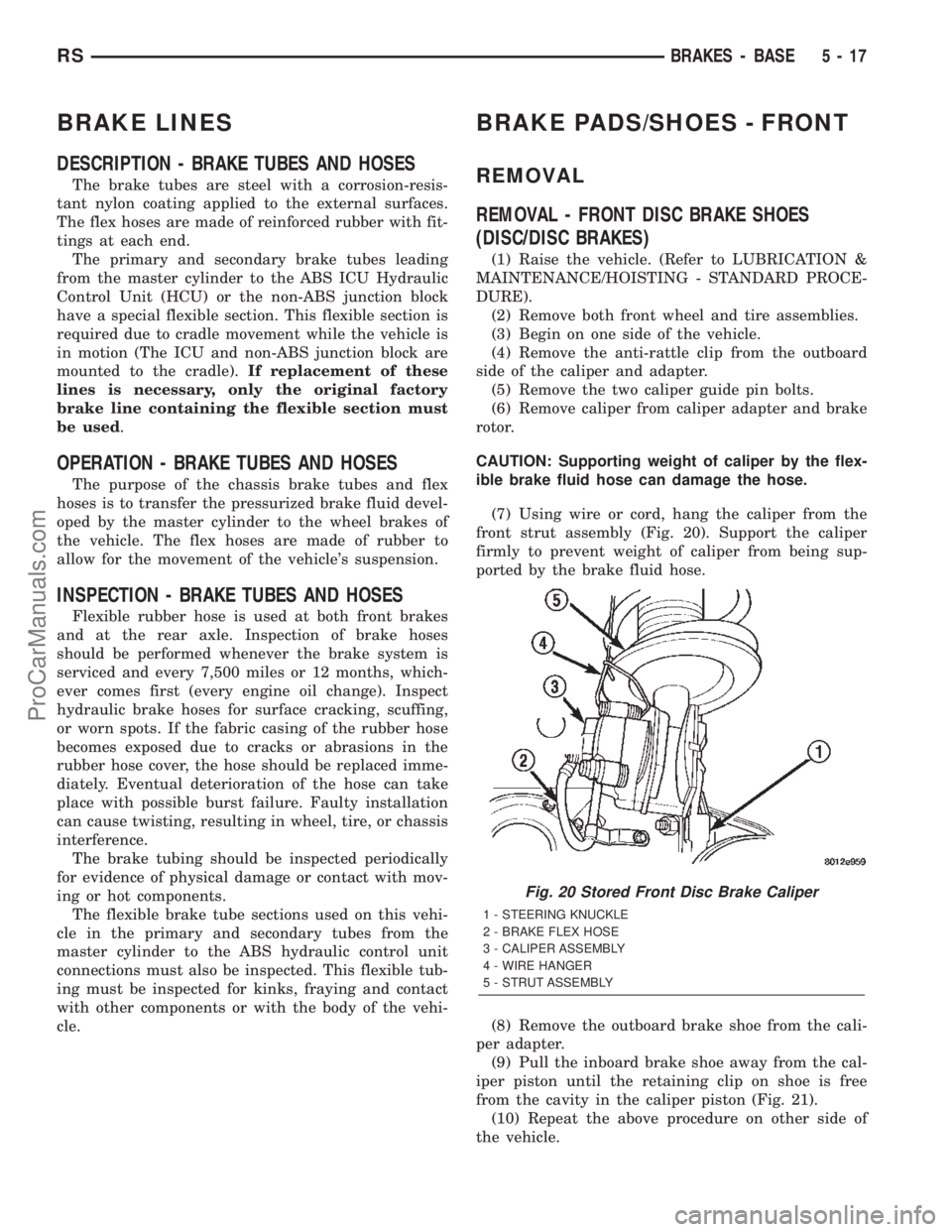
(7) Using wire or cord, hang the caliper from the
front strut assembly (Fig. 20). Support the caliper
firmly to prevent weight of caliper from being sup-
ported by the brake fluid hose.
(8) Remove the outboard brake shoe from the cali-
per adapter.
(9) Pull the inboard brake shoe away from the cal-
iper piston until the retaining clip on shoe is free
from the cavity in the caliper piston (Fig. 21).
(10) Repeat the above procedure on other side of
the vehicle.
Fig. 20 Stored Front Disc Brake Caliper
1 - STEERING KNUCKLE
2 - BRAKE FLEX HOSE
3 - CALIPER ASSEMBLY
4 - WIRE HANGER
5 - STRUT ASSEMBLY
RSBRAKES - BASE5-17
ProCarManuals.com
Page 159 of 2399
should be taken not to cross thread the caliper
guide pin bolts.
(4) Install the anti-rattle clip on the outboard side
of the caliper. Start the clip into the holes on the cal-
iper, then stretch the clip legs past the abutments on
the caliper adapter.
CAUTION: When connecting the brake hose to the
caliper, install new brake hose to caliper special
copper washers.
(5) Install the brake hose on the caliper. To do
this, first place one NEW special fitting washer on
each side of the hose fitting, then slide the banjo bolt
through the fitting. Next, thread the banjo bolt into
the threaded port on the rear of the brake caliper.
Tighten the banjo bolt to a torque of 47 N´m (35 ft.
lbs.).
(6) Install the wheel and tire assembly. Tighten
the wheel mounting stud nuts in proper sequence
until all nuts are torqued to half specification, then
repeat the tightening sequence to the full specified
torque of 135 N´m (100 ft. lbs.).
(7) Lower the vehicle.
(8) Remove the brake pedal depressor (holding)
tool.
(9) Bleed the hydraulic brake circuit to the brake
caliper. (Refer to 5 - BRAKES - STANDARD PROCE-
DURE)
(10) Road test the vehicle and make several stops
to wear off any foreign material on the brakes and to
seat the brake shoe linings.
INSTALLATION - FRONT DISC BRAKE CALIPER
(DISC/DRUM BRAKES)
CAUTION: TRW and Continental Teves brake cali-
pers are not interchangeable. Each caliper is specif-
ically designed for the unique brake system (TRW -
disc/drum brake combination and Continental Teves
- disc/disc brake combination). If calipers are inter-
changed, improper performance, noise and
increased stopping distance can occur.
(1) Completely retract the caliper piston back into
the bore of the caliper. Use a C-clamp to retract the
piston if necessary. Place a wood block over the pis-
ton before installing the C-clamp to avoid damaging
the piston.
CAUTION: Use care when installing the caliper onto
the disc brake adapter to avoid damaging the boots
on the caliper guide pins.
(2) Install the disc brake caliper over the brake
shoes on the brake caliper adapter.(3) Align the caliper guide pin bolt holes with the
guide pins. Install the caliper guide pin bolts and
tighten them to a torque of 35 N´m (26 ft. lbs.) (Fig.
40).
(4) Install the banjo bolt connecting the brake hose
to the brake caliper (Fig. 40). Install NEW copper
washers on each side of the hose fitting as the banjo
bolt is guided through the fitting. Thread the banjo
bolt into the caliper and tighten it to a torque of 47
N´m (35 ft. lbs.).
(5) Install the tire and wheel assembly. Tighten
the wheel mounting nuts to a torque of 135 N´m (100
ft. lbs.).
(6) Lower the vehicle.
(7) Remove the brake pedal holding tool.
(8) Bleed the caliper as necessary. (Refer to 5 -
BRAKES - BASE - STANDARD PROCEDURE).
(9) Road test the vehicle and make several stops to
wear off any foreign material on the brakes and to
seat the brake shoes.
DISC BRAKE CALIPER - REAR
REMOVAL - REAR DISC BRAKE CALIPER
NOTE: Handling of the rotor and caliper, must be
done in such a way as to avoid damage to the rotor
and scratching or nicking of lining on the brake
shoes.
(1) Depress the brake pedal past its first inch of
travel and hold it in this position using a brake pedal
depressor (holding) tool. This is done to isolate the
master cylinder from the brake hydraulic system dis-
allowing the brake fluid to completely drain out of
the brake fluid reservoir.
(2) Raise the vehicle. (Refer to LUBRICATION &
MAINTENANCE/HOISTING - STANDARD PROCE-
DURE)
(3) Remove rear wheel and tire assembly from
vehicle.
(4) Remove the banjo bolt connecting the brake
hose to the brake caliper. There are two washers (one
on each side of the brake hose fitting) that will come
off with the banjo bolt. Discard these washers.
(5) Remove the disc brake caliper to adapter guide
pin bolts (Fig. 45).
(6) Remove rear caliper from adapter using the fol-
lowing procedure. First rotate front of caliper up
from the adapter. Then pull the rear of the caliper
and the outboard brake shoe anti-rattle clip out from
under the rear abutment on the adapter (Fig. 46).
(7) If the brake rotor requires removal, it can now
be removed by first removing the retainer clips from
the wheel mounting studs, then pulling the rotor
straight off the studs.
5 - 30 BRAKES - BASERS
DISC BRAKE CALIPER - FRONT (Continued)
ProCarManuals.com
Page 171 of 2399
(5) Install wiring harness connector to brake fluid
level switch mounted in brake fluid reservoir (Fig.
57).
(6) Install battery, clamp and nut.
(7) Install battery shield.
(8) Connect positive battery terminal.
(9) Connect negative battery terminal.
(10) Fill master cylinder with clean, fresh Mopart
Brake Fluid or equivalent.
(11) Road test vehicle to ensure proper operation of
brakes.
INSTALLATION - RHD
CAUTION: Different types of master cylinders are
used on this vehicle depending on brake options. If
a new master cylinder is being installed, be sure it
is the correct master cylinder for the type of brake
system the vehicle is equipped with.
CAUTION: When replacing the master cylinder on a
vehicle, a NEW vacuum seal MUST be installed on
the master cylinder.
(1) Install a NEW vacuum seal on master cylinder
making sure seal fits squarely in groove of master
cylinder casting.
(2) Position master cylinder on studs of power
brake booster, aligning booster push rod with master
cylinder piston.
(3) Install the two master cylinder mounting nuts
(Fig. 59). Tighten both mounting nuts to a torque of
25 N´m (225 in. lbs.).
CAUTION: When tightening the primary and sec-
ondary brake tube nuts at master cylinder, be sure
brake tubes do not contact any other components
within the vehicle and that there is slack in the flex-
ible sections of the tubes. This is required due to
the movement between the ABS ICU and the master
cylinder while the vehicle is in motion.
(4) Connect primary and secondary brake tubes to
master cylinder primary and secondary ports (Fig.
59). Brake tubes must be held securely when tight-
ened to control orientation of flex section. Tighten
tube nuts to a torque of 17 N´m (145 in. lbs.).
(5) Install wiring harness connector to brake fluid
level switch mounted in brake fluid reservoir (Fig.
55).
(6) Install battery, clamp and nut.
(7) Install battery shield.
(8) Connect positive battery terminal.
(9) Connect negative battery terminal.
(10) Fill master cylinder with clean, fresh Mopart
Brake Fluid or equivalent.(11) Road test vehicle to ensure proper operation of
brakes.
PEDAL - ADJUSTABLE
DESCRIPTION
The Adjustable Pedals System (APS) is designed to
enable the fore and aft repositioning of the brake and
accelerator pedals. This results in improved ergonom-
ics in relation to the steering wheel for taller and
shorter drivers. Being able to adjust the pedal posi-
tions also allows the driver to set steering wheel tilt
and seat position to the most comfortable position.
The effort required for pedal application will not
change regardless of pedal position.
The adjustable pedal system allows the pedals to
adjust up to 3 inches (75 mm) at a rate of approxi-
mately 0.4 in./sec. (9 mm/sec.). An adjustment switch
is located on the left side of the steering column
lower shroud.
If the vehicle is equipped with Remote Keyless
Entry (RKE), an optional memory feature is avail-
able.
The serviceable components of the APS are:
²Adjustable pedal assembly (includes motor,
cables, pedals, gear box, sensor and module)
²Adjustable pedal module (Refer to 8 - ELECTRI-
CAL/ELECTRONIC CONTROL MODULES/
ADJUSTABLE PEDAL MODULE)
²Adjustable pedal switch
²Pedal position sensor
OPERATION
Change of pedal position is accomplished by means
of a motor driven screw. Operating the adjustable
pedal switch activates the pedal drive motor. The
pedal drive motor turns a screw that changes the
position of the accelerator pedal. The motor also
drives a cable connected to a gear box that changes
the brake pedal position the same distance as the
accelerator pedal. The pedals can be moved rearward
(closer to the driver) or forward (away from driver).
Each pedal is moved on its activating lever to a posi-
tion where the driver feels most comfortable. The
position and operation of the activating levers are not
changed.
Pedal adjustment is inhibited when the vehicle is
in reverse or when cruise control is engaged. The
Electronic Vehicle Information Center (EVIC) will
display a message when the Adjustable Pedal Module
(APM) is disabled. i.e.:9Adjustable Pedal Disabled -
Cruise Control Engaged9or9Adjustable Pedal Dis-
abled - Vehicle in Reverse9.
Foot pressure or debris can stall pedal adjustment.
In order to avoid damage to system components dur-
5 - 42 BRAKES - BASERS
MASTER CYLINDER (Continued)
ProCarManuals.com
Page 172 of 2399
ing pedal adjustment, the APM will monitor pedal
position sensor voltage. If the APM does not detect
expected voltage change within 3 seconds, it will cut
power to the adjustable pedal motor.
An optional memory feature is available. This
allows storing of one or two preferred pedal positions
in the APS. A preferred position can be stored and
recalled using the door-mounted switches. A stored
pedal position can be recalled (but not stored) using
the Remote Keyless Entry (RKE) if equipped with
the memory feature.
DIAGNOSIS AND TESTING - ADJUSTABLE
PEDAL SYSTEM
Refer to Appropriate Diagnostic Information.
REMOVAL
NOTE: Before proceeding, review all Steering Col-
umn and Airbag Warnings and Cautions. (Refer to
19 - STEERING/COLUMN - WARNING)(Refer to 8 -
ELECTRICAL/RESTRAINTS - WARNING)
(1) Remove battery ground cable terminal from
battery negative post and isolate.
(2) Under instrument panel, remove silencer panel
below lower steering column cover.
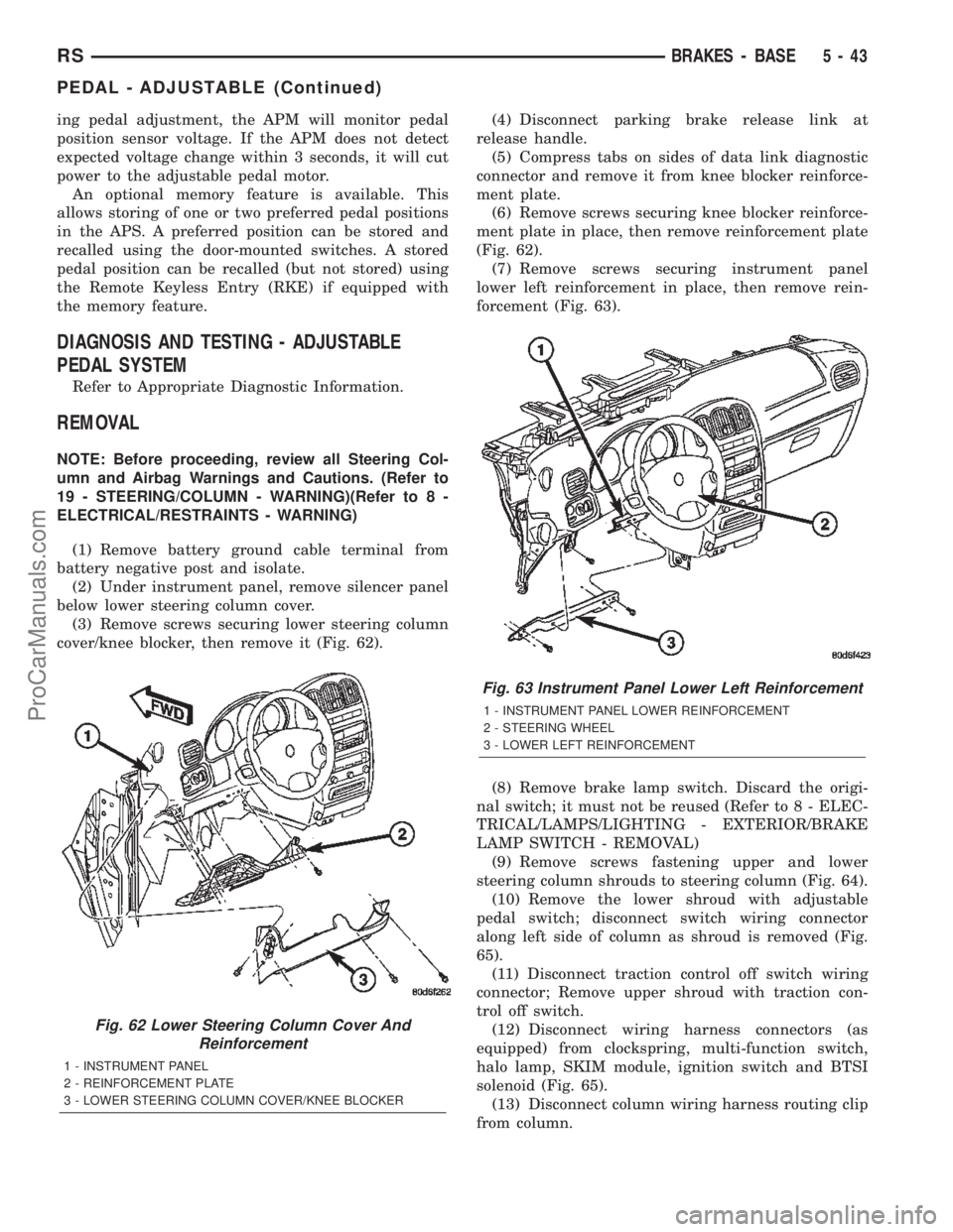
(3) Remove screws securing lower steering column
cover/knee blocker, then remove it (Fig. 62).(4) Disconnect parking brake release link at
release handle.
(5) Compress tabs on sides of data link diagnostic
connector and remove it from knee blocker reinforce-
ment plate.
(6) Remove screws securing knee blocker reinforce-
ment plate in place, then remove reinforcement plate
(Fig. 62).
(7) Remove screws securing instrument panel
lower left reinforcement in place, then remove rein-
forcement (Fig. 63).
(8) Remove brake lamp switch. Discard the origi-
nal switch; it must not be reused (Refer to 8 - ELEC-
TRICAL/LAMPS/LIGHTING - EXTERIOR/BRAKE
LAMP SWITCH - REMOVAL)
(9) Remove screws fastening upper and lower
steering column shrouds to steering column (Fig. 64).
(10) Remove the lower shroud with adjustable
pedal switch; disconnect switch wiring connector
along left side of column as shroud is removed (Fig.
65).
(11) Disconnect traction control off switch wiring
connector; Remove upper shroud with traction con-
trol off switch.
(12) Disconnect wiring harness connectors (as
equipped) from clockspring, multi-function switch,
halo lamp, SKIM module, ignition switch and BTSI
solenoid (Fig. 65).
(13) Disconnect column wiring harness routing clip
from column.
Fig. 62 Lower Steering Column Cover And
Reinforcement
1 - INSTRUMENT PANEL
2 - REINFORCEMENT PLATE
3 - LOWER STEERING COLUMN COVER/KNEE BLOCKER
Fig. 63 Instrument Panel Lower Left Reinforcement
1 - INSTRUMENT PANEL LOWER REINFORCEMENT
2 - STEERING WHEEL
3 - LOWER LEFT REINFORCEMENT
RSBRAKES - BASE5-43
PEDAL - ADJUSTABLE (Continued)
ProCarManuals.com
Page 186 of 2399
OPERATION - PROPORTIONING VALVE
(HEIGHT SENSING)
Vehicles not equipped with ABS use a height sens-
ing proportioning valve.
The height sensing proportioning valve operates
similarly to a standard proportioning valve in the fol-
lowing way. As hydraulic pressure is applied to the
valve, full input hydraulic pressure is supplied to the
rear brakes up to a certain pressure point, called the
split point. Beyond the split point, the proportioning
valve reduces the amount of hydraulic pressure to
the rear brakes according to a given ratio. Thus, on
light brake applications, approximately equal
hydraulic pressure will be transmitted to both the
front and rear brakes. Upon heavier brake applica-
tions, the hydraulic pressure transmitted to the rear
brakes will be lower than the front brakes. This will
prevent premature rear wheel lockup and skid.
Here is how the height sensing proportioning valve
differs from a standard proportioning valve. As the
height of the rear suspension changes, the height
sensing portion of the proportioning valve changes
the split point of the proportioning valve. When the
height of the rear suspension is low, the proportion-
ing valve interprets this as extra load and the split
point of the proportioning valve is raised to a higher
pressure to allow for more rear braking. When the
height of the rear suspension is high, the proportion-
ing valve interprets this as a light load and the split
point of the proportioning valve is lowered to a lower
pressure and rear braking is reduced.
The height sensing proportioning valve regulates
the pressure by sensing the load condition of the
vehicle through the movement of the proportioning
valve actuator lever (Fig. 91). As the position of the
rear axle changes, depending on the load the vehicle
is carrying, the movement is transferred to the pro-
portioning valve. The proportioning valve adjusts the
hydraulic pressure accordingly.
The height sensing proportioning valve allows the
brake system to maintain the optimal front to rear
brake balance regardless of the vehicle load condi-
tion. Under a light load condition, hydraulic pressure
to the rear brakes is minimized. As the rear load con-
dition increases, so does the hydraulic pressure to
the rear brakes.
DIAGNOSIS AND TESTING - PROPORTIONING
VALVE (HEIGHT SENSING)
CAUTION: The use of aftermarket load leveling or
load capacity increasing devices on this vehicle is
prohibited. Using air shock absorbers or helper
springs on this vehicle will cause the height sens-
ing proportioning valve to inappropriately reduce
the hydraulic pressure to the rear brakes. This inap-propriate reduction in hydraulic pressure potentially
could result in increased stopping distance of the
vehicle.
When a premature rear wheel skid is obtained on a
brake application, it may be an indication that the
hydraulic pressure to the rear brakes is above the
specified output from the proportioning valve. This
condition indicates a possible malfunction of the
height sensing proportioning valve, which will
require testing to verify that it is properly controlling
the hydraulic pressure allowed to the rear brakes.
Premature rear wheel skid may also be caused by
contaminated front or rear brake linings.
Prior to testing a proportioning valve for function,
check that all tire pressures are correct. Also, ensure
the front and rear brake linings are in satisfactory
condition.It is also necessary to verify that the
brakes shoe assemblies on a vehicle being
tested are either original equipment manufac-
turers (OEM) or original replacement brake
shoe assemblies meeting the OEM lining mate-
rial specification. This vehicles brake system is
not balanced for aftermarket brake shoe assem-
bly lining material.
If both front and rear brakes check OK, proceed
with the following test procedure for the height sens-
ing proportioning valve.
(1) Road test the vehicle to determine which rear
wheel brake is exhibiting premature wheel skid.
(2) Raise vehicle. (Refer to LUBRICATION &
MAINTENANCE/HOISTING - STANDARD PROCE-
DURE)
(3) Remove the chassis brake tube going to the
rear brake in question at the proportioning valve.
Remove the chassis brake tube coming from the junc-
tion block at the proportioning valve (Fig. 92).
(4) Install the appropriate fittings from Pressure
Test Fittings, Special Tool 6833, into the open ports
of the proportioning valve.
(5) Install the previously removed brake lines into
the Pressure Test Fittings. Tighten all tube nuts to
17 N´m (145 in. lbs.).
(6) Install a pressure gauge from Gauge Set, Spe-
cial Tool C-4007-A into the open port on each pres-
sure test fitting. Bleed air out of hose from pressure
test fittings to pressure gauges at the pressure
gauges. Then bleed air out of the brake line being
tested at that rear wheel brake bleeder.
NOTE: Actuator rod is a linear spring and is meant
to flex by design. When rod is raised, it will have
some curvature to it.
(7) Remove the screw fastening the proportioning
valve actuator rod bracket to the rear axle. Raise the
actuator lever to the full-upward position and hold it
there.
RSBRAKES - BASE5-57
PROPORTIONING VALVE (Continued)
ProCarManuals.com
Page 321 of 2399
information and location views for the various wire
harness connectors, splices and grounds.
WARNING: ON VEHICLES EQUIPPED WITH AIR-
BAGS, REFER TO ELECTRICAL, RESTRAINTS
BEFORE ATTEMPTING ANY STEERING WHEEL,STEERING COLUMN, OR INSTRUMENT PANEL
COMPONENT DIAGNOSIS OR SERVICE. FAILURE
TO TAKE THE PROPER PRECAUTIONS COULD
RESULT IN ACCIDENTAL AIRBAG DEPLOYMENT
AND POSSIBLE PERSONAL INJURY.
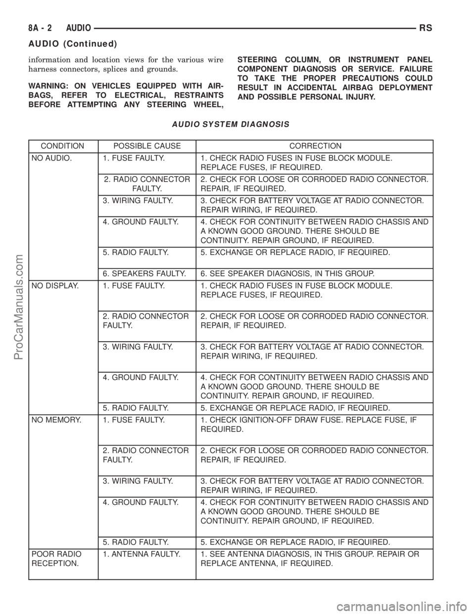
AUDIO SYSTEM DIAGNOSIS
CONDITION POSSIBLE CAUSE CORRECTION
NO AUDIO. 1. FUSE FAULTY. 1. CHECK RADIO FUSES IN FUSE BLOCK MODULE.
REPLACE FUSES, IF REQUIRED.
2. RADIO CONNECTOR
FAULTY.2. CHECK FOR LOOSE OR CORRODED RADIO CONNECTOR.
REPAIR, IF REQUIRED.
3. WIRING FAULTY. 3. CHECK FOR BATTERY VOLTAGE AT RADIO CONNECTOR.
REPAIR WIRING, IF REQUIRED.
4. GROUND FAULTY. 4. CHECK FOR CONTINUITY BETWEEN RADIO CHASSIS AND
A KNOWN GOOD GROUND. THERE SHOULD BE
CONTINUITY. REPAIR GROUND, IF REQUIRED.
5. RADIO FAULTY. 5. EXCHANGE OR REPLACE RADIO, IF REQUIRED.
6. SPEAKERS FAULTY. 6. SEE SPEAKER DIAGNOSIS, IN THIS GROUP.
NO DISPLAY. 1. FUSE FAULTY. 1. CHECK RADIO FUSES IN FUSE BLOCK MODULE.
REPLACE FUSES, IF REQUIRED.
2. RADIO CONNECTOR
FAULTY.2. CHECK FOR LOOSE OR CORRODED RADIO CONNECTOR.
REPAIR, IF REQUIRED.
3. WIRING FAULTY. 3. CHECK FOR BATTERY VOLTAGE AT RADIO CONNECTOR.
REPAIR WIRING, IF REQUIRED.
4. GROUND FAULTY. 4. CHECK FOR CONTINUITY BETWEEN RADIO CHASSIS AND
A KNOWN GOOD GROUND. THERE SHOULD BE
CONTINUITY. REPAIR GROUND, IF REQUIRED.
5. RADIO FAULTY. 5. EXCHANGE OR REPLACE RADIO, IF REQUIRED.
NO MEMORY. 1. FUSE FAULTY. 1. CHECK IGNITION-OFF DRAW FUSE. REPLACE FUSE, IF
REQUIRED.
2. RADIO CONNECTOR
FAULTY.2. CHECK FOR LOOSE OR CORRODED RADIO CONNECTOR.
REPAIR, IF REQUIRED.
3. WIRING FAULTY. 3. CHECK FOR BATTERY VOLTAGE AT RADIO CONNECTOR.
REPAIR WIRING, IF REQUIRED.
4. GROUND FAULTY. 4. CHECK FOR CONTINUITY BETWEEN RADIO CHASSIS AND
A KNOWN GOOD GROUND. THERE SHOULD BE
CONTINUITY. REPAIR GROUND, IF REQUIRED.
5. RADIO FAULTY. 5. EXCHANGE OR REPLACE RADIO, IF REQUIRED.
POOR RADIO
RECEPTION.1. ANTENNA FAULTY. 1. SEE ANTENNA DIAGNOSIS, IN THIS GROUP. REPAIR OR
REPLACE ANTENNA, IF REQUIRED.
8A - 2 AUDIORS
AUDIO (Continued)
ProCarManuals.com
Page 327 of 2399
NOTE: Use care when inserting CD changer so that
cable is not pinched or trapped against instrument
panel.
(3) Install screws holding CD changer.
(4) Reconnect the battery negative cable.
INSTRUMENT PANEL
ANTENNA CABLE
REMOVAL
WARNING: ON VEHICLES EQUIPPED WITH AIR-
BAGS, REFER TO ELECTRICAL, RESTRAINTS
BEFORE ATTEMPTING ANY STEERING WHEEL,
STEERING COLUMN, OR INSTRUMENT PANEL
COMPONENT DIAGNOSIS OR SERVICE. FAILURE
TO TAKE THE PROPER PRECAUTIONS COULD
RESULT IN ACCIDENTAL AIRBAG DEPLOYMENT
AND POSSIBLE PERSONAL INJURY.
(1) Disconnect and isolate the battery negative
cable.
(2) Remove glove box (Refer to 23 - BODY/IN-
STRUMENT PANEL/GLOVE BOX - REMOVAL).
(3) Disconnect extension cable end from antenna
cable end.
(4) Disconnect cable hanger clip from HVAC unit.
(5) Remove radio as necessary to gain access to
extension cable (Refer to 8 - ELECTRICAL/AUDIO/
RADIO - REMOVAL).
(6) Disconnect extension cable from back of radio.
(7) Remove extension cable from vehicle.
INSTALLATION
(1) Install extension cable to vehicle.
(2) Connect extension cable to back of radio.
(3) Install radio (Refer to 8 - ELECTRICAL/AU-
DIO/RADIO - INSTALLATION).
(4) Connect cable hanger clip to HVAC unit.
(5) Connect extension cable end to antenna cable
end.
(6) Install glove box (Refer to 23 - BODY/INSTRU-
MENT PANEL/GLOVE BOX - INSTALLATION).
(7) Connect the battery negative cable.
QUARTER GLASS INTEGRAL
ANTENNA - EXPORT
DESCRIPTION
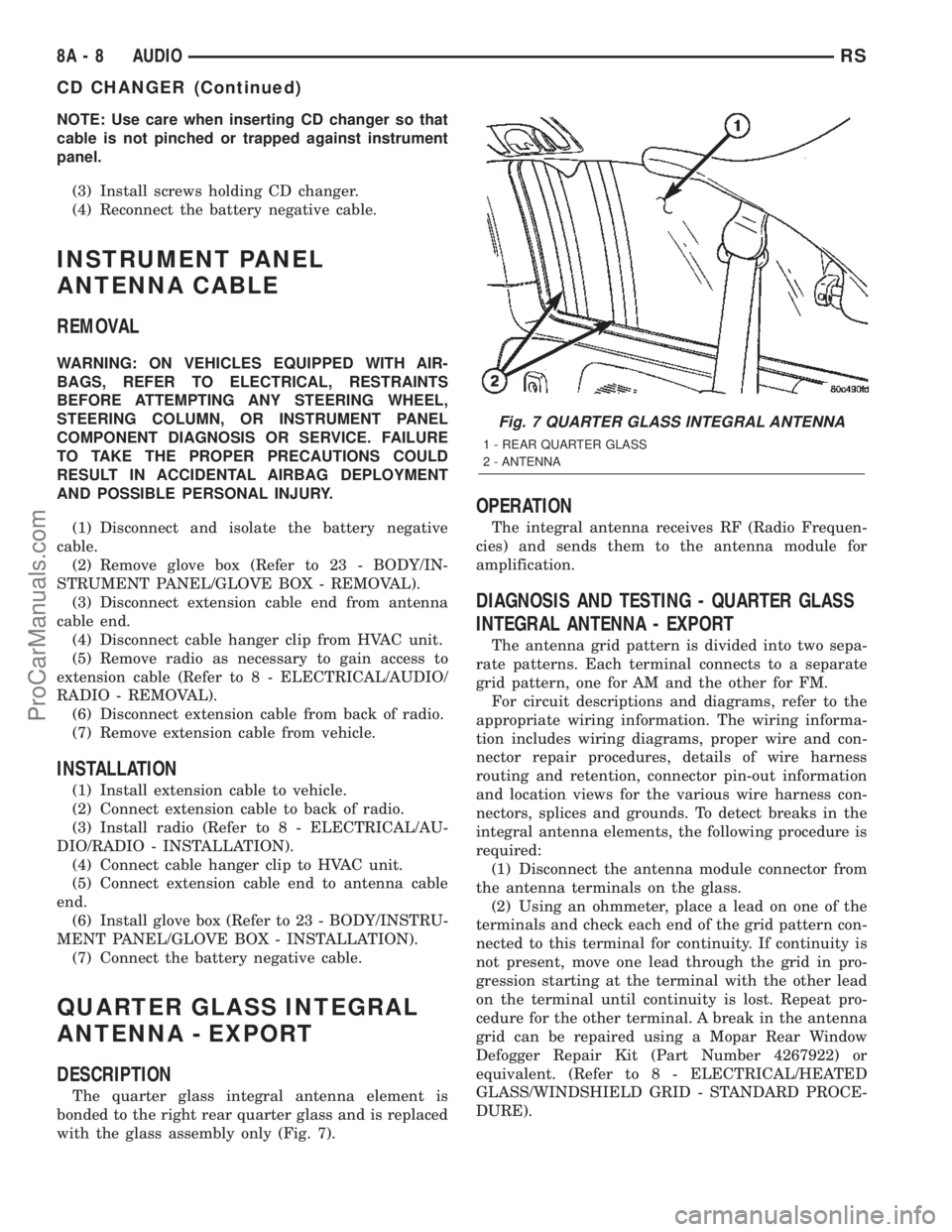
The quarter glass integral antenna element is
bonded to the right rear quarter glass and is replaced
with the glass assembly only (Fig. 7).
OPERATION
The integral antenna receives RF (Radio Frequen-
cies) and sends them to the antenna module for
amplification.
DIAGNOSIS AND TESTING - QUARTER GLASS
INTEGRAL ANTENNA - EXPORT
The antenna grid pattern is divided into two sepa-
rate patterns. Each terminal connects to a separate
grid pattern, one for AM and the other for FM.
For circuit descriptions and diagrams, refer to the
appropriate wiring information. The wiring informa-
tion includes wiring diagrams, proper wire and con-
nector repair procedures, details of wire harness
routing and retention, connector pin-out information
and location views for the various wire harness con-
nectors, splices and grounds. To detect breaks in the
integral antenna elements, the following procedure is
required:
(1) Disconnect the antenna module connector from
the antenna terminals on the glass.
(2) Using an ohmmeter, place a lead on one of the
terminals and check each end of the grid pattern con-
nected to this terminal for continuity. If continuity is
not present, move one lead through the grid in pro-
gression starting at the terminal with the other lead
on the terminal until continuity is lost. Repeat pro-
cedure for the other terminal. A break in the antenna
grid can be repaired using a Mopar Rear Window
Defogger Repair Kit (Part Number 4267922) or
equivalent. (Refer to 8 - ELECTRICAL/HEATED
GLASS/WINDSHIELD GRID - STANDARD PROCE-
DURE).
Fig. 7 QUARTER GLASS INTEGRAL ANTENNA
1 - REAR QUARTER GLASS
2 - ANTENNA
8A - 8 AUDIORS
CD CHANGER (Continued)
ProCarManuals.com
Page 328 of 2399
RADIO
DIAGNOSIS AND TESTING - RADIO
WARNING: ON VEHICLES EQUIPPED WITH AIR-
BAGS, REFER TO ELECTRICAL, RESTRAINTS
BEFORE ATTEMPTING ANY STEERING WHEEL,
STEERING COLUMN, OR INSTRUMENT PANEL
COMPONENT DIAGNOSIS OR SERVICE. FAILURE
TO TAKE THE PROPER PRECAUTIONS COULD
RESULT IN ACCIDENTAL AIRBAG DEPLOYMENT
AND POSSIBLE PERSONAL INJURY.
Any diagnosis of the Audio system should
begin with the use of the DRB IIItdiagnostic
tool. For information on the use of the DRB
IIIt, refer to the appropriate Diagnostic Service
Manual.
Refer to the appropriate wiring information. The
wiring information includes wiring diagrams, proper
wire and connector repair procedures, details of wire
harness routing and retention, connector pin-out
information and location views for the various wire
harness connectors, splices and grounds.
If the vehicle is equipped with remote radio
switches located on the back of the steering wheel
spokes, and the problem being diagnosed is related to
one of the symptoms listed below, be certain to check
the remote radio switches and circuits as described
in this group, prior to attempting radio diagnosis or
repair.
²Stations changing with no remote radio switch
input
²Radio memory presets not working properly
²Volume changes with no remote radio switch
input
²Remote radio switch buttons taking on other
functions
²CD player skipping tracks
²Remote radio switch inoperative.
CAUTION: The speaker output of the radio is a
ªfloating groundº system. Do not allow any speaker
lead to short to ground, as damage to the radio
may result.
(1) Check the fuse(s) in the junction block and the
Integrated Power Module (IPM). If OK, go to Step 2.
If not OK, repair the shorted circuit or component as
required and replace the faulty fuse(s).
(2) Check for battery voltage at the fuse in the
(IPM). If OK, go to Step 3. If not OK, repair the open
circuit to the battery as required.
(3) Turn the ignition switch to the ON position.
Check for battery voltage at the fuse in the junction
block. If OK, go to Step 4. If not OK, repair the open
circuit to the ignition switch as required.(4) Turn the ignition switch to the OFF position.
Remove the radio, but do not unplug the wire har-
ness connectors. Check for continuity between the
radio chassis and a good ground. There should be
continuity. If OK, go to Step 5. If not OK, repair the
open radio chassis ground circuit as required.
(5) Connect the battery negative cable. Turn the
ignition switch to the ON position. Check for battery
voltage at the fused ignition switch output circuit
cavity of the radio wire harness connector. If OK, go
to Step 6. If not OK, repair the open circuit as
required.
(6) Turn the ignition switch to the OFF position.
Check for battery voltage at the fused B(+) circuit
cavity of the radio wire harness connector. If OK,
replace the faulty radio. If not OK, repair the open
circuit to the Ignition-Off Draw (IOD) fuse as
required.
REMOVAL
(1) Disconnect and isolate the battery negative
cable.
(2) Remove cup holder.
(3) Remove trim panel above cupholder by pulling
straight out.
(4) Remove center instrument panel trim panel.
(5) Remove screws holding radio to instrument
panel.
(6) Pull radio rearward to gain access to the back
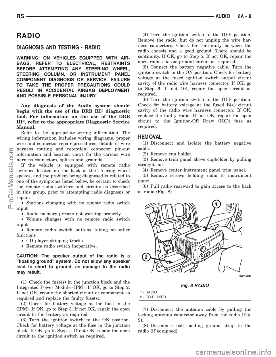
of radio (Fig. 8).
(7) Disconnect the antenna cable by pulling the
locking antenna connector away from the radio (Fig.
9).
(8) Disconnect bolt holding ground strap to the
radio (if equipped).
Fig. 8 RADIO
1 - RADIO
2 - CD-PLAYER
RSAUDIO8A-9
ProCarManuals.com
Page 330 of 2399
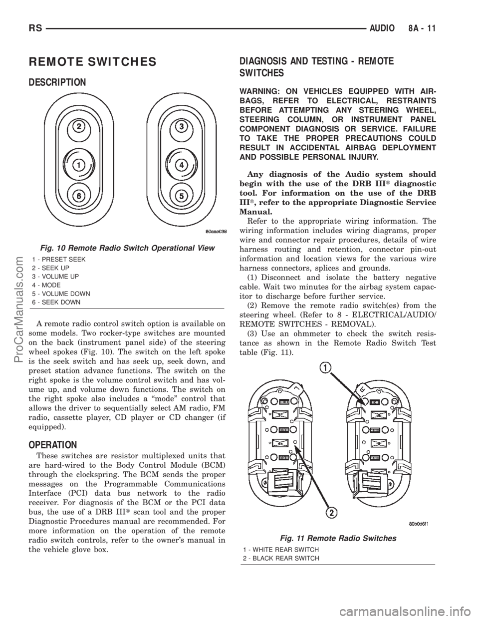
REMOTE SWITCHES
DESCRIPTION
A remote radio control switch option is available on
some models. Two rocker-type switches are mounted
on the back (instrument panel side) of the steering
wheel spokes (Fig. 10). The switch on the left spoke
is the seek switch and has seek up, seek down, and
preset station advance functions. The switch on the
right spoke is the volume control switch and has vol-
ume up, and volume down functions. The switch on
the right spoke also includes a ªmodeº control that
allows the driver to sequentially select AM radio, FM
radio, cassette player, CD player or CD changer (if
equipped).
OPERATION
These switches are resistor multiplexed units that
are hard-wired to the Body Control Module (BCM)
through the clockspring. The BCM sends the proper
messages on the Programmable Communications
Interface (PCI) data bus network to the radio
receiver. For diagnosis of the BCM or the PCI data
bus, the use of a DRB IIItscan tool and the proper
Diagnostic Procedures manual are recommended. For
more information on the operation of the remote
radio switch controls, refer to the owner's manual in
the vehicle glove box.
DIAGNOSIS AND TESTING - REMOTE
SWITCHES
WARNING: ON VEHICLES EQUIPPED WITH AIR-
BAGS, REFER TO ELECTRICAL, RESTRAINTS
BEFORE ATTEMPTING ANY STEERING WHEEL,
STEERING COLUMN, OR INSTRUMENT PANEL
COMPONENT DIAGNOSIS OR SERVICE. FAILURE
TO TAKE THE PROPER PRECAUTIONS COULD
RESULT IN ACCIDENTAL AIRBAG DEPLOYMENT
AND POSSIBLE PERSONAL INJURY.
Any diagnosis of the Audio system should
begin with the use of the DRB IIItdiagnostic
tool. For information on the use of the DRB
IIIt, refer to the appropriate Diagnostic Service
Manual.
Refer to the appropriate wiring information. The
wiring information includes wiring diagrams, proper
wire and connector repair procedures, details of wire
harness routing and retention, connector pin-out
information and location views for the various wire
harness connectors, splices and grounds.
(1) Disconnect and isolate the battery negative
cable. Wait two minutes for the airbag system capac-
itor to discharge before further service.
(2) Remove the remote radio switch(es) from the
steering wheel. (Refer to 8 - ELECTRICAL/AUDIO/
REMOTE SWITCHES - REMOVAL).
(3) Use an ohmmeter to check the switch resis-
tance as shown in the Remote Radio Switch Test
table (Fig. 11).
Fig. 10 Remote Radio Switch Operational View
1 - PRESET SEEK
2 - SEEK UP
3 - VOLUME UP
4 - MODE
5 - VOLUME DOWN
6 - SEEK DOWN
Fig. 11 Remote Radio Switches
1 - WHITE REAR SWITCH
2 - BLACK REAR SWITCH
RSAUDIO8A-11
ProCarManuals.com
Page 522 of 2399
(4) Reconnect the battery negative cable.
LICENSE LAMP
REMOVAL
(1) Disconnect and isolate the battery negative
cable.
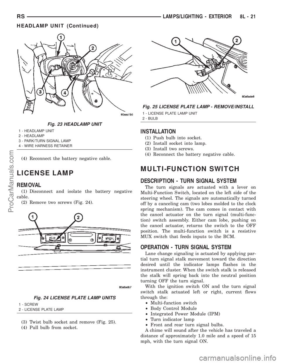
(2) Remove two screws (Fig. 24).
(3) Twist bulb socket and remove (Fig. 25).
(4) Pull bulb from socket.
INSTALLATION
(1) Push bulb into socket.
(2) Install socket into lamp.
(3) Install two screws.
(4) Reconnect the battery negative cable.
MULTI-FUNCTION SWITCH
DESCRIPTION - TURN SIGNAL SYSTEM
The turn signals are actuated with a lever on
Multi-Function Switch, located on the left side of the
steering wheel. The signals are automatically turned
off by a canceling cam (two lobes molded to the clock
spring mechanism). The cam comes in contact with
the cancel actuator on the turn signal (multi-func-
tion) switch assembly. Either cam lobe, pushing on
the cancel actuator, returns the switch to the OFF
position. The multi-function switch is a resistive
MUX switch that feeds inputs to the BCM.
OPERATION - TURN SIGNAL SYSTEM
Lane change signaling is actuated by applying par-
tial turn signal stalk movement toward the direction
desired until the indicator lamps flashes in the
instrument cluster. When the switch stalk is released
the stalk will spring back into the neutral position
turning OFF the turn signal.
With the ignition switch ON and the turn signal
switch stalk actuated left or right, current flows
through the:
²Multi-function switch
²Body Control Module
²Integrated Power Module (IPM)
²Turn indicator lamp
²Front and rear turn signal bulbs.
A chime will sound after the vehicle has traveled a
distance of approximately 1.0 mile and a speed of 15
mph, with the turn signal ON.
Fig. 23 HEADLAMP UNIT
1 - HEADLAMP UNIT
2 - HEADLAMP
3 - PARK/TURN SIGNAL LAMP
4 - WIRE HARNESS RETAINER
Fig. 24 LICENSE PLATE LAMP UNITS
1 - SCREW
2 - LICENSE PLATE LAMP
Fig. 25 LICENSE PLATE LAMP - REMOVE/INSTALL
1 - LICENSE PLATE LAMP UNIT
2 - BULB
RSLAMPS/LIGHTING - EXTERIOR8L-21
HEADLAMP UNIT (Continued)
ProCarManuals.com