cruise control CHRYSLER CARAVAN 2002 Service Manual
[x] Cancel search | Manufacturer: CHRYSLER, Model Year: 2002, Model line: CARAVAN, Model: CHRYSLER CARAVAN 2002Pages: 2399, PDF Size: 57.96 MB
Page 171 of 2399
(5) Install wiring harness connector to brake fluid
level switch mounted in brake fluid reservoir (Fig.
57).
(6) Install battery, clamp and nut.
(7) Install battery shield.
(8) Connect positive battery terminal.
(9) Connect negative battery terminal.
(10) Fill master cylinder with clean, fresh Mopart
Brake Fluid or equivalent.
(11) Road test vehicle to ensure proper operation of
brakes.
INSTALLATION - RHD
CAUTION: Different types of master cylinders are
used on this vehicle depending on brake options. If
a new master cylinder is being installed, be sure it
is the correct master cylinder for the type of brake
system the vehicle is equipped with.
CAUTION: When replacing the master cylinder on a
vehicle, a NEW vacuum seal MUST be installed on
the master cylinder.
(1) Install a NEW vacuum seal on master cylinder
making sure seal fits squarely in groove of master
cylinder casting.
(2) Position master cylinder on studs of power
brake booster, aligning booster push rod with master
cylinder piston.
(3) Install the two master cylinder mounting nuts
(Fig. 59). Tighten both mounting nuts to a torque of
25 N´m (225 in. lbs.).
CAUTION: When tightening the primary and sec-
ondary brake tube nuts at master cylinder, be sure
brake tubes do not contact any other components
within the vehicle and that there is slack in the flex-
ible sections of the tubes. This is required due to
the movement between the ABS ICU and the master
cylinder while the vehicle is in motion.
(4) Connect primary and secondary brake tubes to
master cylinder primary and secondary ports (Fig.
59). Brake tubes must be held securely when tight-
ened to control orientation of flex section. Tighten
tube nuts to a torque of 17 N´m (145 in. lbs.).
(5) Install wiring harness connector to brake fluid
level switch mounted in brake fluid reservoir (Fig.
55).
(6) Install battery, clamp and nut.
(7) Install battery shield.
(8) Connect positive battery terminal.
(9) Connect negative battery terminal.
(10) Fill master cylinder with clean, fresh Mopart
Brake Fluid or equivalent.(11) Road test vehicle to ensure proper operation of
brakes.
PEDAL - ADJUSTABLE
DESCRIPTION
The Adjustable Pedals System (APS) is designed to
enable the fore and aft repositioning of the brake and
accelerator pedals. This results in improved ergonom-
ics in relation to the steering wheel for taller and
shorter drivers. Being able to adjust the pedal posi-
tions also allows the driver to set steering wheel tilt
and seat position to the most comfortable position.
The effort required for pedal application will not
change regardless of pedal position.
The adjustable pedal system allows the pedals to
adjust up to 3 inches (75 mm) at a rate of approxi-
mately 0.4 in./sec. (9 mm/sec.). An adjustment switch
is located on the left side of the steering column
lower shroud.
If the vehicle is equipped with Remote Keyless
Entry (RKE), an optional memory feature is avail-
able.
The serviceable components of the APS are:
²Adjustable pedal assembly (includes motor,
cables, pedals, gear box, sensor and module)
²Adjustable pedal module (Refer to 8 - ELECTRI-
CAL/ELECTRONIC CONTROL MODULES/
ADJUSTABLE PEDAL MODULE)
²Adjustable pedal switch
²Pedal position sensor
OPERATION
Change of pedal position is accomplished by means
of a motor driven screw. Operating the adjustable
pedal switch activates the pedal drive motor. The
pedal drive motor turns a screw that changes the
position of the accelerator pedal. The motor also
drives a cable connected to a gear box that changes
the brake pedal position the same distance as the
accelerator pedal. The pedals can be moved rearward
(closer to the driver) or forward (away from driver).
Each pedal is moved on its activating lever to a posi-
tion where the driver feels most comfortable. The
position and operation of the activating levers are not
changed.
Pedal adjustment is inhibited when the vehicle is
in reverse or when cruise control is engaged. The
Electronic Vehicle Information Center (EVIC) will
display a message when the Adjustable Pedal Module
(APM) is disabled. i.e.:9Adjustable Pedal Disabled -
Cruise Control Engaged9or9Adjustable Pedal Dis-
abled - Vehicle in Reverse9.
Foot pressure or debris can stall pedal adjustment.
In order to avoid damage to system components dur-
5 - 42 BRAKES - BASERS
MASTER CYLINDER (Continued)
ProCarManuals.com
Page 356 of 2399
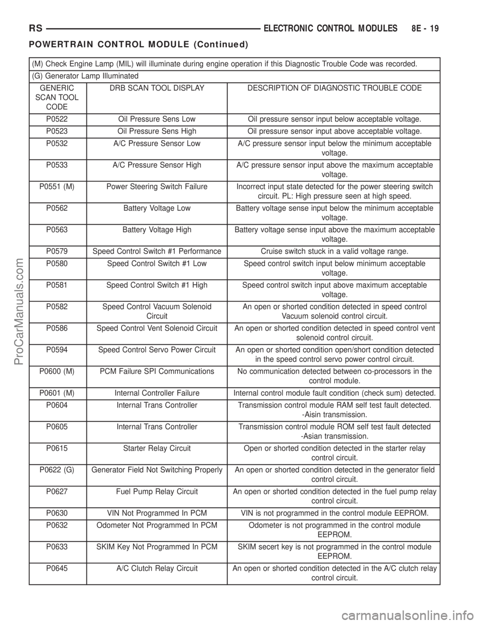
(M) Check Engine Lamp (MIL) will illuminate during engine operation if this Diagnostic Trouble Code was recorded.
(G) Generator Lamp Illuminated
GENERIC
SCAN TOOL
CODEDRB SCAN TOOL DISPLAY DESCRIPTION OF DIAGNOSTIC TROUBLE CODE
P0522 Oil Pressure Sens Low Oil pressure sensor input below acceptable voltage.
P0523 Oil Pressure Sens High Oil pressure sensor input above acceptable voltage.
P0532 A/C Pressure Sensor Low A/C pressure sensor input below the minimum acceptable
voltage.
P0533 A/C Pressure Sensor High A/C pressure sensor input above the maximum acceptable
voltage.
P0551 (M) Power Steering Switch Failure Incorrect input state detected for the power steering switch
circuit. PL: High pressure seen at high speed.
P0562 Battery Voltage Low Battery voltage sense input below the minimum acceptable
voltage.
P0563 Battery Voltage High Battery voltage sense input above the maximum acceptable
voltage.
P0579 Speed Control Switch #1 Performance Cruise switch stuck in a valid voltage range.
P0580 Speed Control Switch #1 Low Speed control switch input below minimum acceptable
voltage.
P0581 Speed Control Switch #1 High Speed control switch input above maximum acceptable
voltage.
P0582 Speed Control Vacuum Solenoid
CircuitAn open or shorted condition detected in speed control
Vacuum solenoid control circuit.
P0586 Speed Control Vent Solenoid Circuit An open or shorted condition detected in speed control vent
solenoid control circuit.
P0594 Speed Control Servo Power Circuit An open or shorted condition open/short condition detected
in the speed control servo power control circuit.
P0600 (M) PCM Failure SPI Communications No communication detected between co-processors in the
control module.
P0601 (M) Internal Controller Failure Internal control module fault condition (check sum) detected.
P0604 Internal Trans Controller Transmission control module RAM self test fault detected.
-Aisin transmission.
P0605 Internal Trans Controller Transmission control module ROM self test fault detected
-Asian transmission.
P0615 Starter Relay Circuit Open or shorted condition detected in the starter relay
control circuit.
P0622 (G) Generator Field Not Switching Properly An open or shorted condition detected in the generator field
control circuit.
P0627 Fuel Pump Relay Circuit An open or shorted condition detected in the fuel pump relay
control circuit.
P0630 VIN Not Programmed In PCM VIN is not programmed in the control module EEPROM.
P0632 Odometer Not Programmed In PCM Odometer is not programmed in the control module
EEPROM.
P0633 SKIM Key Not Programmed In PCM SKIM secert key is not programmed in the control module
EEPROM.
P0645 A/C Clutch Relay Circuit An open or shorted condition detected in the A/C clutch relay
control circuit.
RSELECTRONIC CONTROL MODULES8E-19
POWERTRAIN CONTROL MODULE (Continued)
ProCarManuals.com
Page 488 of 2399
INSTRUMENT CLUSTER
TABLE OF CONTENTS
page page
INSTRUMENT CLUSTER
DESCRIPTION..........................1
OPERATION............................1
DIAGNOSIS AND TESTING
DIAGNOSIS AND TESTING - SELF-
DIAGNOSTICS.........................2
DIAGNOSIS AND TESTING - CLUSTER
DIAGNOSIS...........................2
REMOVAL.............................11
INSTALLATION.........................12CLUSTER LENS
REMOVAL.............................12
INSTALLATION.........................12
MECHANICAL TRANSMISSION RANGE
INDICATOR
REMOVAL.............................12
INSTALLATION.........................12
RED BRAKE WARNING INDICATOR
DESCRIPTION.........................13
OPERATION...........................13
INSTRUMENT CLUSTER
DESCRIPTION
The instrumentation gauges are contained in a
subdial assembly within the instrument cluster. The
individual gauges are not serviceable. If one of the
cluster gauges becomes faulty, the entire cluster
would require replacement.
The mechanical instrument cluster with a tachom-
eter is equipped with a electronic vacuum fluorescent
transmission range indicator (PRND3L), odometer,
and trip odometer display.
The mechanical instrument cluster without a
tachometer is equipped with a cable operated trans-
mission range indicator (PRND21) and a vacuum flu-
orescent odometer display. It also has the following
indicators:
²Turn Signals
²High Beam
²Oil Pressure
²MIL
The instrument cluster is equipped with the follow-
ing warning lamps.
²Lift Gate Ajar
²Low Fuel Level
²Low Windshield Washer Fluid Level
²Cruise
²Battery Voltage
²Fasten Seat Belt
²Door Ajar
²Coolant Temperature
²Anti-Lock Brake
²Brake
²Airbag
²Traction Control
²AutostickThe mechanical instrument cluster without a
tachometer also has the following warning lamps:
²Turns Signals
²High Beam
²Oil Pressure
²Malfunction Indicator Lamp (MIL)
WATER IN FUEL LAMP - EXPORT
The Water In Fuel Lamp is located in the instru-
ment cluster. When moisture is found within the fuel
system, the sensor sends a message via the PCI data
bus to the instrument cluster. The sensor is located
underneath the vehicle, directly above the rear axle.
The sensor is housed within the fuel filter/water sep-
arator assembly cover. The sensor is not serviced sep-
arately. If found defective, the entire assembly cover
must be replaced.
OPERATION
Refer to the vehicle Owner's Manual for operation
instructions and conditions for the Instrument Clus-
ter Gauges.
WATER IN FUEL LAMP - EXPORT
The Water In Fuel Sensor is a resistive type
switch. It is calibrated to sense the different resis-
tance between diesel fuel and water. When water
enters the fuel system, it is caught in the bottom of
the fuel filter/water separator assembly, where the
sensor is located. Water has less resistance than die-
sel fuel. The sensor then sends a PCI data bus mes-
sage to the instrument cluster to illuminate the
lamp.
If the lamp is inoperative, perform the self diag-
nostic test on the instrument cluster to check the
lamp operation before continuing diagnosis.
RSINSTRUMENT CLUSTER8J-1
ProCarManuals.com
Page 1468 of 2399
FUEL INJECTION
OPERATION
OPERATION - INJECTION SYSTEM
All engines used in this section have a sequential
Multi-Port Electronic Fuel Injection system. The MPI
system is computer regulated and provides precise
air/fuel ratios for all driving conditions. The Power-
train Control Module (PCM) operates the fuel injec-
tion system.
The PCM regulates:
²Ignition timing
²Air/fuel ratio
²Emission control devices
²Cooling fan
²Charging system
²Idle speed
²Vehicle speed control
Various sensors provide the inputs necessary for
the PCM to correctly operate these systems. In addi-
tion to the sensors, various switches also provide
inputs to the PCM.
The PCM can adapt its programming to meet
changing operating conditions.
Fuel is injected into the intake port above the
intake valve in precise metered amounts through
electrically operated injectors. The PCM fires the
injectors in a specific sequence. Under most operat-
ing conditions, the PCM maintains an air fuel ratio
of 14.7 parts air to 1 part fuel by constantly adjust-
ing injector pulse width. Injector pulse width is the
length of time the injector is open.
The PCM adjusts injector pulse width by opening
and closing the ground path to the injector. Engine
RPM (speed) and manifold absolute pressure (air
density) are theprimaryinputs that determine
injector pulse width.
OPERATION - MODES OF OPERATION
As input signals to the PCM change, the PCM
adjusts its response to output devices. For example,
the PCM must calculate a different injector pulse
width and ignition timing for idle than it does for
Wide Open Throttle (WOT). There are several differ-
ent modes of operation that determine how the PCM
responds to the various input signals.
There are two different areas of operation, OPEN
LOOP and CLOSED LOOP.
During OPEN LOOP modes the PCM receives
input signals and responds according to preset PCM
programming. Inputs from the upstream and down-
stream heated oxygen sensors are not monitored dur-
ing OPEN LOOP modes, except for heated oxygensensor diagnostics (they are checked for shorted con-
ditions at all times).
During CLOSED LOOP modes the PCM monitors
the inputs from the upstream and downstream
heated oxygen sensors. The upstream heated oxygen
sensor input tells the PCM if the calculated injector
pulse width resulted in the ideal air-fuel ratio of 14.7
to one. By monitoring the exhaust oxygen content
through the upstream heated oxygen sensor, the
PCM can fine tune injector pulse width. Fine tuning
injector pulse width allows the PCM to achieve opti-
mum fuel economy combined with low emissions.
For the PCM to enter CLOSED LOOP operation,
the following must occur:
(1) Engine coolant temperature must be over 35ÉF.
²If the coolant is over 35ÉF the PCM will wait 38
seconds.
²If the coolant is over 50ÉF the PCM will wait 15
seconds.
²If the coolant is over 167ÉF the PCM will wait 3
seconds.
(2) For other temperatures the PCM will interpo-
late the correct waiting time.
(3) O2 sensor must read either greater than 0.745
volts or less than 0.29 volt.
(4) The multi-port fuel injection systems has the
following modes of operation:
²Ignition switch ON (Zero RPM)
²Engine start-up
²Engine warm-up
²Cruise
²Idle
²Acceleration
²Deceleration
²Wide Open Throttle
²Ignition switch OFF
(5) The engine start-up (crank), engine warm-up,
deceleration with fuel shutoff and wide open throttle
modes are OPEN LOOP modes. Under most operat-
ing conditions, the acceleration, deceleration (with
A/C on), idle and cruise modes,with the engine at
operating temperatureare CLOSED LOOP modes.
IGNITION SWITCH ON (ZERO RPM) MODE
When the ignition switch activates the fuel injec-
tion system, the following actions occur:
²The PCM monitors the engine coolant tempera-
ture sensor and throttle position sensor input. The
PCM determines basic fuel injector pulse width from
this input.
²The PCM determines atmospheric air pressure
from the MAP sensor input to modify injector pulse
width.
When the key is in the ON position and the engine
is not running (zero rpm), the Auto Shutdown (ASD)
and fuel pump relays de-energize after approximately
RSFUEL INJECTION14-17
ProCarManuals.com
Page 1469 of 2399
1 second. Therefore, battery voltage is not supplied to
the fuel pump, ignition coil, fuel injectors and heated
oxygen sensors.
ENGINE START-UP MODE
This is an OPEN LOOP mode. If the vehicle is in
park or neutral (automatic transaxles) or the clutch
pedal is depressed (manual transaxles) the ignition
switch energizes the starter relay. The following
actions occur when the starter motor is engaged.
²If the PCM receives the camshaft position sensor
and crankshaft position sensor signals, it energizes
the Auto Shutdown (ASD) relay and fuel pump relay.
If the PCM does not receive both signals within
approximately one second, it will not energize the
ASD relay and fuel pump relay. The ASD and fuel
pump relays supply battery voltage to the fuel pump,
fuel injectors, ignition coil, (EGR solenoid and PCV
heater if equipped) and heated oxygen sensors.
²The PCM energizes the injectors (on the 69É
degree falling edge) for a calculated pulse width until
it determines crankshaft position from the camshaft
position sensor and crankshaft position sensor sig-
nals. The PCM determines crankshaft position within
1 engine revolution.
²After determining crankshaft position, the PCM
begins energizing the injectors in sequence. It adjusts
injector pulse width and controls injector synchroni-
zation by turning the individual ground paths to the
injectors On and Off.
²When the engine idles within 64 RPM of its
target RPM, the PCM compares current MAP sensor
value with the atmospheric pressure value received
during the Ignition Switch On (zero RPM) mode.
Once the ASD and fuel pump relays have been
energized, the PCM determines injector pulse width
based on the following:
²MAP
²Engine RPM
²Battery voltage
²Engine coolant temperature
²Inlet/Intake air temperature (IAT)
²Throttle position
²The number of engine revolutions since cranking
was initiated
During Start-up the PCM maintains ignition tim-
ing at 9É BTDC.
ENGINE WARM-UP MODE
This is an OPEN LOOP mode. The following inputs
are received by the PCM:
²Manifold Absolute Pressure (MAP)
²Crankshaft position (engine speed)
²Engine coolant temperature
²Inlet/Intake air temperature (IAT)
²Camshaft position²Knock sensor
²Throttle position
²A/C switch
²Battery voltage
²Vehicle speed
²Speed control
²O2 sensors
The PCM adjusts injector pulse width and controls
injector synchronization by turning the individual
ground paths to the injectors On and Off.
The PCM adjusts ignition timing and engine idle
speed. Engine idle speed is adjusted through the idle
air control motor.
CRUISE OR IDLE MODE
When the engine is at operating temperature this
is a CLOSED LOOP mode. During cruising or idle
the following inputs are received by the PCM:
²Manifold absolute pressure
²Crankshaft position (engine speed)
²Inlet/Intake air temperature
²Engine coolant temperature
²Camshaft position
²Knock sensor
²Throttle position
²Exhaust gas oxygen content
²A/C control positions
²Battery voltage
²Vehicle speed
The PCM adjusts injector pulse width and controls
injector synchronization by turning the individual
ground paths to the injectors On and Off.
The PCM adjusts engine idle speed and ignition
timing. The PCM adjusts the air/fuel ratio according
to the oxygen content in the exhaust gas (measured
by the upstream and downstream heated oxygen sen-
sor).
The PCM monitors for engine misfire. During
active misfire and depending on the severity, the
PCM either continuously illuminates or flashes the
malfunction indicator lamp (Check Engine light on
instrument panel). Also, the PCM stores an engine
misfire DTC in memory, if 2nd trip with fault.
The PCM performs several diagnostic routines.
They include:
²Oxygen sensor monitor
²Downstream heated oxygen sensor diagnostics
during open loop operation (except for shorted)
²Fuel system monitor
²EGR monitor (if equipped)
²Purge system monitor
²Catalyst efficiency monitor
²All inputs monitored for proper voltage range,
rationality.
²All monitored components (refer to the Emission
section for On-Board Diagnostics).
14 - 18 FUEL INJECTIONRS
FUEL INJECTION (Continued)
ProCarManuals.com