radio CHRYSLER CARAVAN 2002 Service Manual
[x] Cancel search | Manufacturer: CHRYSLER, Model Year: 2002, Model line: CARAVAN, Model: CHRYSLER CARAVAN 2002Pages: 2399, PDF Size: 57.96 MB
Page 141 of 2399
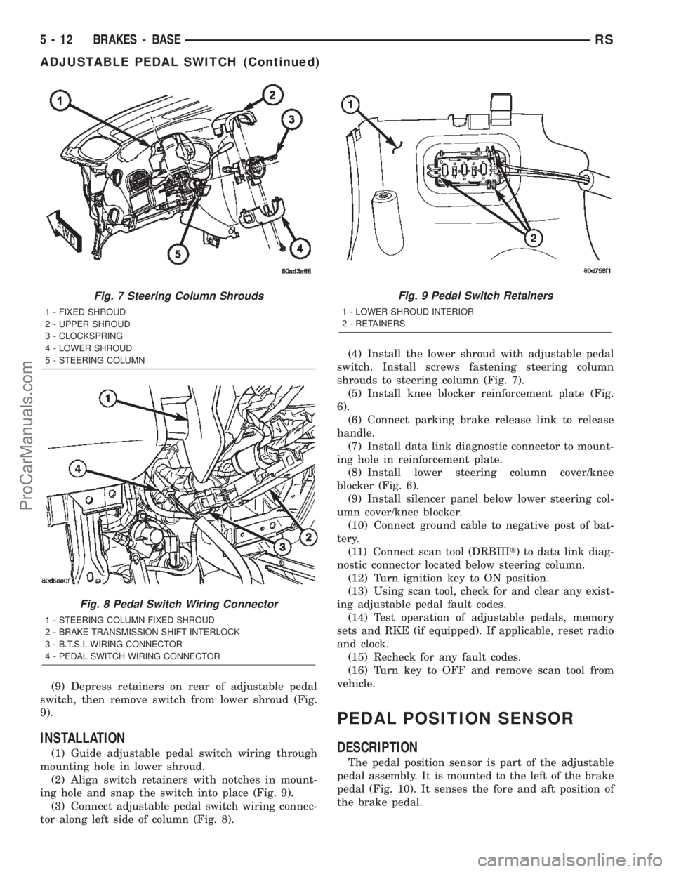
(9) Depress retainers on rear of adjustable pedal
switch, then remove switch from lower shroud (Fig.
9).
INSTALLATION
(1) Guide adjustable pedal switch wiring through
mounting hole in lower shroud.
(2) Align switch retainers with notches in mount-
ing hole and snap the switch into place (Fig. 9).
(3) Connect adjustable pedal switch wiring connec-
tor along left side of column (Fig. 8).(4) Install the lower shroud with adjustable pedal
switch. Install screws fastening steering column
shrouds to steering column (Fig. 7).
(5) Install knee blocker reinforcement plate (Fig.
6).
(6) Connect parking brake release link to release
handle.
(7) Install data link diagnostic connector to mount-
ing hole in reinforcement plate.
(8) Install lower steering column cover/knee
blocker (Fig. 6).
(9) Install silencer panel below lower steering col-
umn cover/knee blocker.
(10) Connect ground cable to negative post of bat-
tery.
(11) Connect scan tool (DRBIIIt) to data link diag-
nostic connector located below steering column.
(12) Turn ignition key to ON position.
(13) Using scan tool, check for and clear any exist-
ing adjustable pedal fault codes.
(14) Test operation of adjustable pedals, memory
sets and RKE (if equipped). If applicable, reset radio
and clock.
(15) Recheck for any fault codes.
(16) Turn key to OFF and remove scan tool from
vehicle.
PEDAL POSITION SENSOR
DESCRIPTION
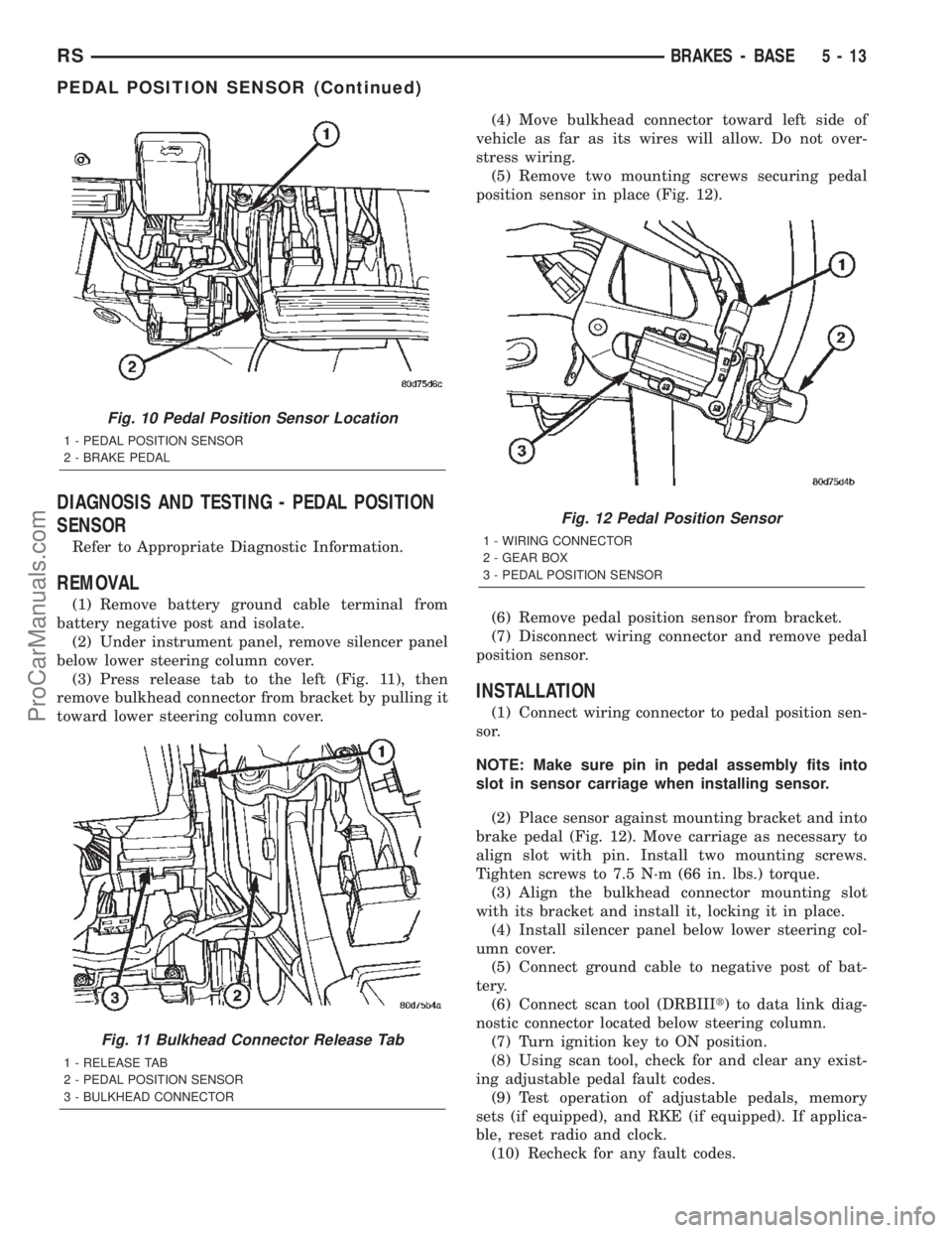
The pedal position sensor is part of the adjustable
pedal assembly. It is mounted to the left of the brake
pedal (Fig. 10). It senses the fore and aft position of
the brake pedal.
Fig. 7 Steering Column Shrouds
1 - FIXED SHROUD
2 - UPPER SHROUD
3 - CLOCKSPRING
4 - LOWER SHROUD
5 - STEERING COLUMN
Fig. 8 Pedal Switch Wiring Connector
1 - STEERING COLUMN FIXED SHROUD
2 - BRAKE TRANSMISSION SHIFT INTERLOCK
3 - B.T.S.I. WIRING CONNECTOR
4 - PEDAL SWITCH WIRING CONNECTOR
Fig. 9 Pedal Switch Retainers
1 - LOWER SHROUD INTERIOR
2 - RETAINERS
5 - 12 BRAKES - BASERS
ADJUSTABLE PEDAL SWITCH (Continued)
ProCarManuals.com
Page 142 of 2399
DIAGNOSIS AND TESTING - PEDAL POSITION
SENSOR
Refer to Appropriate Diagnostic Information.
REMOVAL
(1) Remove battery ground cable terminal from
battery negative post and isolate.
(2) Under instrument panel, remove silencer panel
below lower steering column cover.
(3) Press release tab to the left (Fig. 11), then
remove bulkhead connector from bracket by pulling it
toward lower steering column cover.(4) Move bulkhead connector toward left side of
vehicle as far as its wires will allow. Do not over-
stress wiring.
(5) Remove two mounting screws securing pedal
position sensor in place (Fig. 12).
(6) Remove pedal position sensor from bracket.
(7) Disconnect wiring connector and remove pedal
position sensor.
INSTALLATION
(1) Connect wiring connector to pedal position sen-
sor.
NOTE: Make sure pin in pedal assembly fits into
slot in sensor carriage when installing sensor.
(2) Place sensor against mounting bracket and into
brake pedal (Fig. 12). Move carriage as necessary to
align slot with pin. Install two mounting screws.
Tighten screws to 7.5 N´m (66 in. lbs.) torque.
(3) Align the bulkhead connector mounting slot
with its bracket and install it, locking it in place.
(4) Install silencer panel below lower steering col-
umn cover.
(5) Connect ground cable to negative post of bat-
tery.
(6) Connect scan tool (DRBIIIt) to data link diag-
nostic connector located below steering column.
(7) Turn ignition key to ON position.
(8) Using scan tool, check for and clear any exist-
ing adjustable pedal fault codes.
(9) Test operation of adjustable pedals, memory
sets (if equipped), and RKE (if equipped). If applica-
ble, reset radio and clock.
(10) Recheck for any fault codes.
Fig. 10 Pedal Position Sensor Location
1 - PEDAL POSITION SENSOR
2 - BRAKE PEDAL
Fig. 11 Bulkhead Connector Release Tab
1 - RELEASE TAB
2 - PEDAL POSITION SENSOR
3 - BULKHEAD CONNECTOR
Fig. 12 Pedal Position Sensor
1 - WIRING CONNECTOR
2 - GEAR BOX
3 - PEDAL POSITION SENSOR
RSBRAKES - BASE5-13
PEDAL POSITION SENSOR (Continued)
ProCarManuals.com
Page 176 of 2399
(27) Install lower steering column cover/knee
blocker (Fig. 62).
(28) Install silencer panel below lower steering col-
umn cover/knee blocker.
NOTE: When reconnecting the battery on a vehicle
that has had the airbag module removed, the fol-
lowing procedure should be used.
(29) Reconnect ground cable to negative post of
battery in following manor:
(a) Connect scan tool (DRBIIIt) to data link
diagnostic connector located below steering column.
(b) Turn ignition key to ON position. Exit vehi-
cle with scan tool leaving scan tool harness
plugged in.
(c) Ensuring that there are no occupants in vehi-
cle, connect ground (-) cable to the negative post of
the battery.
(d) Using scan tool, read and record any airbag
fault codes. Refer to Appropriate Diagnostic Infor-
mation if any faults are found.
(e) Through drivers open window, Reach around
back of steering wheel (between steering wheel and
instrument cluster) and turn ignition key to OFF,
then back ON while observing instrument cluster
airbag indicator lamp. It should go on for six to
eight seconds, then go out. This action indicates
that airbag system is functioning normally. If air-
bag indicator lamp fails to light, blinks on and off,
or goes on and stays on, there is an airbag system
malfunction. Refer to Appropriate Diagnostic Infor-
mation to diagnose the system malfunction.
(30) Using scan tool (DRBIIIt), check for and clear
any existing adjustable pedal fault codes. The adjust-
able pedal system is now activated.
(31) Turn key to OFF and remove scan tool from
vehicle.
(32) Test operation of adjustable pedals, memory
seats (if equipped), RKE (if equipped), and all func-
tions that are steering column operated. If applica-
ble, reset the radio and the clock.
(33) Road test the vehicle to ensure proper opera-
tion of the steering and brake systems.
PEDAL TORQUE SHAFT - RHD
REMOVAL
(1) Remove the instrument panel. (Refer to 23 -
BODY/INSTRUMENT PANEL/INSTRUMENT
PANEL ASSEMBLY - REMOVAL)
(2) Remove the HVAC housing. (Refer to 24 -
HEATING & AIR CONDITIONING/DISTRIBUTION/
HVAC HOUSING - REMOVAL)
(3) Remove the retaining clip at the torque shaft
end of the brake pedal-to-torque shaft link. Removethe link from the torque shaft. Discard the retaining
clip. It is not to be reused. Replace with a new clip
when reassembled.
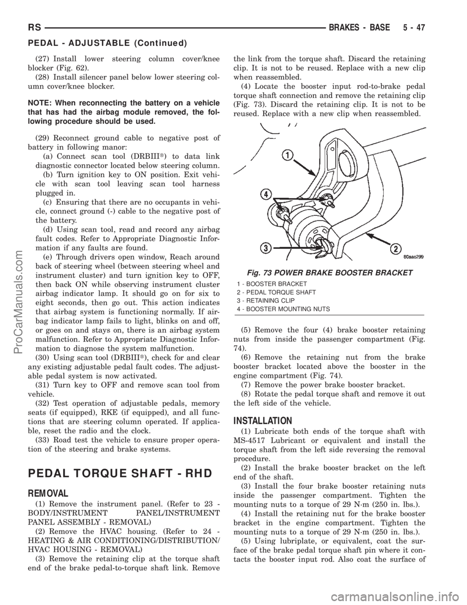
(4) Locate the booster input rod-to-brake pedal
torque shaft connection and remove the retaining clip
(Fig. 73). Discard the retaining clip. It is not to be
reused. Replace with a new clip when reassembled.
(5) Remove the four (4) brake booster retaining
nuts from inside the passenger compartment (Fig.
74).
(6) Remove the retaining nut from the brake
booster bracket located above the booster in the
engine compartment (Fig. 74).
(7) Remove the power brake booster bracket.
(8) Rotate the pedal torque shaft and remove it out
the left side of the vehicle.
INSTALLATION
(1) Lubricate both ends of the torque shaft with
MS-4517 Lubricant or equivalent and install the
torque shaft from the left side reversing the removal
procedure.
(2) Install the brake booster bracket on the left
end of the shaft.
(3) Install the four brake booster retaining nuts
inside the passenger compartment. Tighten the
mounting nuts to a torque of 29 N´m (250 in. lbs.).
(4) Install the retaining nut for the brake booster
bracket in the engine compartment. Tighten the
mounting nuts to a torque of 29 N´m (250 in. lbs.).
(5) Using lubriplate, or equivalent, coat the sur-
face of the brake pedal torque shaft pin where it con-
tacts the booster input rod. Also coat the surface of
Fig. 73 POWER BRAKE BOOSTER BRACKET
1 - BOOSTER BRACKET
2 - PEDAL TORQUE SHAFT
3 - RETAINING CLIP
4 - BOOSTER MOUNTING NUTS
RSBRAKES - BASE5-47
PEDAL - ADJUSTABLE (Continued)
ProCarManuals.com
Page 217 of 2399
ªthermo-protection mode,º the traction control func-
tion lamp illuminates TRAC OFF; note that no trou-
ble code is registered.
CAUTION
CAUTIONS
The ABS uses an electronic control module, the
CAB. This module is designed to withstand normal
current draws associated with vehicle operation.
Care must be taken to avoid overloading the CAB
circuits.
CAUTION: In testing for open or short circuits, do
not ground or apply voltage to any of the circuits
unless instructed to do so for a diagnostic proce-
dure.
CAUTION: These circuits should only be tested
using a high impedance multi-meter or the DRBIIIT
scan tool as described in this section. Power
should never be removed or applied to any control
module with the ignition in the ON position. Before
removing or connecting battery cables, fuses, or
connectors, always turn the ignition to the OFF
position.
CAUTION: The CAB 24-way connector should never
be connected or disconnected with the ignition
switch in the ON position.
CAUTION: This vehicle utilizes active wheel speed
sensors. Do not apply voltage to wheel speed sen-
sors at any time.
CAUTION: Use only factory wiring harnesses. Do
not cut or splice wiring to the brake circuits. The
addition of aftermarket electrical equipment (car
phone, radar detector, citizen band radio, trailer
lighting, trailer brakes, etc.) on a vehicle equipped
with antilock brakes may affect the function of the
antilock brake system.
CAUTION: When performing any service procedure
on a vehicle equipped with ABS, do not apply a
12-volt power source to the ground circuit of the
pump motor in the HCU. Doing this will damage the
pump motor and will require replacement of the
entire HCU.CAUTION: An attempt to remove or disconnect cer-
tain system components may result in improper
system operation. Only those components with
approved removal and installation procedures in
this manual should be serviced.
CAUTION: If welding work is to be performed on the
vehicle, using an electric arc welder, the CAB con-
nector should be disconnected during the welding
operation.
CAUTION: Many components of the ABS System
are not serviceable and must be replaced as an
assembly. Do not disassemble any component
which is not designed to be serviced.
CAUTION: Only the recommended jacking or hoist-
ing positions for this vehicle are to be used when-
ever it is necessary to lift a vehicle. Failure to raise
a vehicle from the recommended locations could
result in lifting a vehicle by the hydraulic control
unit mounting bracket. Lifting a vehicle by the
hydraulic control unit mounting bracket will result
in damage to the mounting bracket and the hydrau-
lic control unit.
CAUTION: Brake fluid will damage painted surfaces.
If brake fluid is spilled on any painted surface,
wash off with water immediately.
STANDARD PROCEDURE - ANTILOCK BRAKE
SYSTEM BLEEDING
The base brake's hydraulic system must be bled
anytime air enters the hydraulic system. The ABS
though, particularly the ICU (HCU), should only be
bled when the HCU is replaced or removed from the
vehicle. The ABS must always be bled anytime it is
suspected that the HCU has ingested air. Under
most circumstances that require the bleeding of the
brakes hydraulic system, only the base brake
hydraulic system needs to be bled.
It is important to note that excessive air in the
brake system will cause a soft or spongy feeling
brake pedal.
During the brake bleeding procedure, be sure the
brake fluid level remains close to the FULL level in
the master cylinder fluid reservoir. Check the fluid
level periodically during the bleeding procedure and
add DOT 3 brake fluid as required.
The ABS must be bled as two independent braking
systems. The non-ABS portion of the brake system
with ABS is to be bled the same as any non-ABS sys-
tem.
5 - 88 BRAKES - ABSRS
BRAKES - ABS (Continued)
ProCarManuals.com
Page 320 of 2399

AUDIO
TABLE OF CONTENTS
page page
AUDIO
DESCRIPTION..........................1
OPERATION............................1
DIAGNOSIS AND TESTING - AUDIO..........1
ANTENNA BODY AND CABLE
DESCRIPTION..........................4
OPERATION............................4
DIAGNOSIS AND TESTING - ANTENNA BODY
AND CABLE..........................4
REMOVAL.............................4
INSTALLATION..........................5
ANTENNA MODULE - EXPORT
DESCRIPTION..........................6
OPERATION............................6
DIAGNOSIS AND TESTING - ANTENNA
MODULE - EXPORT....................6
REMOVAL.............................7
INSTALLATION..........................7
CD CHANGER
DESCRIPTION..........................7
OPERATION............................7
REMOVAL.............................7
INSTALLATION..........................7
INSTRUMENT PANEL ANTENNA CABLE
REMOVAL.............................8INSTALLATION..........................8
QUARTER GLASS INTEGRAL ANTENNA -
EXPORT
DESCRIPTION..........................8
OPERATION............................8
DIAGNOSIS AND TESTING - QUARTER
GLASS INTEGRAL ANTENNA - EXPORT.....8
RADIO
DIAGNOSIS AND TESTING - RADIO..........9
REMOVAL.............................9
INSTALLATION.........................10
RADIO NOISE SUPPRESSION COMPONENTS
DESCRIPTION.........................10
OPERATION...........................10
REMOTE SWITCHES
DESCRIPTION.........................11
OPERATION...........................11
DIAGNOSIS AND TESTING - REMOTE
SWITCHES..........................11
REMOVAL.............................12
INSTALLATION.........................12
SPEAKER
DIAGNOSIS AND TESTING - SPEAKER......12
REMOVAL.............................13
INSTALLATION.........................14
AUDIO
DESCRIPTION
There are four different system combinations avail-
able on this model. The available radio options are:
²AM/FM Cassette
²AM/FM Compact Disc with Compact Disc
changer controls
²AM/FM Cassette with single Compact Disc
Player and Compact Disc changer controls
²AM/FM Cassette with Compact Disc changer
controls
²AM/FM Cassette with Compact Disc player, rear
seat audio system and Compact Disc changer con-
trols.
The rear seat audio system allows passengers to
listen to a different music source, through head-
phones, other than what is playing through the vehi-
cles speaker system. A remote control is provided for
functions such as changing stations, tracks, disc and
modes while listening to rear seat audio. The radiomust be turned ON to use the rear seat audio sys-
tem.
All factory installed radio receivers are stereo Elec-
tronically Tuned Radios (ETR) and include and elec-
tronic digital clock function.
OPERATION
Operating instructions for the factory installed
audio systems can be found in the Owner's Manual
provided with this vehicle.
DIAGNOSIS AND TESTING - AUDIO
Any diagnosis of the Audio system should
begin with the use of the DRB IIItdiagnostic
tool. For information on the use of the DRB
IIIt, refer to the appropriate Diagnostic Service
Manual.
Refer to the appropriate wiring information. The
wiring information includes wiring diagrams, proper
wire and connector repair procedures, details of wire
harness routing and retention, connector pin-out
RSAUDIO8A-1
ProCarManuals.com
Page 321 of 2399
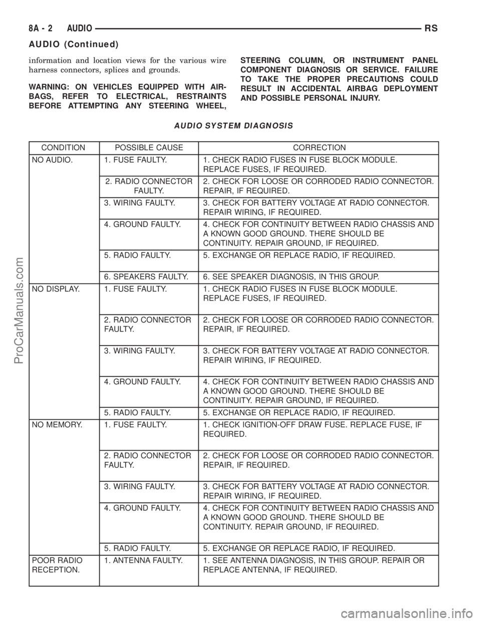
information and location views for the various wire
harness connectors, splices and grounds.
WARNING: ON VEHICLES EQUIPPED WITH AIR-
BAGS, REFER TO ELECTRICAL, RESTRAINTS
BEFORE ATTEMPTING ANY STEERING WHEEL,STEERING COLUMN, OR INSTRUMENT PANEL
COMPONENT DIAGNOSIS OR SERVICE. FAILURE
TO TAKE THE PROPER PRECAUTIONS COULD
RESULT IN ACCIDENTAL AIRBAG DEPLOYMENT
AND POSSIBLE PERSONAL INJURY.
AUDIO SYSTEM DIAGNOSIS
CONDITION POSSIBLE CAUSE CORRECTION
NO AUDIO. 1. FUSE FAULTY. 1. CHECK RADIO FUSES IN FUSE BLOCK MODULE.
REPLACE FUSES, IF REQUIRED.
2. RADIO CONNECTOR
FAULTY.2. CHECK FOR LOOSE OR CORRODED RADIO CONNECTOR.
REPAIR, IF REQUIRED.
3. WIRING FAULTY. 3. CHECK FOR BATTERY VOLTAGE AT RADIO CONNECTOR.
REPAIR WIRING, IF REQUIRED.
4. GROUND FAULTY. 4. CHECK FOR CONTINUITY BETWEEN RADIO CHASSIS AND
A KNOWN GOOD GROUND. THERE SHOULD BE
CONTINUITY. REPAIR GROUND, IF REQUIRED.
5. RADIO FAULTY. 5. EXCHANGE OR REPLACE RADIO, IF REQUIRED.
6. SPEAKERS FAULTY. 6. SEE SPEAKER DIAGNOSIS, IN THIS GROUP.
NO DISPLAY. 1. FUSE FAULTY. 1. CHECK RADIO FUSES IN FUSE BLOCK MODULE.
REPLACE FUSES, IF REQUIRED.
2. RADIO CONNECTOR
FAULTY.2. CHECK FOR LOOSE OR CORRODED RADIO CONNECTOR.
REPAIR, IF REQUIRED.
3. WIRING FAULTY. 3. CHECK FOR BATTERY VOLTAGE AT RADIO CONNECTOR.
REPAIR WIRING, IF REQUIRED.
4. GROUND FAULTY. 4. CHECK FOR CONTINUITY BETWEEN RADIO CHASSIS AND
A KNOWN GOOD GROUND. THERE SHOULD BE
CONTINUITY. REPAIR GROUND, IF REQUIRED.
5. RADIO FAULTY. 5. EXCHANGE OR REPLACE RADIO, IF REQUIRED.
NO MEMORY. 1. FUSE FAULTY. 1. CHECK IGNITION-OFF DRAW FUSE. REPLACE FUSE, IF
REQUIRED.
2. RADIO CONNECTOR
FAULTY.2. CHECK FOR LOOSE OR CORRODED RADIO CONNECTOR.
REPAIR, IF REQUIRED.
3. WIRING FAULTY. 3. CHECK FOR BATTERY VOLTAGE AT RADIO CONNECTOR.
REPAIR WIRING, IF REQUIRED.
4. GROUND FAULTY. 4. CHECK FOR CONTINUITY BETWEEN RADIO CHASSIS AND
A KNOWN GOOD GROUND. THERE SHOULD BE
CONTINUITY. REPAIR GROUND, IF REQUIRED.
5. RADIO FAULTY. 5. EXCHANGE OR REPLACE RADIO, IF REQUIRED.
POOR RADIO
RECEPTION.1. ANTENNA FAULTY. 1. SEE ANTENNA DIAGNOSIS, IN THIS GROUP. REPAIR OR
REPLACE ANTENNA, IF REQUIRED.
8A - 2 AUDIORS
AUDIO (Continued)
ProCarManuals.com
Page 322 of 2399

CONDITION POSSIBLE CAUSE CORRECTION
2. GROUND FAULTY. 2. CHECK FOR CONTINUITY BETWEEN RADIO CHASSIS AND
A KNOWN GOOD GROUND. THERE SHOULD BE
CONTINUITY. REPAIR GROUND, IF REQUIRED.
3. RADIO FAULTY. 3. EXCHANGE OR REPLACE RADIO, IF REQUIRED.
4. POOR ANTENNA
CONNECTION AT
RADIO OR IN LINE.4. SEAT CONNECTOR.
NO/POOR TAPE
OPERATION.1. FAULTY TAPE. 1. INSERT KNOWN GOOD TAPE AND TEST OPERATION.
2. FOREIGN OBJECTS
BEHIND TAPE DOOR.2. REMOVE FOREIGN OBJECTS AND TEST OPERATION.
3. DIRTY CASSETTE
TAPE HEAD.3. CLEAN HEAD WITH MOPAR CASSETTE HEAD CLEANER.
4. FAULTY TAPE DECK. 4. EXCHANGE OR REPLACE RADIO, IF REQUIRED.
NO COMPACT
DISC
OPERATION1. FAULTY CD. 1. INSERT KNOWN GOOD CD AND TEST OPERATION.
2. FOREIGN MATERIAL
ON CD.2. CLEAN CD AND TEST OPERATION.
3. CONDENSATION ON
CD OR OPTICS.3. ALLOW TEMPERATURE OF VEHICLE INTERIOR TO
STABILIZE AND TEST OPERATION.
4. FAULTY CD PLAYER. 4. EXCHANGE OR REPLACE RADIO, IF REQUIRED.
HEADPHONES
WILL NOT HOLD
A CHANNEL OR
HAVE STATIC1. WEAK BATTERIES IN
THE HEADPHONES.1. REPLACE BATTERIES.
2. CLOSENESS TO
RADIO TRANSMITTER
SUCH AS A RADIO
TOWER, AIRPORT
TRANSMITTER OR
SOME MOBILE
RADIOS.2. MOVE TO AN AREA AWAY FREE FROM THESE
CONDITIONS.
REMOTE
CONTROL
INOPERATIVE1. WEAK BATTERIES IN
THE REMOTE
CONTROL.1. REPLACE BATTERIES.
2. OPERATION
CONSTRAINT OF
SYSTEM2. MAKE SURE THAT REAR AUDIO IS IN A DIFFERENT MODE
THAN FRONT SPEAKERS. REMOTE CONTROL WILL NOT
WORK WHEN BOTH ARE IN THE SAME MODE.
RSAUDIO8A-3
AUDIO (Continued)
ProCarManuals.com
Page 323 of 2399
ANTENNA BODY AND CABLE
DESCRIPTION
All models use a fixed-length stainless steel rod-
type antenna mast, installed at the right front fender
of the vehicle. The antenna mast is connected to the
center wire of the coaxial antenna cable, and is not
grounded to any part of the vehicle.
OPERATION
To minimize static, the antenna base must have a
good ground. The coaxial antenna cable shield (the
outer wire mesh of the cable) is grounded to the
antenna base and the radio chassis.
The antenna coaxial cable has an additional dis-
connect, located near the right end of the instrument
panel. This additional disconnect allows the instru-
ment panel assembly to be removed and installed
without removing the radio.
The factory-installed Electronically Tuned Radios
(ETRs) automatically compensate for radio antenna
trim. Therefore, no antenna trimmer adjustment is
required or possible when replacing the receiver or
the antenna.
DIAGNOSIS AND TESTING - ANTENNA BODY
AND CABLE
WARNING: ON VEHICLES EQUIPPED WITH AIR-
BAGS, REFER TO ELECTRICAL, RESTRAINTS
BEFORE ATTEMPTING ANY STEERING WHEEL,
STEERING COLUMN, OR INSTRUMENT PANEL
COMPONENT DIAGNOSIS OR SERVICE. FAILURE
TO TAKE THE PROPER PRECAUTIONS COULD
RESULT IN ACCIDENTAL AIRBAG DEPLOYMENT
AND POSSIBLE PERSONAL INJURY.
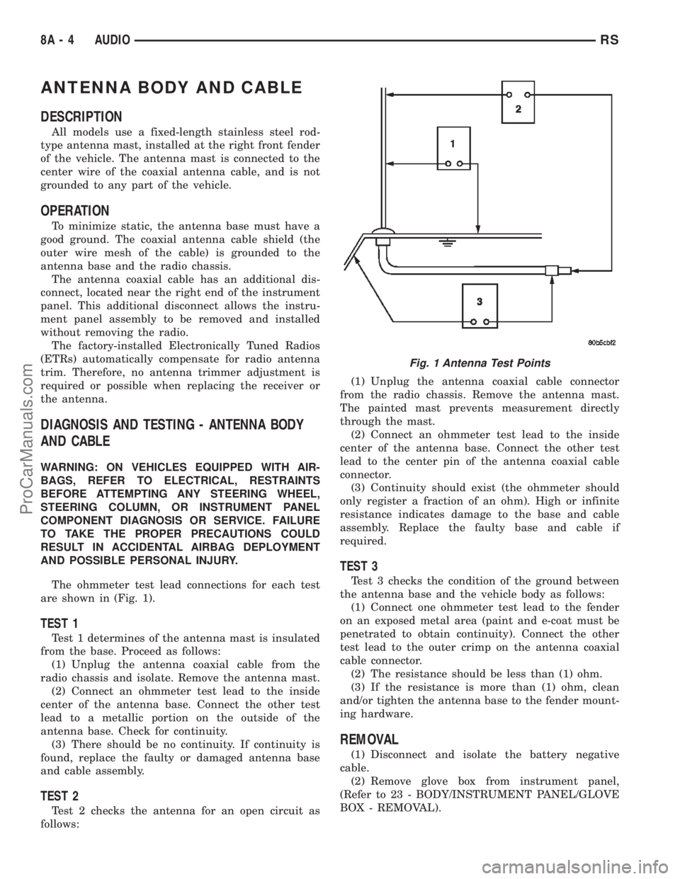
The ohmmeter test lead connections for each test
are shown in (Fig. 1).
TEST 1
Test 1 determines of the antenna mast is insulated
from the base. Proceed as follows:
(1) Unplug the antenna coaxial cable from the
radio chassis and isolate. Remove the antenna mast.
(2) Connect an ohmmeter test lead to the inside
center of the antenna base. Connect the other test
lead to a metallic portion on the outside of the
antenna base. Check for continuity.
(3) There should be no continuity. If continuity is
found, replace the faulty or damaged antenna base
and cable assembly.
TEST 2
Test 2 checks the antenna for an open circuit as
follows:(1) Unplug the antenna coaxial cable connector
from the radio chassis. Remove the antenna mast.
The painted mast prevents measurement directly
through the mast.
(2) Connect an ohmmeter test lead to the inside
center of the antenna base. Connect the other test
lead to the center pin of the antenna coaxial cable
connector.
(3) Continuity should exist (the ohmmeter should
only register a fraction of an ohm). High or infinite
resistance indicates damage to the base and cable
assembly. Replace the faulty base and cable if
required.
TEST 3
Test 3 checks the condition of the ground between
the antenna base and the vehicle body as follows:
(1) Connect one ohmmeter test lead to the fender
on an exposed metal area (paint and e-coat must be
penetrated to obtain continuity). Connect the other
test lead to the outer crimp on the antenna coaxial
cable connector.
(2) The resistance should be less than (1) ohm.
(3) If the resistance is more than (1) ohm, clean
and/or tighten the antenna base to the fender mount-
ing hardware.
REMOVAL
(1) Disconnect and isolate the battery negative
cable.
(2) Remove glove box from instrument panel,
(Refer to 23 - BODY/INSTRUMENT PANEL/GLOVE
BOX - REMOVAL).
Fig. 1 Antenna Test Points
8A - 4 AUDIORS
ProCarManuals.com
Page 324 of 2399
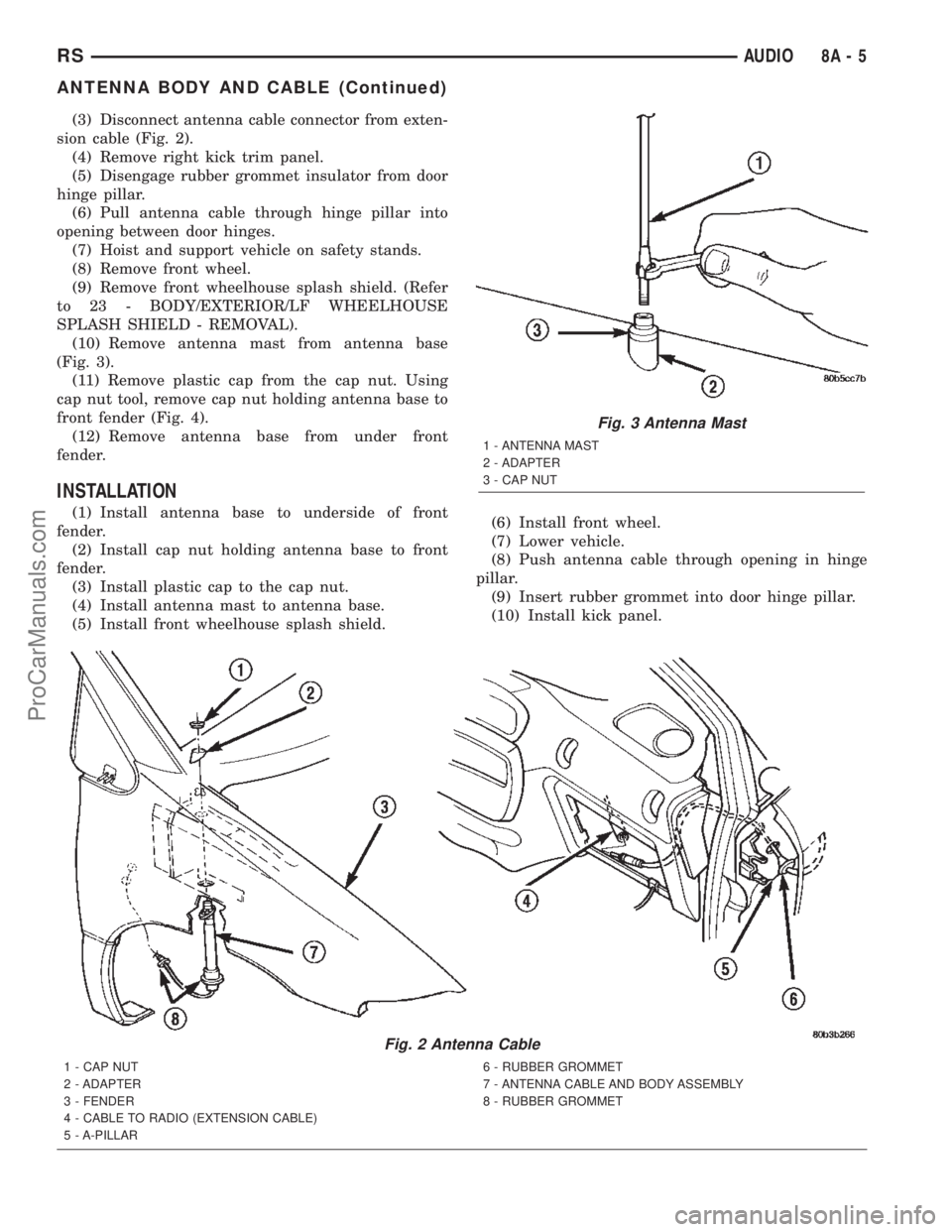
(3) Disconnect antenna cable connector from exten-
sion cable (Fig. 2).
(4) Remove right kick trim panel.
(5) Disengage rubber grommet insulator from door
hinge pillar.
(6) Pull antenna cable through hinge pillar into
opening between door hinges.
(7) Hoist and support vehicle on safety stands.
(8) Remove front wheel.
(9) Remove front wheelhouse splash shield. (Refer
to 23 - BODY/EXTERIOR/LF WHEELHOUSE
SPLASH SHIELD - REMOVAL).
(10) Remove antenna mast from antenna base
(Fig. 3).
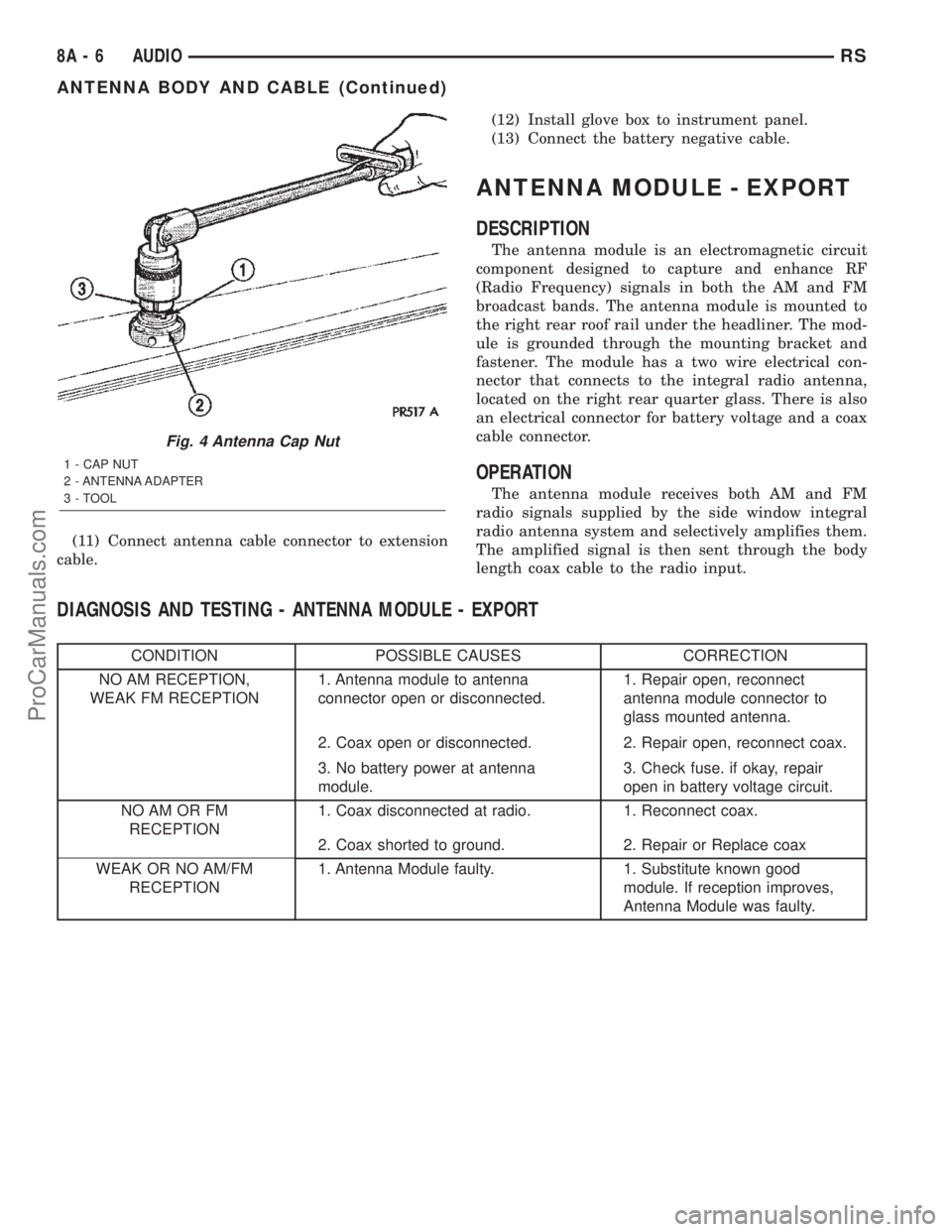
(11) Remove plastic cap from the cap nut. Using
cap nut tool, remove cap nut holding antenna base to
front fender (Fig. 4).
(12) Remove antenna base from under front
fender.
INSTALLATION
(1) Install antenna base to underside of front
fender.
(2) Install cap nut holding antenna base to front
fender.
(3) Install plastic cap to the cap nut.
(4) Install antenna mast to antenna base.
(5) Install front wheelhouse splash shield.(6) Install front wheel.
(7) Lower vehicle.
(8) Push antenna cable through opening in hinge
pillar.
(9) Insert rubber grommet into door hinge pillar.
(10) Install kick panel.
Fig. 2 Antenna Cable
1 - CAP NUT
2 - ADAPTER
3 - FENDER
4 - CABLE TO RADIO (EXTENSION CABLE)
5 - A-PILLAR6 - RUBBER GROMMET
7 - ANTENNA CABLE AND BODY ASSEMBLY
8 - RUBBER GROMMET
Fig. 3 Antenna Mast
1 - ANTENNA MAST
2 - ADAPTER
3 - CAP NUT
RSAUDIO8A-5
ANTENNA BODY AND CABLE (Continued)
ProCarManuals.com
Page 325 of 2399
(11) Connect antenna cable connector to extension
cable.(12) Install glove box to instrument panel.
(13) Connect the battery negative cable.
ANTENNA MODULE - EXPORT
DESCRIPTION
The antenna module is an electromagnetic circuit
component designed to capture and enhance RF
(Radio Frequency) signals in both the AM and FM
broadcast bands. The antenna module is mounted to
the right rear roof rail under the headliner. The mod-
ule is grounded through the mounting bracket and
fastener. The module has a two wire electrical con-
nector that connects to the integral radio antenna,
located on the right rear quarter glass. There is also
an electrical connector for battery voltage and a coax
cable connector.
OPERATION
The antenna module receives both AM and FM
radio signals supplied by the side window integral
radio antenna system and selectively amplifies them.
The amplified signal is then sent through the body
length coax cable to the radio input.
DIAGNOSIS AND TESTING - ANTENNA MODULE - EXPORT
CONDITION POSSIBLE CAUSES CORRECTION
NO AM RECEPTION,
WEAK FM RECEPTION1. Antenna module to antenna
connector open or disconnected.1. Repair open, reconnect
antenna module connector to
glass mounted antenna.
2. Coax open or disconnected. 2. Repair open, reconnect coax.
3. No battery power at antenna
module.3. Check fuse. if okay, repair
open in battery voltage circuit.
NO AM OR FM
RECEPTION1. Coax disconnected at radio. 1. Reconnect coax.
2. Coax shorted to ground. 2. Repair or Replace coax
WEAK OR NO AM/FM
RECEPTION1. Antenna Module faulty. 1. Substitute known good
module. If reception improves,
Antenna Module was faulty.
Fig. 4 Antenna Cap Nut
1 - CAP NUT
2 - ANTENNA ADAPTER
3 - TOOL
8A - 6 AUDIORS
ANTENNA BODY AND CABLE (Continued)
ProCarManuals.com