weight CHRYSLER CARAVAN 2003 User Guide
[x] Cancel search | Manufacturer: CHRYSLER, Model Year: 2003, Model line: CARAVAN, Model: CHRYSLER CARAVAN 2003Pages: 2177, PDF Size: 59.81 MB
Page 88 of 2177
(2) Remove the nut and bolt attaching the track
bar to the track bar mount on the body of the vehicle.
Remove the track bar from the track bar mount.
INSTALLATION
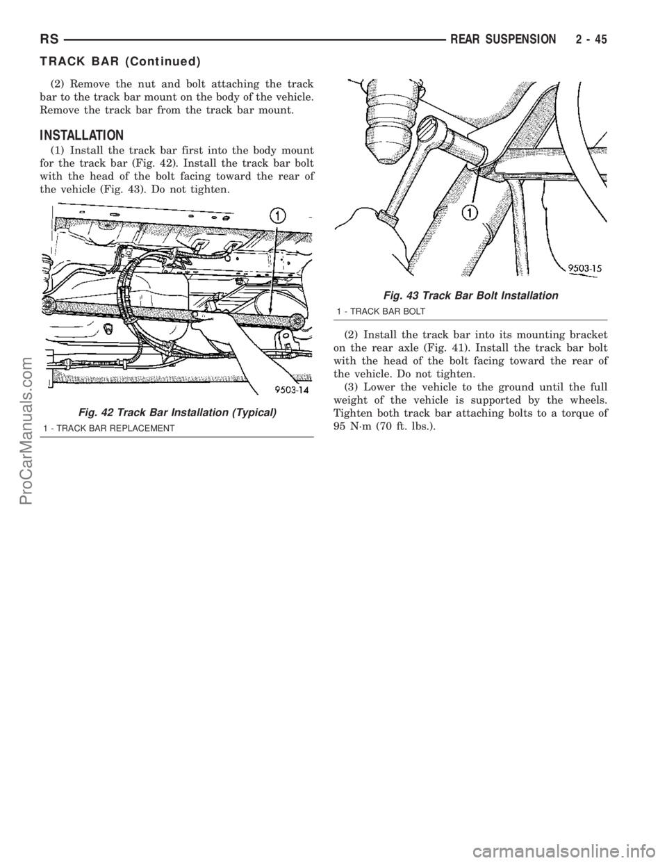
(1) Install the track bar first into the body mount
for the track bar (Fig. 42). Install the track bar bolt
with the head of the bolt facing toward the rear of
the vehicle (Fig. 43). Do not tighten.
(2) Install the track bar into its mounting bracket
on the rear axle (Fig. 41). Install the track bar bolt
with the head of the bolt facing toward the rear of
the vehicle. Do not tighten.
(3) Lower the vehicle to the ground until the full
weight of the vehicle is supported by the wheels.
Tighten both track bar attaching bolts to a torque of
95 N´m (70 ft. lbs.).
Fig. 42 Track Bar Installation (Typical)
1 - TRACK BAR REPLACEMENT
Fig. 43 Track Bar Bolt Installation
1 - TRACK BAR BOLT
RSREAR SUSPENSION2-45
TRACK BAR (Continued)
ProCarManuals.com
Page 94 of 2177
CONDITION POSSIBLE CAUSES CORRECTION
Excessive Steering Effort 1. Low tire pressure 1. Inflate all tires to recommended
pressure
2. Lack of lubricant in steering gear 2. Replace steering gear
3. Low power steering fluid level 3. Fill power steering fluid reservoir to
correct level
4. Loose power steering pump drive
belt4. Correctly adjust power steering pump
drive belt
5. Lack of lubricant in ball joints 5. Lubricate or replace ball joints
6. Steering gear malfunction 6. Replace steering gear
7. Lack of lubricant in steering coupler 7. Replace steering coupler
STANDARD PROCEDURE
STANDARD PROCEDURE - WHEEL ALIGNMENT
PRE-WHEEL ALIGNMENT INSPECTION
Before any attempt is made to change or correct
the wheel alignment, the following inspection and
necessary corrections must be made to ensure proper
alignment.
(1) Verify that the fuel tank is full of fuel. If the
tank is not full, the reduction in weight will affect
the curb height of the vehicle and the alignment
angles.
(2) The passenger and luggage compartments of
the vehicle should be free of any load that is not fac-
tory equipment.
(3) Check the tires on the vehicle. All tires must be
the same size and in good condition with approxi-
mately the same amount of tread wear. Inflate all
the tires to the recommended air pressure.
(4) Check the front wheel and tire assemblies for
excessive radial runout.
(5) Inspect lower ball joints and all steering link-
age for looseness, binding, wear or damage. Repair as
necessary.
(6) Check suspension fasteners for proper torque
and retighten as necessary.
(7) Inspect all suspension component rubber bush-
ings for signs of wear or deterioration. Replace any
faulty bushings or components before aligning the
vehicle.
(8) Check the vehicle's curb height to verify it is
within specifications. Refer to Curb Height Measure-
ment.
WHEEL ALIGNMENT SETUP
(1) Position the vehicle on an alignment rack.
(2) Install all required alignment equipment on
the vehicle per the alignment equipment manufactur-
er's instructions. On this vehicle, a four-wheel align-
ment is recommended.NOTE: Prior to reading the vehicle's alignment
readouts, the front and rear of vehicle should be
jounced. Induce jounce (rear first, then front) by
grasping the center of the bumper and jouncing
each end of vehicle an equal number of times. The
bumper should always be released when vehicle is
at the bottom of the jounce cycle.
(3) Read the vehicle's current front and rear align-
ment settings. Compare the vehicle's current align-
ment settings to the vehicle specifications for camber,
caster and toe-in. (Refer to 2 - SUSPENSION/
WHEEL ALIGNMENT - SPECIFICATIONS)
(4) If front camber and caster are not within spec-
ifications, proceed to CAMBER AND CASTER below.
If caster and camber are within specifications, pro-
ceed to TOE which can be found following CAMBER
AND CASTER. Rear camber, caster and toe are not
adjustable. If found not to be within specifications,
reinspect for damaged suspension or body compo-
nents and replace as necessary.
CAMBER AND CASTER
Camber and caster settings on this vehicle are
determined at the time the vehicle is designed, by
the location of the vehicle's suspension components.
This is referred to as NET BUILD. The result is no
required adjustment of camber and caster after the
vehicle is built or when servicing the suspension
components. Thus, when performing a wheel align-
ment, caster and camber are not normally considered
adjustable angles. Camber and caster should be
checked to ensure they meet vehicle specifications.
If front camber is found not to meet alignment
specifications, it can be adjusted using an available
camber adjustment bolt package. Before installing a
camber adjustment bolt package on a vehicle found
to be outside the specifications, inspect the suspen-
sion components for any signs of damage or bending.
RSWHEEL ALIGNMENT2-51
WHEEL ALIGNMENT (Continued)
ProCarManuals.com
Page 95 of 2177
CAUTION: Do not attempt to adjust the vehicles
wheel alignment by heating, bending or by perform-
ing any other modification to the vehicle's front
suspension components or body.
If camber readings are not within specifications,
use the following procedure to install the front cam-
ber adjustment bolt package and then adjust front
camber.
CAMBER ADJUSTMENT BOLT PACKAGE INSTALLATION
The camber adjustment bolt package contains 2
flange bolts, 2 cam bolts, 2 dog bone washers, and 4
nuts. This package services both sides of the vehicle.
Use the package to attach the strut clevis bracket to
the steering knuckle after the strut clevis bracket
has been modified. To install and adjust the camber
adjustment bolt package, follow the procedure below.
(1) Raise the vehicle until its tires are not support-
ing the weight of the vehicle.
(2) Remove the front tire and wheel assemblies.
CAUTION: When removing the steering knuckle
from the strut clevis bracket, do not put a strain on
the brake flex hose. Also, do not let the weight of
the steering knuckle assembly be supported by the
brake flex hose when removed from the strut
assembly. If necessary use a wire hanger to sup-
port the steering knuckle assembly or if required
remove the brake flex hose from the caliper assem-
bly.
CAUTION: The knuckle to strut assembly attaching
bolt shanks are serrated and must not be turned
during removal. Remove the nuts while holding the
bolts stationary.
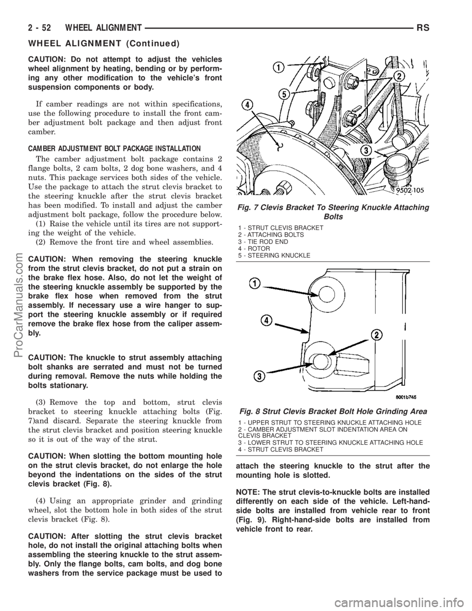
(3) Remove the top and bottom, strut clevis
bracket to steering knuckle attaching bolts (Fig.
7)and discard. Separate the steering knuckle from
the strut clevis bracket and position steering knuckle
so it is out of the way of the strut.
CAUTION: When slotting the bottom mounting hole
on the strut clevis bracket, do not enlarge the hole
beyond the indentations on the sides of the strut
clevis bracket (Fig. 8).
(4) Using an appropriate grinder and grinding
wheel, slot the bottom hole in both sides of the strut
clevis bracket (Fig. 8).
CAUTION: After slotting the strut clevis bracket
hole, do not install the original attaching bolts when
assembling the steering knuckle to the strut assem-
bly. Only the flange bolts, cam bolts, and dog bone
washers from the service package must be used toattach the steering knuckle to the strut after the
mounting hole is slotted.
NOTE: The strut clevis-to-knuckle bolts are installed
differently on each side of the vehicle. Left-hand-
side bolts are installed from vehicle rear to front
(Fig. 9). Right-hand-side bolts are installed from
vehicle front to rear.
Fig. 7 Clevis Bracket To Steering Knuckle Attaching
Bolts
1 - STRUT CLEVIS BRACKET
2 - ATTACHING BOLTS
3 - TIE ROD END
4 - ROTOR
5 - STEERING KNUCKLE
Fig. 8 Strut Clevis Bracket Bolt Hole Grinding Area
1 - UPPER STRUT TO STEERING KNUCKLE ATTACHING HOLE
2 - CAMBER ADJUSTMENT SLOT INDENTATION AREA ON
CLEVIS BRACKET
3 - LOWER STRUT TO STEERING KNUCKLE ATTACHING HOLE
4 - STRUT CLEVIS BRACKET
2 - 52 WHEEL ALIGNMENTRS
WHEEL ALIGNMENT (Continued)
ProCarManuals.com
Page 100 of 2177

DIFFERENTIAL & DRIVELINE
TABLE OF CONTENTS
page page
HALF SHAFT - FRONT.....................1
HALF SHAFT - REAR.....................13PROPELLER SHAFT.....................21
REAR DRIVELINE MODULE................23
HALF SHAFT - FRONT
TABLE OF CONTENTS
page page
HALF SHAFT - FRONT
DESCRIPTION..........................1
DIAGNOSIS AND TESTING - HALF SHAFT.....1
REMOVAL.............................2
INSTALLATION..........................4
SPECIFICATIONS - HALF SHAFT - FRONT....6CV BOOT - INNER
REMOVAL.............................6
INSTALLATION..........................6
CV BOOT - OUTER
REMOVAL.............................10
INSTALLATION.........................10
HALF SHAFT - FRONT
DESCRIPTION
All vehicles use an unequal length half shaft sys-
tem (Fig. 1).
The left half shaft uses a tuned rubber damper
weight. When replacing the left half shaft, be sure
the replacement half shaft has the same damper
weight as the original.
All half shaft assemblies use the same type of
inner and outer joints. The inner joint of both half
shaft assemblies is a tripod joint, and the outer joint
of both half shaft assemblies is a Rzeppa joint. Both
tripod joints and Rzeppa joints are true constant
velocity (CV) joint assemblies. The inner tripod joint
allows for the changes in half shaft length through
the jounce and rebound travel of the front suspen-
sion.
On vehicles equipped with ABS brakes, the outer
CV joint is equipped with a tone wheel used to deter-
mine vehicle speed for ABS brake operation.
The inner tripod joint of both half shafts is splined
into the transaxle side gears. The inner tripod joints
are retained in the side gears of the transaxle using
a snap ring located in the stub shaft of the tripod
joint. The outer CV joint has a stub shaft that is
splined into the wheel hub and retained by a steel
hub nut.
DIAGNOSIS AND TESTING - HALF SHAFT
VEHICLE INSPECTION
(1) Check for grease in the vicinity of the inboard
tripod joint and outboard CV joint; this is a sign of
inner or outer joint seal boot or seal boot clamp dam-
age.
NOISE AND/OR VIBRATION IN TURNS
A clicking noise and/or a vibration in turns could
be caused by one of the following conditions:
²Damaged outer CV or inner tripod joint seal
boot or seal boot clamps. This will result in the loss
and/or contamination of the joint grease, resulting in
inadequate lubrication of the joint.
²Noise may also be caused by another component
of the vehicle coming in contact with the half shafts.
CLUNKING NOISE DURING ACCELERATION
This noise may be a result of one of the following
conditions:
²A torn seal boot on the inner or outer joint of the
half shaft assembly.
²A loose or missing clamp on the inner or outer
joint of the half shaft assembly.
²A damaged or worn half shaft CV joint.
RSDIFFERENTIAL & DRIVELINE3-1
ProCarManuals.com
Page 101 of 2177

SHUDDER OR VIBRATION DURING ACCELERATION
This problem could be a result of:
²A worn or damaged half shaft inner tripod joint.
²A sticking tripod joint spider assembly (inner tri-
pod joint only).
²Improper wheel alignment. (Refer to 2 - SUS-
PENSION/WHEEL ALIGNMENT - STANDARD
PROCEDURE)
VIBRATION AT HIGHWAY SPEEDS
This problem could be a result of:
²Foreign material (mud, etc.) packed on the back-
side of the wheel(s).
²Out of balance tires or wheels. (Refer to 22 -
TIRES/WHEELS - STANDARD PROCEDURE)
²Improper tire and/or wheel runout. (Refer to 22 -
TIRES/WHEELS - DIAGNOSIS AND TESTING)
REMOVAL
(1) Raise vehicle.
(2) Remove the cotter pin and nut lock (Fig. 2)
from the end of the half shaft.
(3) Remove the wheel and tire assembly from the
vehicle. (Refer to 22 - TIRES/WHEELS - REMOVAL)
(4) Remove the wave washer (Fig. 3) from the end
of the half shaft.(5) With the vehicle's brakes applied to keep hub
from turning,loosen and removethe half shaft
nut.
(6) Remove the two front disc brake caliper
adapter to steering knuckle attaching bolts (Fig. 4).
Fig. 1 Unequal Length Half Shaft System
1 - STUB AXLE 8 - OUTER C/V JOINT
2 - OUTER C/V JOINT 9 - RIGHT HALFSHAFT
3 - OUTER C/V JOINT BOOT 10 - INNER TRIPOD JOINT BOOT
4 - TUNED RUBBER DAMPER WEIGHT 11 - INNER TRIPOD JOINT
5 - INTERCONNECTING SHAFT 12 - INNER TRIPOD JOINT
6 - OUTER C/V JOINT BOOT 13 - INNER TRIPOD JOINT BOOT
7 - STUB AXLE 14 - INTERCONNECTING SHAFT LEFT HALFSHAFT
Fig. 2 Half Shaft Retaining Nut
1 - HUB/BEARING
2 - NUT LOCK
3 - COTTER PIN
4 - STUB AXLE
3 - 2 HALF SHAFT - FRONTRS
HALF SHAFT - FRONT (Continued)
ProCarManuals.com
Page 161 of 2177
plug from the adjustment hole in each brake support
plate to provide visual access of the brake adjuster
star wheel.
To eliminate the condition where maximum adjust-
ment of the rear brake shoes does not allow the auto-
matic adjuster to operate when tested, back the star
wheel off approximately 30 notches. It will be neces-
sary to hold the adjuster lever away from the star
wheel to permit this adjustment.
Have the helper apply the brakes. Upon applica-
tion of the brake pedal, the adjuster lever should
move down, turning the adjuster star wheel. Thus, a
definite rotation of the adjuster star wheel can be
observed if the automatic adjuster is working prop-
erly. If one or more adjusters do not function prop-
erly, the respective drum must be removed for
adjuster servicing.
BRAKE LINES
DESCRIPTION - BRAKE TUBES AND HOSES
The brake tubes are steel with a corrosion-resis-
tant nylon coating applied to the external surfaces.
The flex hoses are made of reinforced rubber with fit-
tings at each end.
The primary and secondary brake tubes leading
from the master cylinder to the ABS ICU Hydraulic
Control Unit (HCU) or the non-ABS junction block
have a special flexible section. This flexible section is
required due to cradle movement while the vehicle is
in motion (The ICU and non-ABS junction block are
mounted to the cradle).If replacement of these
lines is necessary, only the original factory
brake line containing the flexible section must
be used.
OPERATION - BRAKE TUBES AND HOSES
The purpose of the chassis brake tubes and flex
hoses is to transfer the pressurized brake fluid devel-
oped by the master cylinder to the wheel brakes of
the vehicle. The flex hoses are made of rubber to
allow for the movement of the vehicle's suspension.
INSPECTION - BRAKE TUBES AND HOSES
Flexible rubber hose is used at both front brakes
and at the rear axle. Inspection of brake hoses
should be performed whenever the brake system is
serviced and every 7,500 miles or 12 months, which-
ever comes first (every engine oil change). Inspect
hydraulic brake hoses for surface cracking, scuffing,
or worn spots. If the fabric casing of the rubber hose
becomes exposed due to cracks or abrasions in the
rubber hose cover, the hose should be replaced imme-
diately. Eventual deterioration of the hose can take
place with possible burst failure. Faulty installation
can cause twisting, resulting in wheel, tire, or chassis
interference.
The brake tubing should be inspected periodically
for evidence of physical damage or contact with mov-
ing or hot components.
The flexible brake tube sections used on this vehi-
cle in the primary and secondary tubes from the
master cylinder to the ABS hydraulic control unit
connections must also be inspected. This flexible tub-
ing must be inspected for kinks, fraying and contact
with other components or with the body of the vehi-
cle.
BRAKE PADS/SHOES - FRONT
REMOVAL
REMOVAL - FRONT DISC BRAKE SHOES
(DISC/DISC BRAKES)
(1) Raise the vehicle. (Refer to LUBRICATION &
MAINTENANCE/HOISTING - STANDARD PROCE-
DURE).
(2) Remove both front wheel and tire assemblies.
(3) Begin on one side of the vehicle.
(4) Remove the anti-rattle clip from the outboard
side of the caliper and adapter.
(5) Remove the two caliper guide pin bolts.
(6) Remove caliper from caliper adapter and brake
rotor.
CAUTION: Supporting weight of caliper by the flex-
ible brake fluid hose can damage the hose.
(7) Using wire or cord, hang the caliper from the
front strut assembly (Fig. 12). Support the caliper
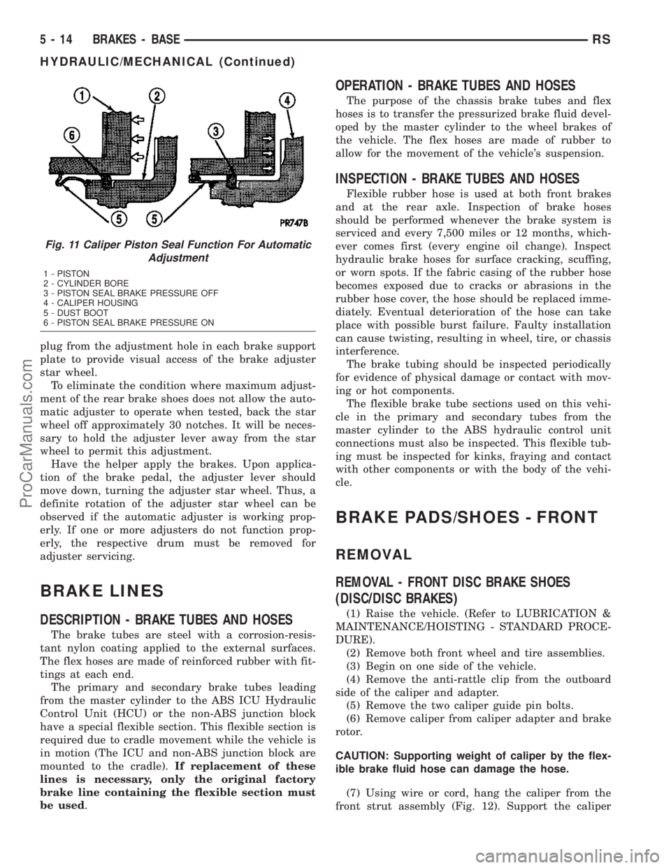
Fig. 11 Caliper Piston Seal Function For Automatic
Adjustment
1 - PISTON
2 - CYLINDER BORE
3 - PISTON SEAL BRAKE PRESSURE OFF
4 - CALIPER HOUSING
5 - DUST BOOT
6 - PISTON SEAL BRAKE PRESSURE ON
5 - 14 BRAKES - BASERS
HYDRAULIC/MECHANICAL (Continued)
ProCarManuals.com
Page 162 of 2177
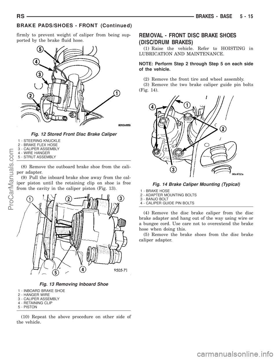
firmly to prevent weight of caliper from being sup-
ported by the brake fluid hose.
(8) Remove the outboard brake shoe from the cali-
per adapter.
(9) Pull the inboard brake shoe away from the cal-
iper piston until the retaining clip on shoe is free
from the cavity in the caliper piston (Fig. 13).
(10) Repeat the above procedure on other side of
the vehicle.REMOVAL - FRONT DISC BRAKE SHOES
(DISC/DRUM BRAKES)
(1) Raise the vehicle. Refer to HOISTING in
LUBRICATION AND MAINTENANCE.
NOTE: Perform Step 2 through Step 5 on each side
of the vehicle.
(2) Remove the front tire and wheel assembly.
(3) Remove the two brake caliper guide pin bolts
(Fig. 14).
(4) Remove the disc brake caliper from the disc
brake adapter and hang out of the way using wire or
a bungee cord. Use care not to overextend the brake
hose when doing this.
(5) Remove the brake shoes from the disc brake
caliper adapter.
Fig. 12 Stored Front Disc Brake Caliper
1 - STEERING KNUCKLE
2 - BRAKE FLEX HOSE
3 - CALIPER ASSEMBLY
4 - WIRE HANGER
5 - STRUT ASSEMBLY
Fig. 13 Removing Inboard Shoe
1 - INBOARD BRAKE SHOE
2 - HANGER WIRE
3 - CALIPER ASSEMBLY
4 - RETAINING CLIP
5 - PISTON
Fig. 14 Brake Caliper Mounting (Typical)
1 - BRAKE HOSE
2 - ADAPTER MOUNTING BOLTS
3 - BANJO BOLT
4 - CALIPER GUIDE PIN BOLTS
RSBRAKES - BASE5-15
BRAKE PADS/SHOES - FRONT (Continued)
ProCarManuals.com
Page 164 of 2177

tightening sequence to the full specified torque of 135
N´m (100 ft. lbs.).
(13) Lower vehicle.
(14) Pump the brake pedal several times. This will
set the shoes to the brake rotor.
(15) Check and adjust brake fluid level as neces-
sary.
(16) Road test the vehicle and make several stops
to wear off any foreign material on the brakes and to
seat the brake shoes.
INSTALLATION - FRONT DISC BRAKE SHOES
(DISC/DRUM BRAKES)
NOTE: Perform steps Step 1 through Step 5on each
side of the vehicle.
(1) Place the brake shoes in the adapter anti-rattle
clips.
(2) Completely retract the caliper piston back into
the bore of the caliper.
CAUTION: Use care when installing the caliper onto
the disc brake adapter to avoid damaging the boots
on the caliper guide pins.
(3) Install the disc brake caliper over the brake
shoes on the brake caliper adapter.
(4) Align the caliper guide pin bolt holes with the
guide pins. Install the caliper guide pin bolts and
tighten them to a torque of 35 N´m (26 ft. lbs.) (Fig.
14).
(5) Install the tire and wheel assembly. Tighten
the wheel mounting nuts to a torque of 135 N´m (100
ft. lbs.).
(6) Lower the vehicle.
(7) Pump the brake pedal several times. This will
set the shoes to the brake rotor.
(8) Check and adjust the brake fluid level as nec-
essary.
(9) Road test the vehicle and make several stops to
wear off any foreign material on the brakes and to
seat the brake shoes.
BRAKE PADS/SHOES - REAR
DISC
REMOVAL - REAR DISC BRAKE SHOES
(1) Raise vehicle. (Refer to LUBRICATION &
MAINTENANCE/HOISTING - STANDARD PROCE-
DURE).
(2) Remove rear wheel and tire assemblies from
vehicle.
(3) Remove the caliper to adapter guide pin bolts
(Fig. 15).(4) Remove rear caliper from adapter using the fol-
lowing procedure. First rotate front of caliper up
from the adapter. Then pull the rear of the caliper
and the outboard brake shoe anti-rattle clip out from
under the rear abutment on the adapter (Fig. 16).
(5) Support caliper to prevent the weight of the
caliper from damaging the flexible brake hose (Fig.
17).
(6) If the brake rotor needs to be removed it can be
removed by removing the retainer clips and then
pulling the rotor straight off the wheel mounting
studs.
Fig. 15 Caliper Guide Pin Bolts
1 - DISC BRAKE CALIPER
2 - ADAPTER
3 - AXLE
4 - GUIDE PIN BOLTS
5 - DRIVESHAFT (AWD MODELS ONLY)
Fig. 16 Removing/Installing Caliper
1 - LIFT THIS END OF CALIPER AWAY FROM ADAPTER FIRST
2 - DISC BRAKE CALIPER
3 - ADAPTER ABUTMENT
4 - OUTBOARD BRAKE SHOE HOLD DOWN CLIP
5 - OUTBOARD BRAKE SHOE
6 - ROTOR
7 - ADAPTER
RSBRAKES - BASE5-17
BRAKE PADS/SHOES - FRONT (Continued)
ProCarManuals.com
Page 215 of 2177
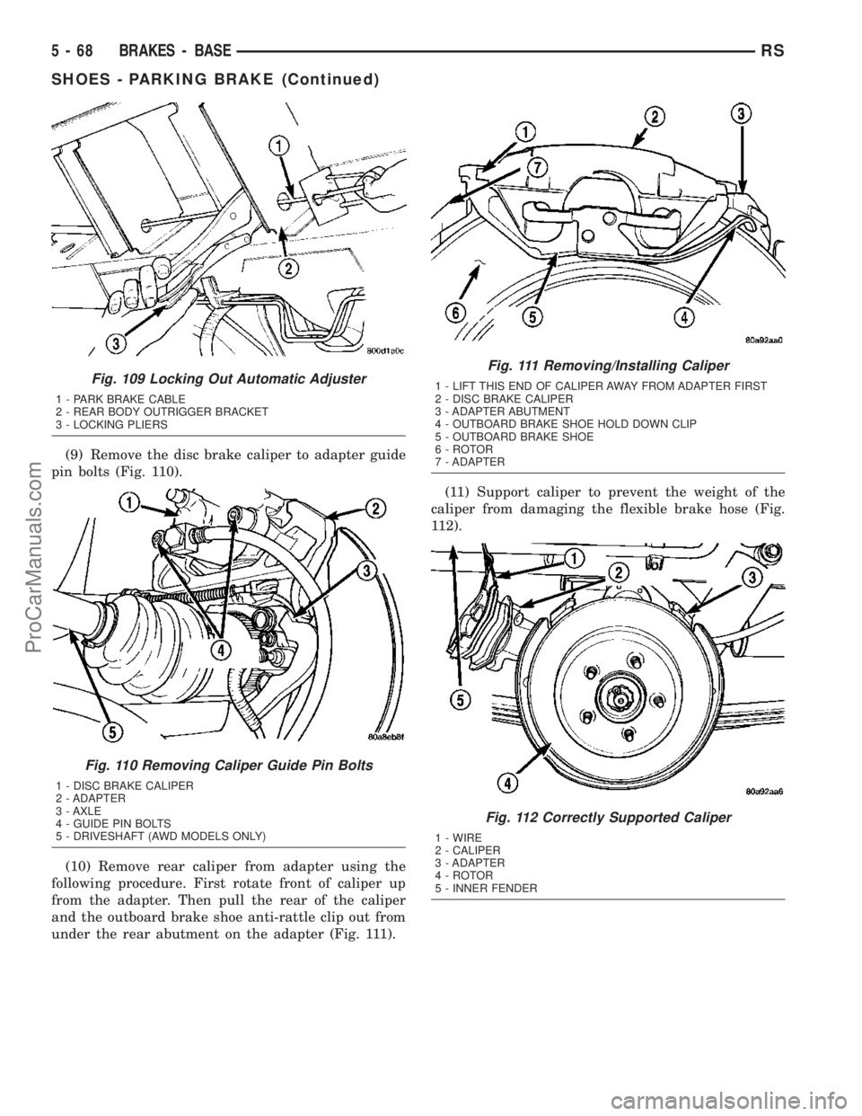
(9) Remove the disc brake caliper to adapter guide
pin bolts (Fig. 110).
(10) Remove rear caliper from adapter using the
following procedure. First rotate front of caliper up
from the adapter. Then pull the rear of the caliper
and the outboard brake shoe anti-rattle clip out from
under the rear abutment on the adapter (Fig. 111).(11) Support caliper to prevent the weight of the
caliper from damaging the flexible brake hose (Fig.
112).
Fig. 109 Locking Out Automatic Adjuster
1 - PARK BRAKE CABLE
2 - REAR BODY OUTRIGGER BRACKET
3 - LOCKING PLIERS
Fig. 110 Removing Caliper Guide Pin Bolts
1 - DISC BRAKE CALIPER
2 - ADAPTER
3 - AXLE
4 - GUIDE PIN BOLTS
5 - DRIVESHAFT (AWD MODELS ONLY)
Fig. 111 Removing/Installing Caliper
1 - LIFT THIS END OF CALIPER AWAY FROM ADAPTER FIRST
2 - DISC BRAKE CALIPER
3 - ADAPTER ABUTMENT
4 - OUTBOARD BRAKE SHOE HOLD DOWN CLIP
5 - OUTBOARD BRAKE SHOE
6 - ROTOR
7 - ADAPTER
Fig. 112 Correctly Supported Caliper
1 - WIRE
2 - CALIPER
3 - ADAPTER
4 - ROTOR
5 - INNER FENDER
5 - 68 BRAKES - BASERS
SHOES - PARKING BRAKE (Continued)
ProCarManuals.com
Page 432 of 2177
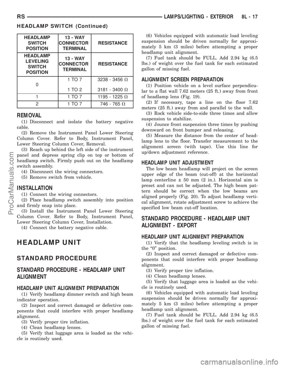
HEADLAMP
SWITCH
POSITION13-WAY
CONNECTOR
TERMINALRESISTANCE
HEADLAMP
LEVELING
SWITCH
POSITION13-WAY
CONNECTOR
TERMINALRESISTANCE
01 TO 7 3238 - 3456V
1 TO 2 3181 - 3400V
1 1 TO 7 1195 - 1225V
2 1 TO 7 746 - 765V
REMOVAL
(1) Disconnect and isolate the battery negative
cable.
(2) Remove the Instrument Panel Lower Steering
Column Cover. Refer to Body, Instrument Panel,
Lower Steering Column Cover, Removal.
(3) Reach up behind the left side of the instrument
panel and depress spring clip on top or bottom of
headlamp switch. Firmly push out on the headlamp
switch assembly.
(4) Disconnect the wiring connectors.
(5) Remove switch from vehicle.
INSTALLATION
(1) Connect the wiring connectors.
(2) Place headlamp switch assembly into position
and firmly snap into place.
(3) Install the Instrument Panel Lower Steering
Column Cover. Refer to Body, Instrument Panel,
Lower Steering Column Cover, Installation.
(4) Connect the battery negative cable.
HEADLAMP UNIT
STANDARD PROCEDURE
STANDARD PROCEDURE - HEADLAMP UNIT
ALIGNMENT
HEADLAMP UNIT ALIGNMENT PREPARATION
(1) Verify headlamp dimmer switch and high beam
indicator operation.
(2) Inspect and correct damaged or defective com-
ponents that could interfere with proper headlamp
alignment.
(3) Verify proper tire inflation.
(4) Clean headlamp lenses.
(5) Verify that luggage area is loaded as the vehi-
cle is routinely used.(6) Vehicles equipped with automatic load leveling
suspension should be driven normally for approxi-
mately 5 km (3 miles) before attempting a proper
headlamp unit alignment.
(7) Fuel tank should be FULL. Add 2.94 kg (6.5
lbs.) of weight over the fuel tank for each estimated
gallon of missing fuel.
ALIGNMENT SCREEN PREPARATION
(1) Position vehicle on a level surface perpendicu-
lar to a flat wall 7.62 meters (25 ft.) away from front
of headlamp lens (Fig. 19).
(2) If necessary, tape a line on the floor 7.62
meters (25 ft.) away from and parallel to the wall.
(3) Rock vehicle side-to-side three times and allow
suspension to stabilize.
(4) Jounce front suspension three times by pushing
downward on front bumper and releasing.
(5) Measure the distance from the center of head-
lamp lens to the floor. Transfer measurement to the
alignment screen (with tape). Use this line for
up/down adjustment reference.
HEADLAMP UNIT ADJUSTMENT
The low beam headlamp will project on the screen
upper edge of the beam (cut-off) at the horizontal
lamp centerline 50 mm (2 in.). Horizontal aim is
preset and can not be adjusted. The high beam pat-
tern should be correct when the low beams are
aligned properly (Fig. 20). To adjust headlamp verti-
cal alignment, rotate adjustment screw to achieve the
specified low beam cut-off location.
STANDARD PROCEDURE - HEADLAMP UNIT
ALIGNMENT - EXPORT
HEADLAMP UNIT ALIGNMENT PREPARATION
(1) Verify that the headlamp leveling switch is in
the ª0º position.
(2) Inspect and correct damaged or defective com-
ponents that could interfere with proper headlamp
alignment.
(3) Verify proper tire inflation.
(4) Clean headlamp lenses.
(5) Verify that luggage area is loaded as the vehi-
cle is routinely used.
(6) Vehicles equipped with automatic load leveling
suspension should be driven normally for approxi-
mately 5 km (3 miles) before attempting a proper
headlamp unit alignment.
(7) Fuel tank should be FULL. Add 2.94 kg (6.5
lbs.) of weight over the fuel tank for each estimated
gallon of missing fuel.
RSLAMPS/LIGHTING - EXTERIOR8L-17
HEADLAMP SWITCH (Continued)
ProCarManuals.com