towing CHRYSLER CARAVAN 2003 Service Manual
[x] Cancel search | Manufacturer: CHRYSLER, Model Year: 2003, Model line: CARAVAN, Model: CHRYSLER CARAVAN 2003Pages: 2177, PDF Size: 59.81 MB
Page 14 of 2177
LUBRICATION & MAINTENANCE
TABLE OF CONTENTS
page page
INTERNATIONAL SYMBOLS
DESCRIPTION..........................1
FLUID TYPES
DESCRIPTION
DESCRIPTION - ENGINE OIL AND
LUBRICANTS.........................1
DESCRIPTION - ENGINE COOLANT........3
DESCRIPTION - FLEXIBLE FUEL ENGINE
OIL .................................3
DESCRIPTION - TRANSMISSION FLUID.....4
DESCRIPTION - FUEL REQUIREMENTS.....4
DESCRIPTION - FUEL REQUIREMENTS -
DIESEL ENGINE.......................6
DESCRIPTION - ENGINE OIL - DIESEL
ENGINES............................6FLUID CAPACITIES
SPECIFICATIONS - FLUID CAPACITIES.......6
FLUID FILL/CHECK LOCATIONS
DESCRIPTION..........................7
LUBRICATION POINTS
DESCRIPTION..........................7
MAINTENANCE SCHEDULES
DESCRIPTION..........................7
HOISTING
STANDARD PROCEDURE - HOISTING.......15
JUMP STARTING
STANDARD PROCEDURE - JUMP STARTING...15
TOWING
STANDARD PROCEDURE - TOWING........17
INTERNATIONAL SYMBOLS
DESCRIPTION
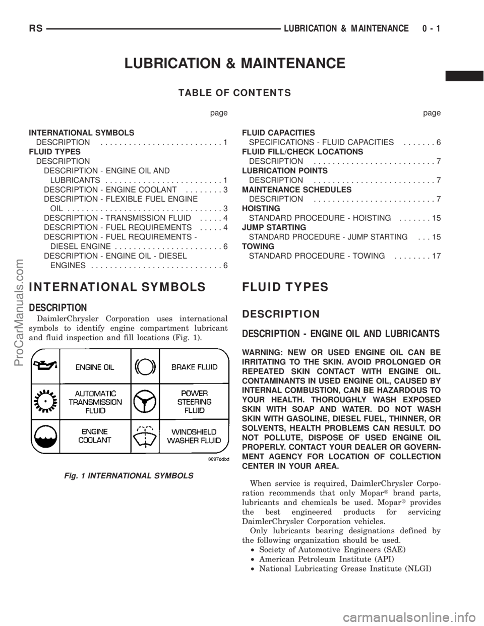
DaimlerChrysler Corporation uses international
symbols to identify engine compartment lubricant
and fluid inspection and fill locations (Fig. 1).
FLUID TYPES
DESCRIPTION
DESCRIPTION - ENGINE OIL AND LUBRICANTS
WARNING: NEW OR USED ENGINE OIL CAN BE
IRRITATING TO THE SKIN. AVOID PROLONGED OR
REPEATED SKIN CONTACT WITH ENGINE OIL.
CONTAMINANTS IN USED ENGINE OIL, CAUSED BY
INTERNAL COMBUSTION, CAN BE HAZARDOUS TO
YOUR HEALTH. THOROUGHLY WASH EXPOSED
SKIN WITH SOAP AND WATER. DO NOT WASH
SKIN WITH GASOLINE, DIESEL FUEL, THINNER, OR
SOLVENTS, HEALTH PROBLEMS CAN RESULT. DO
NOT POLLUTE, DISPOSE OF USED ENGINE OIL
PROPERLY. CONTACT YOUR DEALER OR GOVERN-
MENT AGENCY FOR LOCATION OF COLLECTION
CENTER IN YOUR AREA.
When service is required, DaimlerChrysler Corpo-
ration recommends that only Mopartbrand parts,
lubricants and chemicals be used. Mopartprovides
the best engineered products for servicing
DaimlerChrysler Corporation vehicles.
Only lubricants bearing designations defined by
the following organization should be used.
²Society of Automotive Engineers (SAE)
²American Petroleum Institute (API)
²National Lubricating Grease Institute (NLGI)
Fig. 1 INTERNATIONAL SYMBOLS
RSLUBRICATION & MAINTENANCE0-1
ProCarManuals.com
Page 20 of 2177
FLUID FILL/CHECK
LOCATIONS
DESCRIPTION
The fluid check/fill point locations are located in
each applicable service manual section.
LUBRICATION POINTS
DESCRIPTION
Lubrication point locations are located in each
applicable Sections.
MAINTENANCE SCHEDULES
DESCRIPTION
Maintenance Schedule Information not included in
this section, is located in the appropriate Owner's
Manual.
First is ScheduleªBº. It is for vehicles that are
operated under the conditions that are listed below
and at the beginning of the schedule.
²Day or night temperatures are below 0É C (32É
F).
²Stop and go driving.
²Extensive engine idling.
²Driving in dusty conditions.
²Short trips of less than 16 km (10 miles).
²More than 50% of your driving is at sustained
high speeds during hot weather, above 32É C (90É
F).L
²Trailer towing.L
²Taxi, police, or delivery service (commercial ser-
vice).L
²Off-road or desert operation.
²If equipped for and operating with E-85
(ethanol) fuel.
NOTE: Most vehicles are operated under the condi-
tions listed for Schedule(B(.
Second is ScheduleªAº. It is for vehicles that are
not operated under any of the conditions listed under
Schedule9B9.
Use the schedule that best describes your driving
conditions. Where time and mileage are listed, follow
the interval that occurs first.
CAUTION: Failure to perform the required mainte-
nance items may result in damage to the vehicle.
At Each Stop for Fuel
²Check the engine oil level about 5 minutes after a
fully warmed engine is shut off. Checking the oil level
while the vehicle is on level ground will improve the
accuracy of the oil level reading. Add oil only when the
level is at or below the ADD or MIN mark.
²Check the windshield washer solvent and add if
required.
Once a Month
²Check tire pressure and look for unusual wear
or damage.
²Inspect the battery and clean and tighten the
terminals as required.
²Check the fluid levels of coolant reservoir, brake
master cylinder, power steering and transmission
and add as needed.
²Check all lights and all other electrical items for
correct operation.
At Each Oil Change
²Change the engine oil filter.
²Inspect the exhaust system.
²Inspect the brake hoses.
²Inspect the CV joints and front suspension com-
ponents.
²Check the automatic transmission fluid level.
²Check the coolant level, hoses, and clamps.
²Rotate the tires at each oil change interval
shown on Schedule ªAº 10 000 km (6,000 miles) or
every other interval shown on Schedule ªBº 10 000
km (6,000 miles).
SCHEDULE ªBº
Follow schedule ªBº if you usually operate your
vehicle under one or more of the following conditions.
Change the automatic transmission fluid and filter
every 77 000 km (48,000 miles) if the vehicle is usu-
ally operated under one or more of the conditions
marked with anL.
²
Day or night temperatures are below 0É C (32É F).
²Stop and go driving.
²Extensive engine idling.
²Driving in dusty conditions.
²Short trips of less than 16 km (10 miles).
²More than 50% of your driving is at sustained
high speeds during hot weather, above 32É C
(90É F).L
²Trailer towing.L
²Taxi, police, or delivery service (commercial ser-
vice).L
²Off-road or desert operation.
²If equipped for and operating with E-85
(ethanol) fuel.
RSLUBRICATION & MAINTENANCE0-7
ProCarManuals.com
Page 30 of 2177
TOWING
STANDARD PROCEDURE - TOWING
WARNINGS AND CAUTIONS
WARNING: DO NOT ALLOW TOWING ATTACHMENT
DEVICES TO CONTACT THE FUEL TANK OR LINES,
FUEL LEAK CAN RESULT.
DO NOT LIFT OR TOW VEHICLE BY FRONT OR
REAR BUMPER.
DO NOT GO UNDER A LIFTED VEHICLE IF NOT
SUPPORTED PROPERLY ON SAFETY STANDS.
DO NOT ALLOW PASSENGERS TO RIDE IN A
TOWED VEHICLE.
USE A SAFETY CHAIN THAT IS INDEPENDENT
FROM THE TOWING ATTACHMENT DEVICE.
CAUTION: Do not damage brake lines, exhaust sys-
tem, shock absorbers, sway bars, or any other
under vehicle components when attaching towing
device to vehicle.
Do not secure vehicle to towing device by the use
of front or rear suspension or steering components.
Remove or secure loose or protruding objects from
a damaged vehicle before towing.
Refer to state and local rules and regulations before
towing a vehicle.
Do not allow weight of towed vehicle to bear on
lower fascia, air dams, or spoilers.
RECOMMENDED TOWING EQUIPMENT
To avoid damage to bumper fascia and air dams
use:
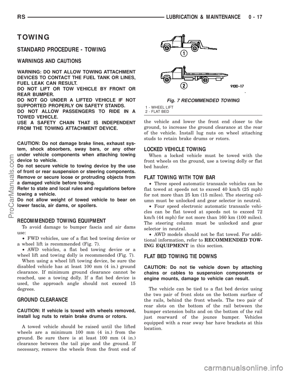
²FWD vehicles, use of a flat bed towing device or
a wheel lift is recommended (Fig. 7).
²AWD vehicles, a flat bed towing device or a
wheel lift and towing dolly is recommended (Fig. 7).
When using a wheel lift towing device, be sure the
disabled vehicle has at least 100 mm (4 in.) ground
clearance. If minimum ground clearance cannot be
reached, use a towing dolly. If a flat bed device is
used, the approach angle should not exceed 15
degrees.
GROUND CLEARANCE
CAUTION: If vehicle is towed with wheels removed,
install lug nuts to retain brake drums or rotors.
A towed vehicle should be raised until the lifted
wheels are a minimum 100 mm (4 in.) from the
ground. Be sure there is at least 100 mm (4 in.)
clearance between the tail pipe and the ground. If
necessary, remove the wheels from the front end ofthe vehicle and lower the front end closer to the
ground, to increase the ground clearance at the rear
of the vehicle. Install lug nuts on wheel attaching
studs to retain brake drums or rotors.
LOCKED VEHICLE TOWING
When a locked vehicle must be towed with the
front wheels on the ground, use a towing dolly or flat
bed hauler.
FLAT TOWING WITH TOW BAR
²Three speed automatic transaxle vehicles can be
flat towed at speeds not to exceed 40 km/h (25 mph)
for not more than 25 km (15 miles). The steering col-
umn must be unlocked and gear selector in neutral.
²Four speed electronic automatic transaxle vehi-
cles can be flat towed at speeds not to exceed 72
km/h (44 mph) for not more than 160 km (100 miles).
The steering column must be unlocked and gear
selector in neutral.
²AWD models should not be flat towed. For addi-
tional information, refer toRECOMMENDED TOW-
ING EQUIPMENTin this section.
FLAT BED TOWING TIE DOWNS
CAUTION: Do not tie vehicle down by attaching
chains or cables to suspension components or
engine mounts, damage to vehicle can result.
The vehicle can be tied to a flat bed device using
the two pair of front slots on the bottom surface of
the rails, behind the front wheels. The two pair of
rear slots on the bottom of the rail between the
bumper extension bolts and on the bottom of the rail
just rearward of the jounce bumper. Vehicles
equipped with a rear sway bar have brackets at this
location.
Fig. 7 RECOMMENDED TOWING
1 - WHEEL LIFT
2 - FLAT BED
RSLUBRICATION & MAINTENANCE0-17
ProCarManuals.com
Page 31 of 2177
TOWING ± FRONT WHEEL LIFT
If the vehicle is being towed from the front, when-
ever possible ensure at least 10 inches road clearance
to the tires.
TOWING ± REAR WHEEL LIFT
If a vehicle cannot be towed with the front wheels
lifted, the rear wheels can be lifted provided the fol-
lowing guide lines are observed.
CAUTION: Do not use steering column lock to
secure steering wheel during towing operation.
²On AWD vehicles, all four wheels must be free to
rotate. Use towing dollies at unlifted end of vehicle.²Unlock steering column and secure steering
wheel in straight ahead position with a clamp device
designed for towing.
²Three speed automatic transaxle vehicles can be
flat towed at speeds not to exceed 40 km/h (25 mph)
for not more than 25 km (15 miles). The steering col-
umn must be unlocked and gear selector in neutral.
²Four speed electronic automatic transaxle vehi-
cles can be flat towed at speeds not to exceed 72
km/h (44 mph) for not more than 160 km (100 miles).
The steering column must be unlocked and gear
selector in neutral.
0 - 18 LUBRICATION & MAINTENANCERS
TOWING (Continued)
ProCarManuals.com
Page 32 of 2177
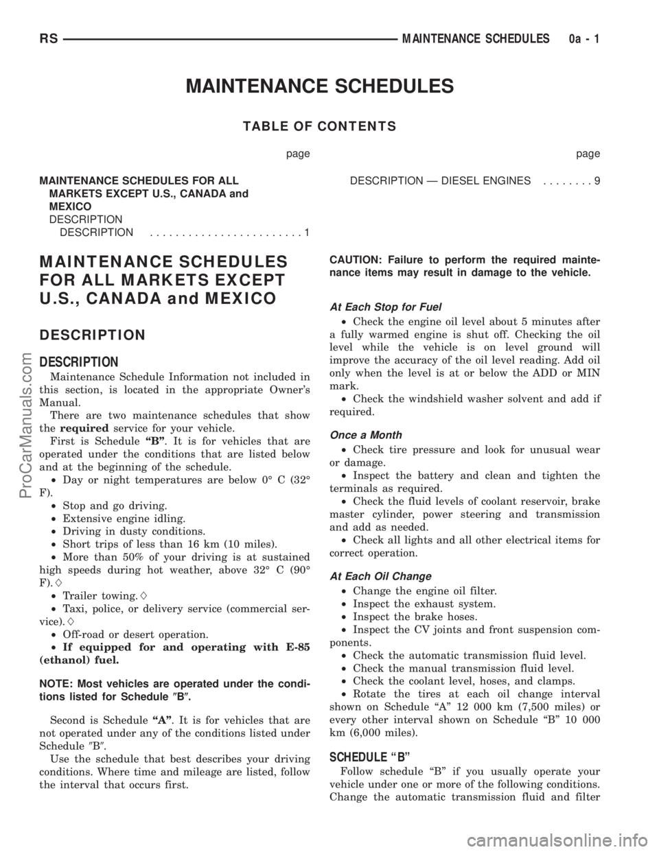
MAINTENANCE SCHEDULES
TABLE OF CONTENTS
page page
MAINTENANCE SCHEDULES FOR ALL
MARKETS EXCEPT U.S., CANADA and
MEXICO
DESCRIPTION
DESCRIPTION........................1DESCRIPTION Ð DIESEL ENGINES........9
MAINTENANCE SCHEDULES
FOR ALL MARKETS EXCEPT
U.S., CANADA and MEXICO
DESCRIPTION
DESCRIPTION
Maintenance Schedule Information not included in
this section, is located in the appropriate Owner's
Manual.
There are two maintenance schedules that show
therequiredservice for your vehicle.
First is ScheduleªBº. It is for vehicles that are
operated under the conditions that are listed below
and at the beginning of the schedule.
²Day or night temperatures are below 0É C (32É
F).
²Stop and go driving.
²Extensive engine idling.
²Driving in dusty conditions.
²Short trips of less than 16 km (10 miles).
²More than 50% of your driving is at sustained
high speeds during hot weather, above 32É C (90É
F).L
²Trailer towing.L
²Taxi, police, or delivery service (commercial ser-
vice).L
²Off-road or desert operation.
²If equipped for and operating with E-85
(ethanol) fuel.
NOTE: Most vehicles are operated under the condi-
tions listed for Schedule(B(.
Second is ScheduleªAº. It is for vehicles that are
not operated under any of the conditions listed under
Schedule9B9.
Use the schedule that best describes your driving
conditions. Where time and mileage are listed, follow
the interval that occurs first.CAUTION: Failure to perform the required mainte-
nance items may result in damage to the vehicle.
At Each Stop for Fuel
²Check the engine oil level about 5 minutes after
a fully warmed engine is shut off. Checking the oil
level while the vehicle is on level ground will
improve the accuracy of the oil level reading. Add oil
only when the level is at or below the ADD or MIN
mark.
²Check the windshield washer solvent and add if
required.
Once a Month
²Check tire pressure and look for unusual wear
or damage.
²Inspect the battery and clean and tighten the
terminals as required.
²Check the fluid levels of coolant reservoir, brake
master cylinder, power steering and transmission
and add as needed.
²Check all lights and all other electrical items for
correct operation.
At Each Oil Change
²Change the engine oil filter.
²Inspect the exhaust system.
²Inspect the brake hoses.
²Inspect the CV joints and front suspension com-
ponents.
²Check the automatic transmission fluid level.
²Check the manual transmission fluid level.
²Check the coolant level, hoses, and clamps.
²Rotate the tires at each oil change interval
shown on Schedule ªAº 12 000 km (7,500 miles) or
every other interval shown on Schedule ªBº 10 000
km (6,000 miles).
SCHEDULE ªBº
Follow schedule ªBº if you usually operate your
vehicle under one or more of the following conditions.
Change the automatic transmission fluid and filter
RSMAINTENANCE SCHEDULES0a-1
ProCarManuals.com
Page 33 of 2177
every 77 000 km (48,000 miles) if the vehicle is usu-
ally operated under one or more of the conditions
marked with anL.
²
Day or night temperatures are below 0É C (32É F).
²Stop and go driving.
²Extensive engine idling.
²Driving in dusty conditions.
²Short trips of less than 16 km (10 miles).²
More than 50% of your driving is at sustained high
speeds during hot weather, above 32É C (90É F).L
²Trailer towing.L
²Taxi, police, or delivery service (commercial ser-
vice).L
²Off-road or desert operation.
²If equipped for and operating with E-85
(ethanol) fuel.
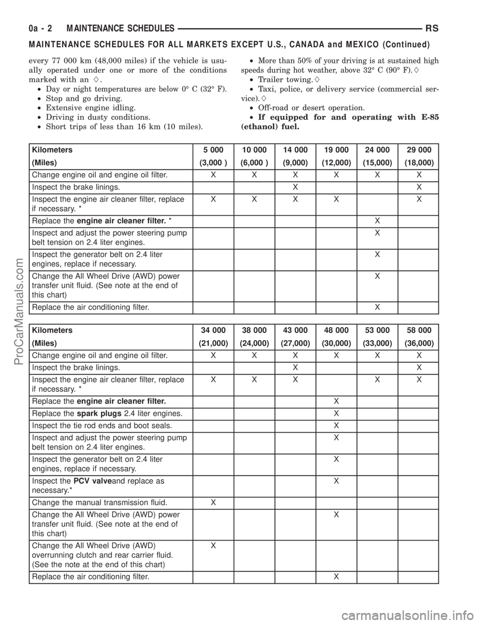
Kilometers 5 000 10 000 14 000 19 000 24 000 29 000
(Miles) (3,000 ) (6,000 ) (9,000) (12,000) (15,000) (18,000)
Change engine oil and engine oil filter.XXXXX X
Inspect the brake linings. X X
Inspect the engine air cleaner filter, replace
if necessary. *XXXX X
Replace theengine air cleaner filter.*X
Inspect and adjust the power steering pump
belt tension on 2.4 liter engines.X
Inspect the generator belt on 2.4 liter
engines, replace if necessary.X
Change the All Wheel Drive (AWD) power
transfer unit fluid. (See note at the end of
this chart)X
Replace the air conditioning filter. X
Kilometers 34 000 38 000 43 000 48 000 53 000 58 000
(Miles) (21,000) (24,000) (27,000) (30,000) (33,000) (36,000)
Change engine oil and engine oil filter.XXXXX X
Inspect the brake linings. X X
Inspect the engine air cleaner filter, replace
if necessary. *XXX X X
Replace theengine air cleaner filter.X
Replace thespark plugs2.4 liter engines. X
Inspect the tie rod ends and boot seals. X
Inspect and adjust the power steering pump
belt tension on 2.4 liter engines.X
Inspect the generator belt on 2.4 liter
engines, replace if necessary.X
Inspect thePCV valveand replace as
necessary.*X
Change the manual transmission fluid. X
Change the All Wheel Drive (AWD) power
transfer unit fluid. (See note at the end of
this chart)X
Change the All Wheel Drive (AWD)
overrunning clutch and rear carrier fluid.
(See the note at the end of this chart)X
Replace the air conditioning filter. X
0a - 2 MAINTENANCE SCHEDULESRS
MAINTENANCE SCHEDULES FOR ALL MARKETS EXCEPT U.S., CANADA and MEXICO (Continued)
ProCarManuals.com
Page 40 of 2177
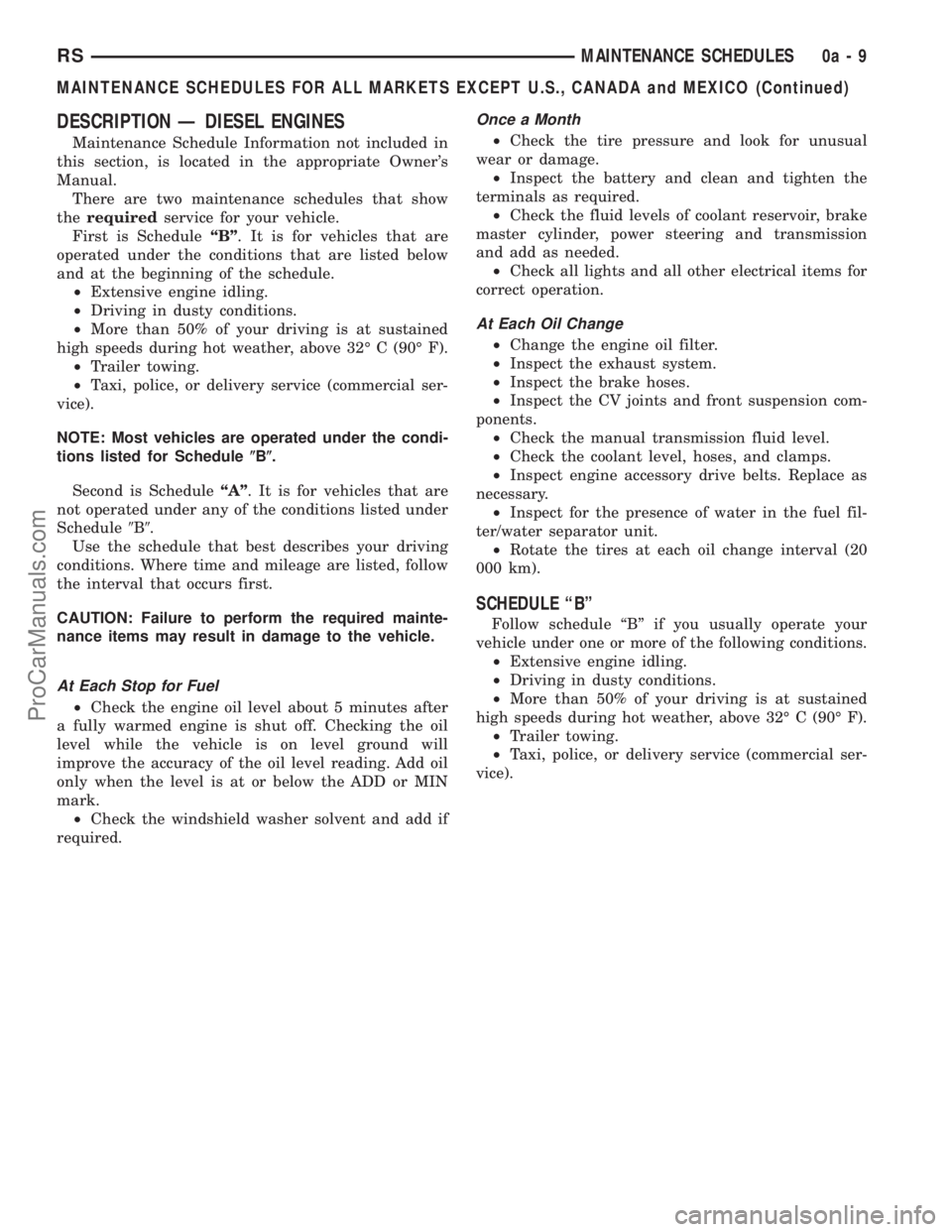
DESCRIPTION Ð DIESEL ENGINES
Maintenance Schedule Information not included in
this section, is located in the appropriate Owner's
Manual.
There are two maintenance schedules that show
therequiredservice for your vehicle.
First is ScheduleªBº. It is for vehicles that are
operated under the conditions that are listed below
and at the beginning of the schedule.
²Extensive engine idling.
²Driving in dusty conditions.
²More than 50% of your driving is at sustained
high speeds during hot weather, above 32É C (90É F).
²Trailer towing.
²Taxi, police, or delivery service (commercial ser-
vice).
NOTE: Most vehicles are operated under the condi-
tions listed for Schedule(B(.
Second is ScheduleªAº. It is for vehicles that are
not operated under any of the conditions listed under
Schedule9B9.
Use the schedule that best describes your driving
conditions. Where time and mileage are listed, follow
the interval that occurs first.
CAUTION: Failure to perform the required mainte-
nance items may result in damage to the vehicle.
At Each Stop for Fuel
²Check the engine oil level about 5 minutes after
a fully warmed engine is shut off. Checking the oil
level while the vehicle is on level ground will
improve the accuracy of the oil level reading. Add oil
only when the level is at or below the ADD or MIN
mark.
²Check the windshield washer solvent and add if
required.
Once a Month
²Check the tire pressure and look for unusual
wear or damage.
²Inspect the battery and clean and tighten the
terminals as required.
²Check the fluid levels of coolant reservoir, brake
master cylinder, power steering and transmission
and add as needed.
²Check all lights and all other electrical items for
correct operation.
At Each Oil Change
²Change the engine oil filter.
²Inspect the exhaust system.
²Inspect the brake hoses.
²Inspect the CV joints and front suspension com-
ponents.
²Check the manual transmission fluid level.
²Check the coolant level, hoses, and clamps.
²Inspect engine accessory drive belts. Replace as
necessary.
²Inspect for the presence of water in the fuel fil-
ter/water separator unit.
²Rotate the tires at each oil change interval (20
000 km).
SCHEDULE ªBº
Follow schedule ªBº if you usually operate your
vehicle under one or more of the following conditions.
²Extensive engine idling.
²Driving in dusty conditions.
²More than 50% of your driving is at sustained
high speeds during hot weather, above 32É C (90É F).
²Trailer towing.
²Taxi, police, or delivery service (commercial ser-
vice).
RSMAINTENANCE SCHEDULES0a-9
MAINTENANCE SCHEDULES FOR ALL MARKETS EXCEPT U.S., CANADA and MEXICO (Continued)
ProCarManuals.com
Page 273 of 2177
ENGINE
DIAGNOSIS AND TESTING - ENGINE COOLING
SYSTEM
Establish what driving condition caused the cooling
system complaint. The problem may be caused by an
abnormal load on the system such as the following:
prolonged idle, very high ambient temperature, slight
tail wind at idle, slow traffic speed, traffic jam, high
speed, steep grade.
DRIVING TECHNIQUES
To avoid overheating the cooling system:
(1) Idle with A/C off when temperature gauge is at
end of normal range.
(2) Do not increase engine speed for more air flow
and coolant flow because the electric motor fan sys-
tems are not responsive to engine RPM. The added
cooling from higher coolant flow rate is more than
offset by increased heat rejection (engine heat added
to coolant).
TRAILER TOWING
Consult the owner's manual under Trailer Towing
and do not exceed specified limits.
VISUAL INSPECTION
If the cooling system problem is not caused by a
driving condition, perform a visual inspection to
determine if there was a recent service or accident
repair, including the following:
²Loose/damaged water pump drive belt
²Incorrect cooling system refilling (trapped air or
low level)
²Brakes possibly dragging
²Damaged hoses
²Loose/damaged hose clamps
²Damaged/incorrect engine thermostat
²Damaged cooling fan motor, fan blade and fan
shroud
²Damaged head gasket
²Damaged water pump
²Damaged radiator
²Damaged coolant recovery system
²Damaged heater core
²Open/shorted electrical circuits
If the visual inspection reveals none of the above
as cause for a cooling system complaint, refer to the
following diagnostic charts.
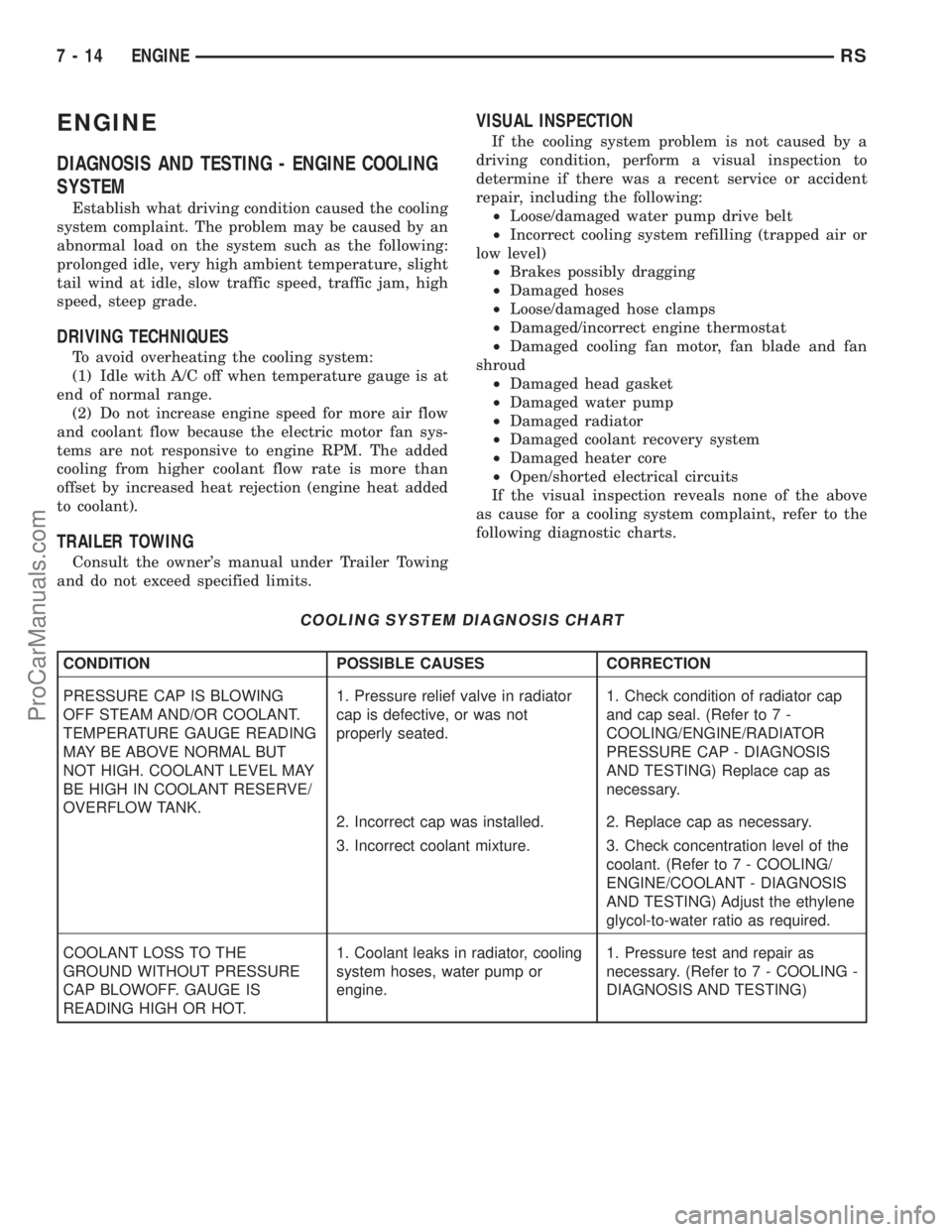
COOLING SYSTEM DIAGNOSIS CHART
CONDITION POSSIBLE CAUSES CORRECTION
PRESSURE CAP IS BLOWING
OFF STEAM AND/OR COOLANT.
TEMPERATURE GAUGE READING
MAY BE ABOVE NORMAL BUT
NOT HIGH. COOLANT LEVEL MAY
BE HIGH IN COOLANT RESERVE/
OVERFLOW TANK.1. Pressure relief valve in radiator
cap is defective, or was not
properly seated.1. Check condition of radiator cap
and cap seal. (Refer to 7 -
COOLING/ENGINE/RADIATOR
PRESSURE CAP - DIAGNOSIS
AND TESTING) Replace cap as
necessary.
2. Incorrect cap was installed. 2. Replace cap as necessary.
3. Incorrect coolant mixture. 3. Check concentration level of the
coolant. (Refer to 7 - COOLING/
ENGINE/COOLANT - DIAGNOSIS
AND TESTING) Adjust the ethylene
glycol-to-water ratio as required.
COOLANT LOSS TO THE
GROUND WITHOUT PRESSURE
CAP BLOWOFF. GAUGE IS
READING HIGH OR HOT.1. Coolant leaks in radiator, cooling
system hoses, water pump or
engine.1. Pressure test and repair as
necessary. (Refer to 7 - COOLING -
DIAGNOSIS AND TESTING)
7 - 14 ENGINERS
ProCarManuals.com
Page 1403 of 2177
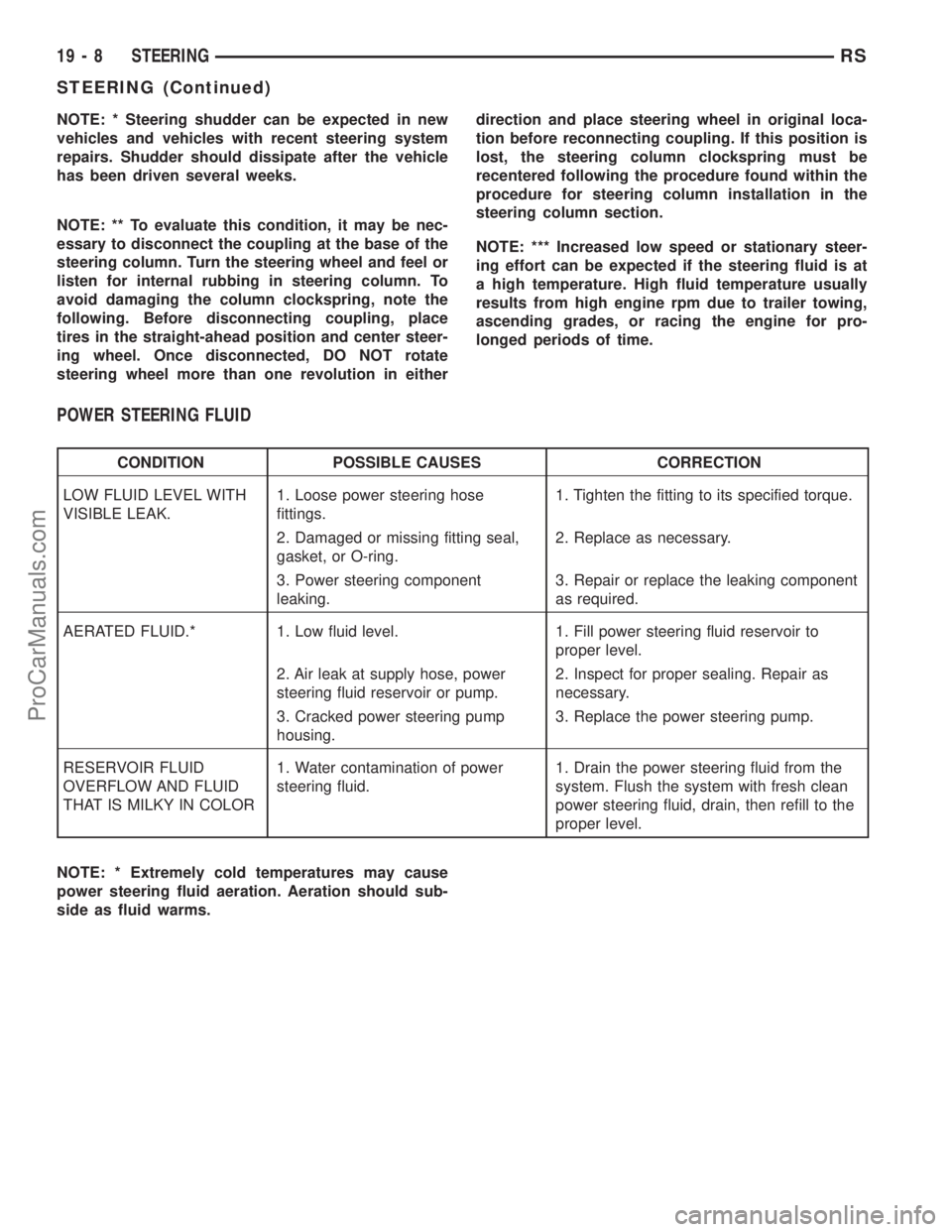
NOTE: * Steering shudder can be expected in new
vehicles and vehicles with recent steering system
repairs. Shudder should dissipate after the vehicle
has been driven several weeks.
NOTE: ** To evaluate this condition, it may be nec-
essary to disconnect the coupling at the base of the
steering column. Turn the steering wheel and feel or
listen for internal rubbing in steering column. To
avoid damaging the column clockspring, note the
following. Before disconnecting coupling, place
tires in the straight-ahead position and center steer-
ing wheel. Once disconnected, DO NOT rotate
steering wheel more than one revolution in eitherdirection and place steering wheel in original loca-
tion before reconnecting coupling. If this position is
lost, the steering column clockspring must be
recentered following the procedure found within the
procedure for steering column installation in the
steering column section.
NOTE: *** Increased low speed or stationary steer-
ing effort can be expected if the steering fluid is at
a high temperature. High fluid temperature usually
results from high engine rpm due to trailer towing,
ascending grades, or racing the engine for pro-
longed periods of time.
POWER STEERING FLUID
CONDITION POSSIBLE CAUSES CORRECTION
LOW FLUID LEVEL WITH
VISIBLE LEAK.1. Loose power steering hose
fittings.1. Tighten the fitting to its specified torque.
2. Damaged or missing fitting seal,
gasket, or O-ring.2. Replace as necessary.
3. Power steering component
leaking.3. Repair or replace the leaking component
as required.
AERATED FLUID.* 1. Low fluid level. 1. Fill power steering fluid reservoir to
proper level.
2. Air leak at supply hose, power
steering fluid reservoir or pump.2. Inspect for proper sealing. Repair as
necessary.
3. Cracked power steering pump
housing.3. Replace the power steering pump.
RESERVOIR FLUID
OVERFLOW AND FLUID
THAT IS MILKY IN COLOR1. Water contamination of power
steering fluid.1. Drain the power steering fluid from the
system. Flush the system with fresh clean
power steering fluid, drain, then refill to the
proper level.
NOTE: * Extremely cold temperatures may cause
power steering fluid aeration. Aeration should sub-
side as fluid warms.
19 - 8 STEERINGRS
STEERING (Continued)
ProCarManuals.com
Page 2173 of 2177
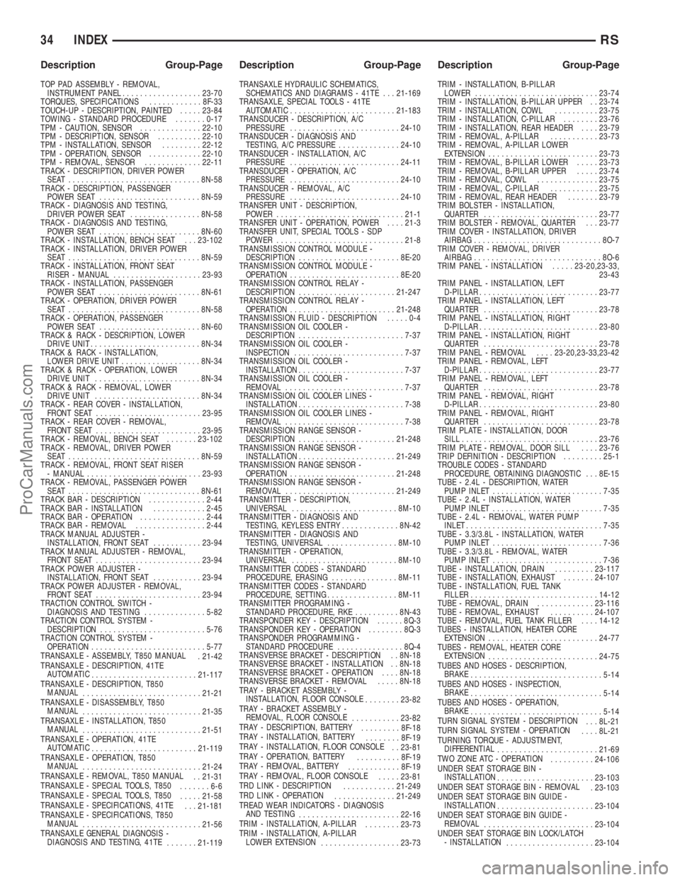
TOP PAD ASSEMBLY - REMOVAL,
INSTRUMENT PANEL..................23-70
TORQUES, SPECIFICATIONS............8F-33
TOUCH-UP - DESCRIPTION, PAINTED.....23-84
TOWING - STANDARD PROCEDURE.......0-17
TPM - CAUTION, SENSOR..............22-10
TPM - DESCRIPTION, SENSOR..........22-10
TPM - INSTALLATION, SENSOR.........22-12
TPM - OPERATION, SENSOR............22-10
TPM - REMOVAL, SENSOR.............22-11
TRACK - DESCRIPTION, DRIVER POWER
SEAT ..............................8N-58
TRACK - DESCRIPTION, PASSENGER
POWER SEAT.......................8N-59
TRACK - DIAGNOSIS AND TESTING,
DRIVER POWER SEAT................8N-58
TRACK - DIAGNOSIS AND TESTING,
POWER SEAT.......................8N-60
TRACK - INSTALLATION, BENCH SEAT . . . 23-102
TRACK - INSTALLATION, DRIVER POWER
SEAT ..............................8N-59
TRACK - INSTALLATION, FRONT SEAT
RISER - MANUAL....................23-93
TRACK - INSTALLATION, PASSENGER
POWER SEAT.......................8N-61
TRACK - OPERATION, DRIVER POWER
SEAT ..............................8N-58
TRACK - OPERATION, PASSENGER
POWER SEAT.......................8N-60
TRACK & RACK - DESCRIPTION, LOWER
DRIVE UNIT..........................8N-34
TRACK & RACK - INSTALLATION,
LOWER DRIVE UNIT..................8N-34
TRACK & RACK - OPERATION, LOWER
DRIVE UNIT........................8N-34
TRACK & RACK - REMOVAL, LOWER
DRIVE UNIT........................8N-34
TRACK - REAR COVER - INSTALLATION,
FRONT SEAT........................23-95
TRACK - REAR COVER - REMOVAL,
FRONT SEAT........................23-95
TRACK - REMOVAL, BENCH SEAT.......23-102
TRACK - REMOVAL, DRIVER POWER
SEAT ..............................8N-59
TRACK - REMOVAL, FRONT SEAT RISER
- MANUAL..........................23-93
TRACK - REMOVAL, PASSENGER POWER
SEAT ..............................8N-61
TRACK BAR - DESCRIPTION.............2-44
TRACK BAR - INSTALLATION............2-45
TRACK BAR - OPERATION...............2-44
TRACK BAR - REMOVAL................2-44
TRACK MANUAL ADJUSTER -
INSTALLATION, FRONT SEAT...........23-94
TRACK MANUAL ADJUSTER - REMOVAL,
FRONT SEAT........................23-94
TRACK POWER ADJUSTER -
INSTALLATION, FRONT SEAT...........23-94
TRACK POWER ADJUSTER - REMOVAL,
FRONT SEAT........................23-94
TRACTION CONTROL SWITCH -
DIAGNOSIS AND TESTING..............5-82
TRACTION CONTROL SYSTEM -
DESCRIPTION........................5-76
TRACTION CONTROL SYSTEM -
OPERATION..........................5-77
TRANSAXLE - ASSEMBLY, T850 MANUAL
. 21-42
TRANSAXLE - DESCRIPTION, 41TE
AUTOMATIC
........................21-117
TRANSAXLE - DESCRIPTION, T850
MANUAL
...........................21-21
TRANSAXLE - DISASSEMBLY, T850
MANUAL
...........................21-35
TRANSAXLE - INSTALLATION, T850
MANUAL
...........................21-51
TRANSAXLE - OPERATION, 41TE
AUTOMATIC
........................21-119
TRANSAXLE - OPERATION, T850
MANUAL
...........................21-24
TRANSAXLE - REMOVAL, T850 MANUAL
. . 21-31
TRANSAXLE - SPECIAL TOOLS, T850
.......6-6
TRANSAXLE - SPECIAL TOOLS, T850
.....21-58
TRANSAXLE - SPECIFICATIONS, 41TE
. . . 21-181
TRANSAXLE - SPECIFICATIONS, T850
MANUAL
...........................21-56
TRANSAXLE GENERAL DIAGNOSIS -
DIAGNOSIS AND TESTING, 41TE
.......21-119TRANSAXLE HYDRAULIC SCHEMATICS,
SCHEMATICS AND DIAGRAMS - 41TE . . . 21-169
TRANSAXLE, SPECIAL TOOLS - 41TE
AUTOMATIC........................21-183
TRANSDUCER - DESCRIPTION, A/C
PRESSURE.........................24-10
TRANSDUCER - DIAGNOSIS AND
TESTING, A/C PRESSURE..............24-10
TRANSDUCER - INSTALLATION, A/C
PRESSURE.........................24-11
TRANSDUCER - OPERATION, A/C
PRESSURE.........................24-10
TRANSDUCER - REMOVAL, A/C
PRESSURE.........................24-10
TRANSFER UNIT - DESCRIPTION,
POWER.............................21-1
TRANSFER UNIT - OPERATION, POWER....21-3
TRANSFER UNIT, SPECIAL TOOLS - SDP
POWER.............................21-8
TRANSMISSION CONTROL MODULE -
DESCRIPTION.......................8E-20
TRANSMISSION CONTROL MODULE -
OPERATION.........................8E-20
TRANSMISSION CONTROL RELAY -
DESCRIPTION......................21-247
TRANSMISSION CONTROL RELAY -
OPERATION........................21-248
TRANSMISSION FLUID - DESCRIPTION.....0-4
TRANSMISSION OIL COOLER -
DESCRIPTION........................7-37
TRANSMISSION OIL COOLER -
INSPECTION.........................7-37
TRANSMISSION OIL COOLER -
INSTALLATION........................7-37
TRANSMISSION OIL COOLER -
REMOVAL...........................7-37
TRANSMISSION OIL COOLER LINES -
INSTALLATION........................7-38
TRANSMISSION OIL COOLER LINES -
REMOVAL...........................7-38
TRANSMISSION RANGE SENSOR -
DESCRIPTION......................21-248
TRANSMISSION RANGE SENSOR -
INSTALLATION......................21-249
TRANSMISSION RANGE SENSOR -
OPERATION........................21-248
TRANSMISSION RANGE SENSOR -
REMOVAL.........................21-249
TRANSMITTER - DESCRIPTION,
UNIVERSAL........................8M-10
TRANSMITTER - DIAGNOSIS AND
TESTING, KEYLESS ENTRY.............8N-42
TRANSMITTER - DIAGNOSIS AND
TESTING, UNIVERSAL................8M-10
TRANSMITTER - OPERATION,
UNIVERSAL........................8M-10
TRANSMITTER CODES - STANDARD
PROCEDURE, ERASING...............8M-11
TRANSMITTER CODES - STANDARD
PROCEDURE, SETTING................8M-11
TRANSMITTER PROGRAMING -
STANDARD PROCEDURE, RKE..........8N-43
TRANSPONDER KEY - DESCRIPTION......8Q-3
TRANSPONDER KEY - OPERATION........8Q-3
TRANSPONDER PROGRAMMING -
STANDARD PROCEDURE...............8Q-4
TRANSVERSE BRACKET - DESCRIPTION . . 8N-18
TRANSVERSE BRACKET - INSTALLATION . . 8N-18
TRANSVERSE BRACKET - OPERATION....8N-18
TRANSVERSE BRACKET - REMOVAL.....8N-18
TRAY - BRACKET ASSEMBLY -
INSTALLATION, FLOOR CONSOLE
........23-82
TRAY - BRACKET ASSEMBLY -
REMOVAL, FLOOR CONSOLE
...........23-82
TRAY - DESCRIPTION, BATTERY
.........8F-18
TRAY - INSTALLATION, BATTERY
........8F-19
TRAY - INSTALLATION, FLOOR CONSOLE
. . 23-81
TRAY - OPERATION, BATTERY
..........8F-19
TRAY - REMOVAL, BATTERY
............8F-19
TRAY - REMOVAL, FLOOR CONSOLE
.....23-81
TRD LINK - DESCRIPTION
............21-249
TRD LINK - OPERATION
..............21-249
TREAD WEAR INDICATORS - DIAGNOSIS
AND TESTING
.......................22-16
TRIM - INSTALLATION, A-PILLAR
........23-73
TRIM - INSTALLATION, A-PILLAR
LOWER EXTENSION
..................23-73TRIM - INSTALLATION, B-PILLAR
LOWER............................23-74
TRIM - INSTALLATION, B-PILLAR UPPER . . 23-74
TRIM - INSTALLATION, COWL..........23-75
TRIM - INSTALLATION, C-PILLAR........23-76
TRIM - INSTALLATION, REAR HEADER....23-79
TRIM - REMOVAL, A-PILLAR...........23-73
TRIM - REMOVAL, A-PILLAR LOWER
EXTENSION.........................23-73
TRIM - REMOVAL, B-PILLAR LOWER.....23-73
TRIM - REMOVAL, B-PILLAR UPPER.....23-74
TRIM - REMOVAL, COWL..............23-75
TRIM - REMOVAL, C-PILLAR...........23-75
TRIM - REMOVAL, REAR HEADER.......23-79
TRIM BOLSTER - INSTALLATION,
QUARTER..........................23-77
TRIM BOLSTER - REMOVAL, QUARTER . . . 23-77
TRIM COVER - INSTALLATION, DRIVER
AIRBAG.............................8O-7
TRIM COVER - REMOVAL, DRIVER
AIRBAG.............................8O-6
TRIM PANEL - INSTALLATION.....23-20,23-33,
23-43
TRIM PANEL - INSTALLATION, LEFT
D-PILLAR...........................23-77
TRIM PANEL - INSTALLATION, LEFT
QUARTER..........................23-78
TRIM PANEL - INSTALLATION, RIGHT
D-PILLAR...........................23-80
TRIM PANEL - INSTALLATION, RIGHT
QUARTER..........................23-78
TRIM PANEL - REMOVAL....23-20,23-33,23-42
TRIM PANEL - REMOVAL, LEFT
D-PILLAR...........................23-77
TRIM PANEL - REMOVAL, LEFT
QUARTER..........................23-78
TRIM PANEL - REMOVAL, RIGHT
D-PILLAR...........................23-80
TRIM PANEL - REMOVAL, RIGHT
QUARTER..........................23-78
TRIM PLATE - INSTALLATION, DOOR
SILL...............................23-76
TRIM PLATE - REMOVAL, DOOR SILL....23-76
TRIP DEFINITION - DESCRIPTION.........25-1
TROUBLE CODES - STANDARD
PROCEDURE, OBTAINING DIAGNOSTIC . . . 8E-15
TUBE - 2.4L - DESCRIPTION, WATER
PUMP INLET.........................7-35
TUBE - 2.4L - INSTALLATION, WATER
PUMP INLET.........................7-35
TUBE - 2.4L - REMOVAL, WATER PUMP
INLET...............................7-35
TUBE - 3.3/3.8L - INSTALLATION, WATER
PUMP INLET.........................7-36
TUBE - 3.3/3.8L - REMOVAL, WATER
PUMP INLET.........................7-36
TUBE - INSTALLATION, DRAIN.........23-117
TUBE - INSTALLATION, EXHAUST.......24-107
TUBE - INSTALLATION, FUEL TANK
FILLER.............................14-12
TUBE - REMOVAL, DRAIN.............23-116
TUBE - REMOVAL, EXHAUST..........24-107
TUBE - REMOVAL, FUEL TANK FILLER....14-12
TUBES - INSTALLATION, HEATER CORE
EXTENSION.........................24-77
TUBES - REMOVAL, HEATER CORE
EXTENSION
.........................24-75
TUBES AND HOSES - DESCRIPTION,
BRAKE
..............................5-14
TUBES AND HOSES - INSPECTION,
BRAKE
..............................5-14
TUBES AND HOSES - OPERATION,
BRAKE
..............................5-14
TURN SIGNAL SYSTEM - DESCRIPTION
. . . 8L-21
TURN SIGNAL SYSTEM - OPERATION
....8L-21
TURNING TORQUE - ADJUSTMENT,
DIFFERENTIAL
.......................21-69
TWO ZONE ATC - OPERATION
..........24-106
UNDER SEAT STORAGE BIN -
INSTALLATION
......................23-103
UNDER SEAT STORAGE BIN - REMOVAL
. 23-103
UNDER SEAT STORAGE BIN GUIDE -
INSTALLATION
......................23-104
UNDER SEAT STORAGE BIN GUIDE -
REMOVAL
.........................23-104
UNDER SEAT STORAGE BIN LOCK/LATCH
- INSTALLATION
....................23-104
34 INDEXRS
Description Group-Page Description Group-Page Description Group-Page
ProCarManuals.com