engine oil CHRYSLER CARAVAN 2003 Owner's Manual
[x] Cancel search | Manufacturer: CHRYSLER, Model Year: 2003, Model line: CARAVAN, Model: CHRYSLER CARAVAN 2003Pages: 2177, PDF Size: 59.81 MB
Page 37 of 2177
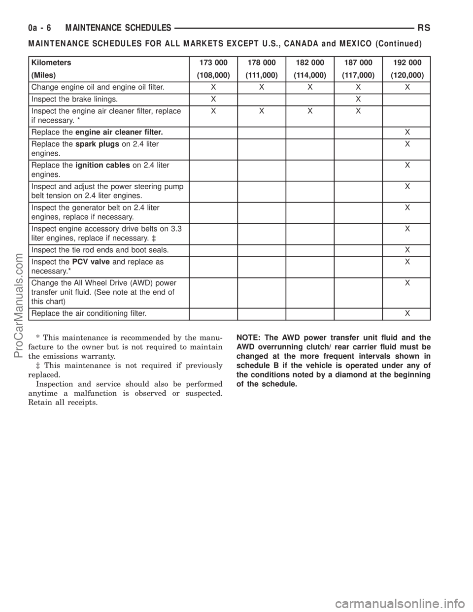
Kilometers 173 000 178 000 182 000 187 000 192 000
(Miles) (108,000) (111,000) (114,000) (117,000) (120,000)
Change engine oil and engine oil filter.XXXX X
Inspect the brake linings. X X
Inspect the engine air cleaner filter, replace
if necessary. *XXXX
Replace theengine air cleaner filter.X
Replace thespark plugson 2.4 liter
engines.X
Replace theignition cableson 2.4 liter
engines.X
Inspect and adjust the power steering pump
belt tension on 2.4 liter engines.X
Inspect the generator belt on 2.4 liter
engines, replace if necessary.X
Inspect engine accessory drive belts on 3.3
liter engines, replace if necessary. ³X
Inspect the tie rod ends and boot seals. X
Inspect thePCV valveand replace as
necessary.*X
Change the All Wheel Drive (AWD) power
transfer unit fluid. (See note at the end of
this chart)X
Replace the air conditioning filter.X
* This maintenance is recommended by the manu-
facture to the owner but is not required to maintain
the emissions warranty.
³ This maintenance is not required if previously
replaced.
Inspection and service should also be performed
anytime a malfunction is observed or suspected.
Retain all receipts.NOTE: The AWD power transfer unit fluid and the
AWD overrunning clutch/ rear carrier fluid must be
changed at the more frequent intervals shown in
schedule B if the vehicle is operated under any of
the conditions noted by a diamond at the beginning
of the schedule.
0a - 6 MAINTENANCE SCHEDULESRS
MAINTENANCE SCHEDULES FOR ALL MARKETS EXCEPT U.S., CANADA and MEXICO (Continued)
ProCarManuals.com
Page 38 of 2177
![CHRYSLER CARAVAN 2003 Owners Manual SCHEDULE ªAº
Kilometers 12 000 24 000 36 000 48 000 60 000 72 000
(Miles) (7,500) (15,000) (22,500 (30,000) (37,500) (45,000)
[Months] [6] [12] [18] [24] [30] [36]
Change engine oil and engine oil
f CHRYSLER CARAVAN 2003 Owners Manual SCHEDULE ªAº
Kilometers 12 000 24 000 36 000 48 000 60 000 72 000
(Miles) (7,500) (15,000) (22,500 (30,000) (37,500) (45,000)
[Months] [6] [12] [18] [24] [30] [36]
Change engine oil and engine oil
f](/img/25/56863/w960_56863-37.png)
SCHEDULE ªAº
Kilometers 12 000 24 000 36 000 48 000 60 000 72 000
(Miles) (7,500) (15,000) (22,500 (30,000) (37,500) (45,000)
[Months] [6] [12] [18] [24] [30] [36]
Change engine oil and engine oil
filter.XXXXX X
Inspect the brake linings. X X
Inspect the engine air cleaner filter,
replace if necessary. *XXX X X
Replace theengine air cleaner
filter.X
Replace thespark plugson 2.4 liter
engines.X
Inspect the tie rod ends and boot
seals.X
Replace the air conditioning filter. X X X
Kilometers 84 000 96 000 108 000 120 000 132 000 144 000
(Miles) (52,500) (60,000) (67,500) (75,000) (82,500) (90,000)
[Months] [42] [48] [54] [60] [66] [72]
Change engine oil and engine oil filter.XXXXX X
Inspect the brake linings. X X
Inspect the engine air cleaner filter,
replace if necessary. *X XXX
Replace theengine air cleaner filter.XX
Replace thespark plugson 2.4 liter
engines.XX
Replace theignition cableson 2.4 liter
engines.X
Inspect and adjust the power steering
pump belt tension on 2.4 liter engines.XX
Inspect the tie rod ends and boot seals. X X
Inspect the generator belt on 2.4 liter
engines, replace if necessary.XX
Check thePCV valveand replace, if
necessary.*XX
Inspect the serpentine drive belt on 3.3
liter engines, replace if necessary. ³XX X
Flush and replace the engine coolant at
60 months, regardless of mileage.X
Replace the air conditioning filter. X X X
RSMAINTENANCE SCHEDULES0a-7
MAINTENANCE SCHEDULES FOR ALL MARKETS EXCEPT U.S., CANADA and MEXICO (Continued)
ProCarManuals.com
Page 39 of 2177
![CHRYSLER CARAVAN 2003 Owners Manual Kilometers 156 000 160 000 168 000 180 000 192 000
(Miles) (97,500) (100,000) (105,000) (112,500) (120,000)
[Months] [78] [84] [90] [96]
Change engine oil and engine oil filter. X X X X
Inspect the br CHRYSLER CARAVAN 2003 Owners Manual Kilometers 156 000 160 000 168 000 180 000 192 000
(Miles) (97,500) (100,000) (105,000) (112,500) (120,000)
[Months] [78] [84] [90] [96]
Change engine oil and engine oil filter. X X X X
Inspect the br](/img/25/56863/w960_56863-38.png)
Kilometers 156 000 160 000 168 000 180 000 192 000
(Miles) (97,500) (100,000) (105,000) (112,500) (120,000)
[Months] [78] [84] [90] [96]
Change engine oil and engine oil filter. X X X X
Inspect the brake linings. X
Inspect the engine air cleaner filter, replace
if necessary. *XXXX
Replace theengine air cleaner filter.X
Replace thespark plugson 2.4 liter
engines.X
Replace theignition cableson 2.4 liter
engines.X
Inspect the tie rod ends and boot seals. X
Inspect and adjust the power steering pump
belt tension on 2.4 liter engines.XX
Inspect the generator belt on 2.4 liter
engines, replace if necessary.XX
Check and replace thePCV valve,if
necessary.*X
Inspect the serpentine drive belt on 3.3 liter
engines, replace if necessary. ³XX
Replace thespark plugs3.3 liter engines. X
Replace theignition cables3.3 liter
engines.X
Flush and replace the engine coolant at
100,000 miles, if not done at 60 months.X
Replace theengine timing belton 2.4 liter
engines only.X
Replace the air conditioning filter. X
* This maintenance is recommended by the manu-
facture to the owner but is not required to maintain
the emissions warranty.
³ This maintenance is not required if previously
replaced.
Inspection and service should also be performed
anytime a malfunction is observed or suspected.
Retain all receipts.WARNING: You can be badly injured working on or
around a motor vehicle. Do only that service work
for which you have the knowledge and the right
equipment. If you have any doubt about your ability
to perform a service job, take your vehicle to a
competent mechanic.
0a - 8 MAINTENANCE SCHEDULESRS
MAINTENANCE SCHEDULES FOR ALL MARKETS EXCEPT U.S., CANADA and MEXICO (Continued)
ProCarManuals.com
Page 40 of 2177
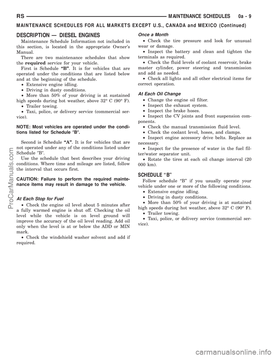
DESCRIPTION Ð DIESEL ENGINES
Maintenance Schedule Information not included in
this section, is located in the appropriate Owner's
Manual.
There are two maintenance schedules that show
therequiredservice for your vehicle.
First is ScheduleªBº. It is for vehicles that are
operated under the conditions that are listed below
and at the beginning of the schedule.
²Extensive engine idling.
²Driving in dusty conditions.
²More than 50% of your driving is at sustained
high speeds during hot weather, above 32É C (90É F).
²Trailer towing.
²Taxi, police, or delivery service (commercial ser-
vice).
NOTE: Most vehicles are operated under the condi-
tions listed for Schedule(B(.
Second is ScheduleªAº. It is for vehicles that are
not operated under any of the conditions listed under
Schedule9B9.
Use the schedule that best describes your driving
conditions. Where time and mileage are listed, follow
the interval that occurs first.
CAUTION: Failure to perform the required mainte-
nance items may result in damage to the vehicle.
At Each Stop for Fuel
²Check the engine oil level about 5 minutes after
a fully warmed engine is shut off. Checking the oil
level while the vehicle is on level ground will
improve the accuracy of the oil level reading. Add oil
only when the level is at or below the ADD or MIN
mark.
²Check the windshield washer solvent and add if
required.
Once a Month
²Check the tire pressure and look for unusual
wear or damage.
²Inspect the battery and clean and tighten the
terminals as required.
²Check the fluid levels of coolant reservoir, brake
master cylinder, power steering and transmission
and add as needed.
²Check all lights and all other electrical items for
correct operation.
At Each Oil Change
²Change the engine oil filter.
²Inspect the exhaust system.
²Inspect the brake hoses.
²Inspect the CV joints and front suspension com-
ponents.
²Check the manual transmission fluid level.
²Check the coolant level, hoses, and clamps.
²Inspect engine accessory drive belts. Replace as
necessary.
²Inspect for the presence of water in the fuel fil-
ter/water separator unit.
²Rotate the tires at each oil change interval (20
000 km).
SCHEDULE ªBº
Follow schedule ªBº if you usually operate your
vehicle under one or more of the following conditions.
²Extensive engine idling.
²Driving in dusty conditions.
²More than 50% of your driving is at sustained
high speeds during hot weather, above 32É C (90É F).
²Trailer towing.
²Taxi, police, or delivery service (commercial ser-
vice).
RSMAINTENANCE SCHEDULES0a-9
MAINTENANCE SCHEDULES FOR ALL MARKETS EXCEPT U.S., CANADA and MEXICO (Continued)
ProCarManuals.com
Page 41 of 2177
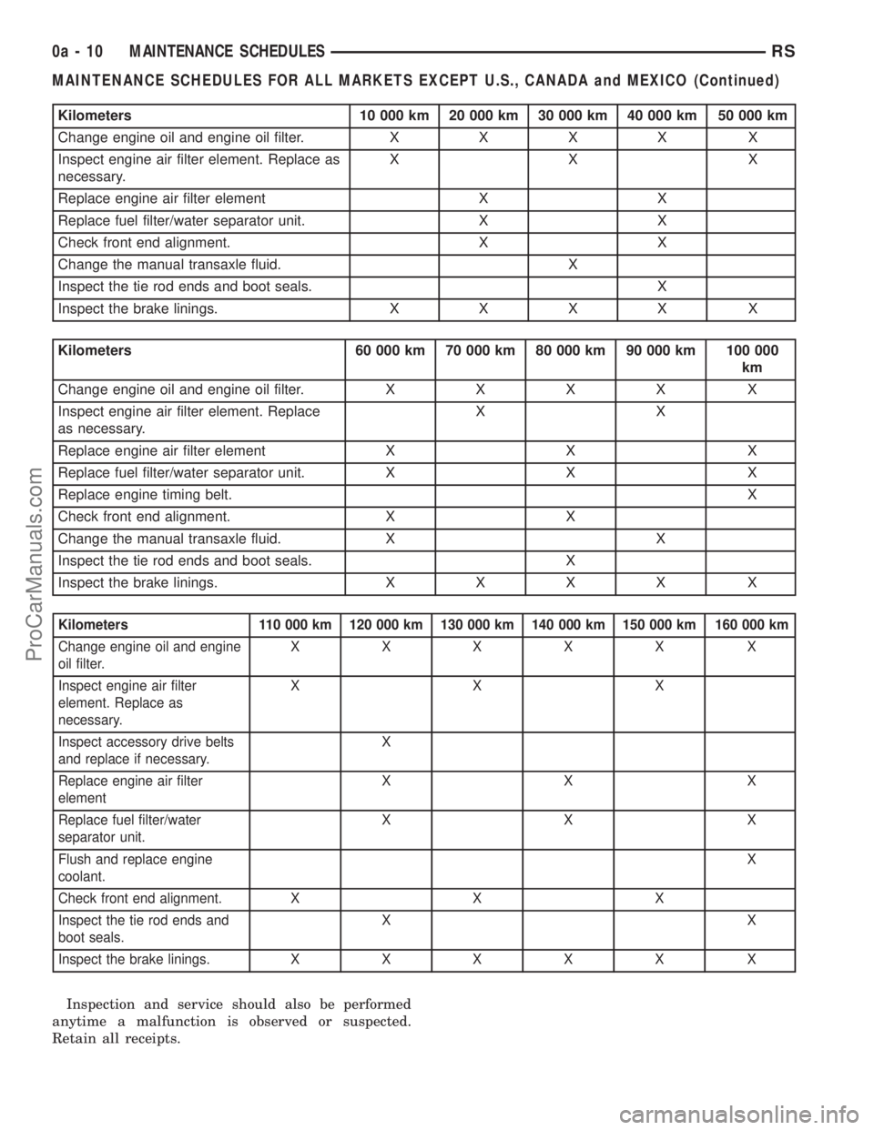
Kilometers 10 000 km 20 000 km 30 000 km 40 000 km 50 000 km
Change engine oil and engine oil filter.XXXX X
Inspect engine air filter element. Replace as
necessary.XX X
Replace engine air filter element X X
Replace fuel filter/water separator unit. X X
Check front end alignment. X X
Change the manual transaxle fluid. X
Inspect the tie rod ends and boot seals. X
Inspect the brake linings.XXXX X
Kilometers 60 000 km 70 000 km 80 000 km 90 000 km 100 000
km
Change engine oil and engine oil filter.XXXX X
Inspect engine air filter element. Replace
as necessary.XX
Replace engine air filter element X X X
Replace fuel filter/water separator unit. X X X
Replace engine timing belt.X
Check front end alignment. X X
Change the manual transaxle fluid. X X
Inspect the tie rod ends and boot seals. X
Inspect the brake linings.XXXX X
Kilometers 110 000 km 120 000 km 130 000 km 140 000 km 150 000 km 160 000 km
Change engine oil and engine
oil filter.XXXXX X
Inspect engine air filter
element. Replace as
necessary.XXX
Inspect accessory drive belts
and replace if necessary.X
Replace engine air filter
elementXX X
Replace fuel filter/water
separator unit.XX X
Flush and replace engine
coolant.X
Check front end alignment. X X X
Inspect the tie rod ends and
boot seals.XX
Inspect the brake linings.XXXXX X
Inspection and service should also be performed
anytime a malfunction is observed or suspected.
Retain all receipts.
0a - 10 MAINTENANCE SCHEDULESRS
MAINTENANCE SCHEDULES FOR ALL MARKETS EXCEPT U.S., CANADA and MEXICO (Continued)
ProCarManuals.com
Page 42 of 2177
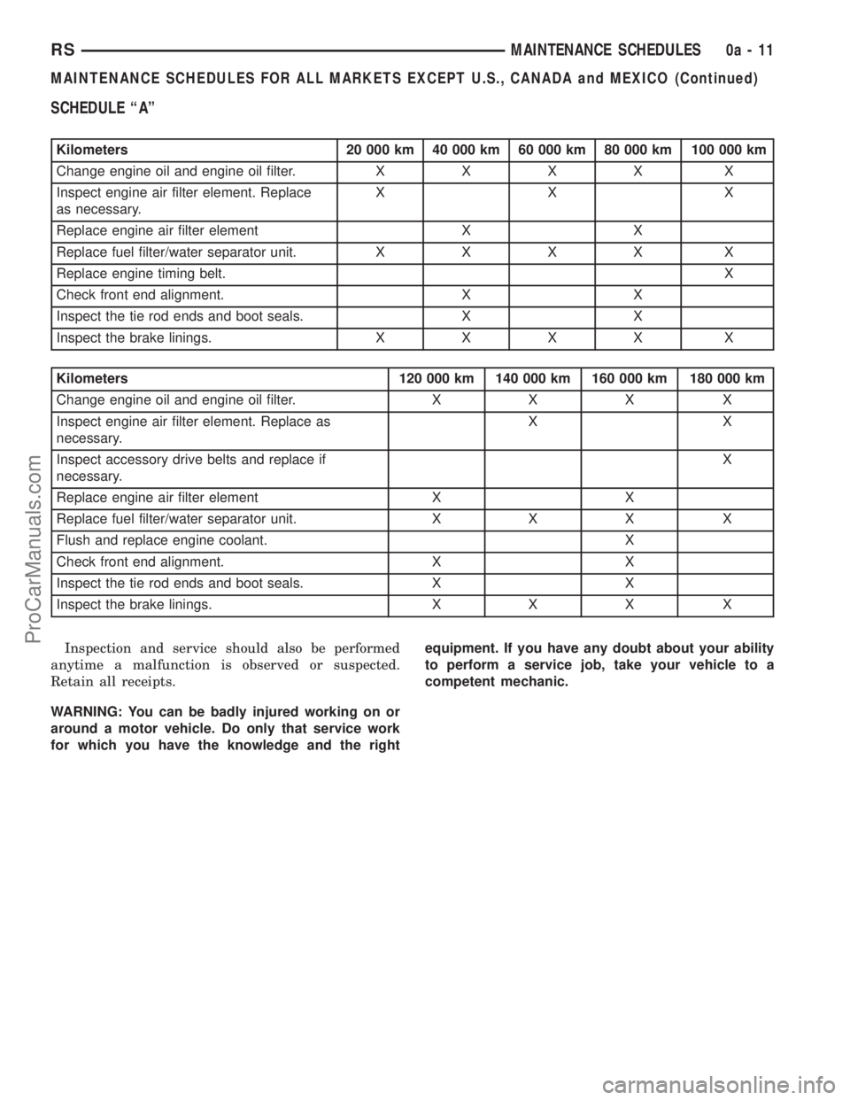
SCHEDULE ªAº
Kilometers 20 000 km 40 000 km 60 000 km 80 000 km 100 000 km
Change engine oil and engine oil filter.XXXX X
Inspect engine air filter element. Replace
as necessary.XX X
Replace engine air filter element X X
Replace fuel filter/water separator unit.XXXX X
Replace engine timing belt.X
Check front end alignment. X X
Inspect the tie rod ends and boot seals. X X
Inspect the brake linings.XXXX X
Kilometers 120 000 km 140 000 km 160 000 km 180 000 km
Change engine oil and engine oil filter. X X X X
Inspect engine air filter element. Replace as
necessary.XX
Inspect accessory drive belts and replace if
necessary.X
Replace engine air filter element X X
Replace fuel filter/water separator unit. X X X X
Flush and replace engine coolant. X
Check front end alignment. X X
Inspect the tie rod ends and boot seals. X X
Inspect the brake linings. X X X X
Inspection and service should also be performed
anytime a malfunction is observed or suspected.
Retain all receipts.
WARNING: You can be badly injured working on or
around a motor vehicle. Do only that service work
for which you have the knowledge and the rightequipment. If you have any doubt about your ability
to perform a service job, take your vehicle to a
competent mechanic.
RSMAINTENANCE SCHEDULES0a-11
MAINTENANCE SCHEDULES FOR ALL MARKETS EXCEPT U.S., CANADA and MEXICO (Continued)
ProCarManuals.com
Page 161 of 2177
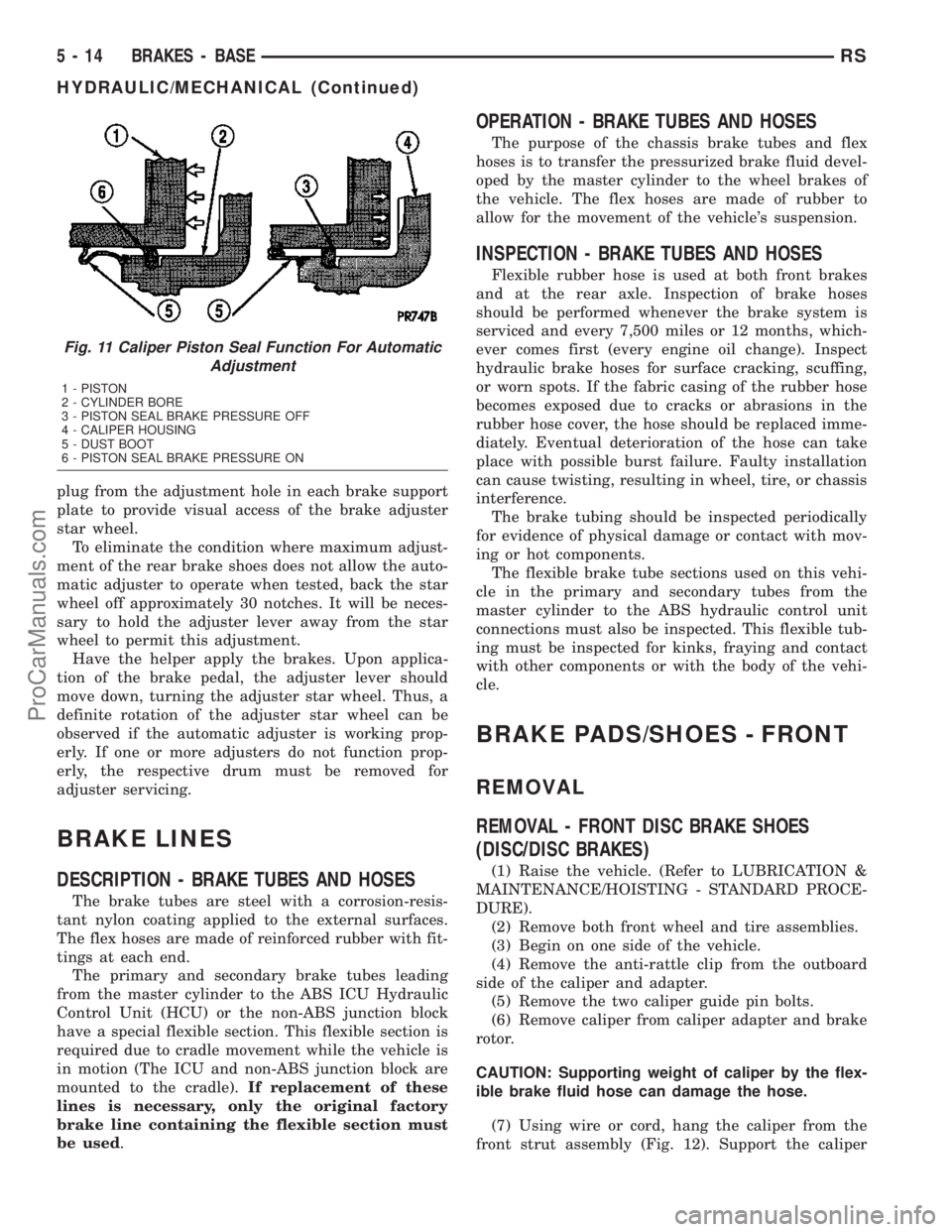
plug from the adjustment hole in each brake support
plate to provide visual access of the brake adjuster
star wheel.
To eliminate the condition where maximum adjust-
ment of the rear brake shoes does not allow the auto-
matic adjuster to operate when tested, back the star
wheel off approximately 30 notches. It will be neces-
sary to hold the adjuster lever away from the star
wheel to permit this adjustment.
Have the helper apply the brakes. Upon applica-
tion of the brake pedal, the adjuster lever should
move down, turning the adjuster star wheel. Thus, a
definite rotation of the adjuster star wheel can be
observed if the automatic adjuster is working prop-
erly. If one or more adjusters do not function prop-
erly, the respective drum must be removed for
adjuster servicing.
BRAKE LINES
DESCRIPTION - BRAKE TUBES AND HOSES
The brake tubes are steel with a corrosion-resis-
tant nylon coating applied to the external surfaces.
The flex hoses are made of reinforced rubber with fit-
tings at each end.
The primary and secondary brake tubes leading
from the master cylinder to the ABS ICU Hydraulic
Control Unit (HCU) or the non-ABS junction block
have a special flexible section. This flexible section is
required due to cradle movement while the vehicle is
in motion (The ICU and non-ABS junction block are
mounted to the cradle).If replacement of these
lines is necessary, only the original factory
brake line containing the flexible section must
be used.
OPERATION - BRAKE TUBES AND HOSES
The purpose of the chassis brake tubes and flex
hoses is to transfer the pressurized brake fluid devel-
oped by the master cylinder to the wheel brakes of
the vehicle. The flex hoses are made of rubber to
allow for the movement of the vehicle's suspension.
INSPECTION - BRAKE TUBES AND HOSES
Flexible rubber hose is used at both front brakes
and at the rear axle. Inspection of brake hoses
should be performed whenever the brake system is
serviced and every 7,500 miles or 12 months, which-
ever comes first (every engine oil change). Inspect
hydraulic brake hoses for surface cracking, scuffing,
or worn spots. If the fabric casing of the rubber hose
becomes exposed due to cracks or abrasions in the
rubber hose cover, the hose should be replaced imme-
diately. Eventual deterioration of the hose can take
place with possible burst failure. Faulty installation
can cause twisting, resulting in wheel, tire, or chassis
interference.
The brake tubing should be inspected periodically
for evidence of physical damage or contact with mov-
ing or hot components.
The flexible brake tube sections used on this vehi-
cle in the primary and secondary tubes from the
master cylinder to the ABS hydraulic control unit
connections must also be inspected. This flexible tub-
ing must be inspected for kinks, fraying and contact
with other components or with the body of the vehi-
cle.
BRAKE PADS/SHOES - FRONT
REMOVAL
REMOVAL - FRONT DISC BRAKE SHOES
(DISC/DISC BRAKES)
(1) Raise the vehicle. (Refer to LUBRICATION &
MAINTENANCE/HOISTING - STANDARD PROCE-
DURE).
(2) Remove both front wheel and tire assemblies.
(3) Begin on one side of the vehicle.
(4) Remove the anti-rattle clip from the outboard
side of the caliper and adapter.
(5) Remove the two caliper guide pin bolts.
(6) Remove caliper from caliper adapter and brake
rotor.
CAUTION: Supporting weight of caliper by the flex-
ible brake fluid hose can damage the hose.
(7) Using wire or cord, hang the caliper from the
front strut assembly (Fig. 12). Support the caliper
Fig. 11 Caliper Piston Seal Function For Automatic
Adjustment
1 - PISTON
2 - CYLINDER BORE
3 - PISTON SEAL BRAKE PRESSURE OFF
4 - CALIPER HOUSING
5 - DUST BOOT
6 - PISTON SEAL BRAKE PRESSURE ON
5 - 14 BRAKES - BASERS
HYDRAULIC/MECHANICAL (Continued)
ProCarManuals.com
Page 180 of 2177
Use only brake fluid that was stored in a tightly-
sealed container.
DO NOTuse petroleum-based fluid because seal
damage will result. Petroleum based fluids would be
items such as engine oil, transmission fluid, power
steering fluid etc.
SPECIFICATIONS
BRAKE FLUID
The brake fluid used in this vehicle must conform
to DOT 3 specifications (DOT 4 and DOT 4+ are
acceptable) and SAE J1703 standards. No other type
of brake fluid is recommended or approved for usage
in the vehicle brake system. Use only MopartBrake
Fluid or equivalent from a tightly sealed container.
CAUTION: Never use reclaimed brake fluid or fluid
from an container which has been left open. An
open container of brake fluid will absorb moisture
from the air and contaminate the fluid.
CAUTION: Never use any type of a petroleum-based
fluid in the brake hydraulic system. Use of such
type fluids will result in seal damage of the vehicle
brake hydraulic system causing a failure of the
vehicle brake system. Petroleum based fluids would
be items such as engine oil, transmission fluid,
power steering fluid, etc.
JUNCTION BLOCK
DESCRIPTION - NON-ABS JUNCTION BLOCK
A junction block is used on vehicles that are not
equipped with antilock brakes (ABS). The junction
block mounts in the same location as the integrated
control unit (ICU) does on vehicles equipped with
ABS. This allows for use of the same brake tube con-
figuration on all vehicles. The junction block is
located on the driver's side of the front suspension
cradle/crossmember below the master cylinder (Fig.
45).
It has six threaded ports to which the brake tubes
connect. Two are for the primary and secondary
brake tubes coming from the master cylinder. The
remaining four are for the chassis brake tubes going
to each brake assembly.
OPERATION - NON-ABS JUNCTION BLOCK
The junction block distributes the brake fluid com-
ing from the master cylinder primary and secondary
ports to the four chassis brake tubes leading to the
brakes at each wheel. Since the junction blockmounts in the same location as the ABS integrated
control unit (ICU), it allows for the common use of
brake tubes going to the brakes whether the vehicle
is equipped with or without ABS.
NOTE: Although the brake tubes coming from the
master cylinder to the junction block or ABS ICU
may appear to be the same, they are not. They are
unique to each brake system application.
REMOVAL - NON-ABS JUNCTION BLOCK
(1) Using a brake pedal depressor, move and lock
the brake pedal to a position past its first 1 inch of
travel. This will prevent brake fluid from draining
out of the master cylinder when the brake tubes are
removed from the junction block.
(2) Disconnect the battery negative cable.
(3) If the vehicle is equipped with speed control,
perform the following:
(a) Disconnect the battery positive cable.
(b) Remove the battery (Refer to 8 - ELECTRI-
CAL/BATTERY SYSTEM/BATTERY - REMOVAL).
(c) Disconnect the vacuum hose connector at the
tank built into the battery tray.
(d) Remove the screw securing the coolant filler
neck to the battery tray.
(e) Remove the battery tray (Refer to 8 - ELEC-
TRICAL/BATTERY SYSTEM/TRAY - REMOVAL).
(f) Remove the fasteners and move the speed
control servo off to the side, out of the way.
CAUTION: Before removing the brake tubes from
the junction block, the junction block and the brake
tubes must be thoroughly cleaned. This is required
to prevent contamination from entering the brake
hydraulic system.
(4) Remove the four chassis brake tubes from the
top of the junction block (Fig. 45).
(5) Remove the primary and secondary brake
tubes from the top of the junction block.
(6) Remove the bolts attaching the junction block
mounting bracket to the front suspension crossmem-
ber (Fig. 45), then remove the junction block.
INSTALLATION - NON-ABS JUNCTION BLOCK
(1) Install the junction block and mounting bracket
on the front suspension crossmember (Fig. 45).
Install the mounting bolts and tighten to a torque of
28 N´m (250 in. lbs.).
(2) Install the primary and secondary brake tubes
from the master cylinder in their ports. Tighten tube
nuts to a torque of 17 N´m (145 in. lbs.).Take care
not to twist tubes when tightening tube nuts.
They must be properly positioned to allow free
RSBRAKES - BASE5-33
FLUID (Continued)
ProCarManuals.com
Page 247 of 2177
SERVICE DIAGNOSIS - CLUTCH GRAB/CHATTER
CONDITION POSSIBLE CAUSES CORRECTION
CLUTCH DISC FACING
COVERED WITH OIL OR
GREASEOil leak at engine rear main or
transaxle input shaft seal.Correct leak and replace modular clutch
assembly (2.4L Gas) or clutch cover and disc
(2.5L TD).
Too much grease applied to splines
of disc and input shaft.Apply lighter coating of grease to splines.
NO FAULT FOUND WITH
CLUTCH
COMPONENTSProblem actually related to
suspension or driveline component.Further diagnosis required. Check engine/
transmission mounts, suspension attaching
parts and other driveline components as
needed.
Engine related problems. Check EFI and ignition systems.
PARTIAL ENGAGEMENT
OF CLUTCH DISCClutch cover, spring, or release
fingers bent, distorted (rough
handling, improper assembly).Replace modular clutch assembly (2.4L Gas)
or clutch cover and disc (2.5L TD).
Clutch disc damaged or distorted. Replace modular clutch assembly (2.4L Gas)
or clutch cover and disc (2.5L TD).
Clutch misalignment. Verify modular clutch pilot plate alignment to
crankshaft. Replace the modular clutch
assembly (2.4L Gas) or clutch cover and disc
(2.5L TD) if the pilot plate is loose or bent.
Improper transaxle-to-engine
installation.Verify transaxle is properly installed to
engine.
SERVICE DIAGNOSIS - CLUTCH SLIPS
CONDITION POSSIBLE CAUSES CORRECTION
DISC FACING WORN
OUTNormal wear. Replace modular clutch assembly (2.4L Gas)
or clutch cover and disc (2.5L TD).
Driver frequently rides (slips) clutch,
results in rapid wear, overheating.Replace modular clutch assembly (2.4L Gas)
or clutch cover and disc (2.5L TD).
Insufficient clutch cover diaphragm
spring tensionReplace modular clutch assembly (2.4L Gas)
or clutch cover and disc (2.5L TD).
CLUTCH DISC FACING
CONTAMINATED WITH
OIL OR GREASELeak at rear main oil seal or
transaxle input shaft sealReplace leaking seals. Replace modular
clutch assembly (2.4L Gas) or clutch cover
and disc (2.5L TD).
Excessive amount of grease applied
to input shaft splinesApply less grease to input shaft. Replace
modular clutch assembly (2.4L Gas) or clutch
cover and disc (2.5L TD).
Road splash, water entering housing Seal housing. Inspect clutch assembly.
CLUTCH IS RUNNING
PARTIALLY
DISENGAGEDRelease bearing sticking or binding,
does not return to normal running
position.Verify that bearing is actually binding. Then,
replace bearing and transmission front
bearing retainer if sleeve surface is
damaged.
Clutch pedal not returning to static
position.Inspect pedal assembly for damage and/or
obstructions. Replace componnents as
necessary.
Clutch master cylinder or pushrod
damaged causing high preload.Replace clutch master cylinder assembly.
Slave cylinder binding or stuck. Replace slave cylinder.
6 - 4 CLUTCHRS
CLUTCH (Continued)
ProCarManuals.com
Page 249 of 2177
DIAGNOSIS AND TESTING - DRIVE PLATE
MISALIGNMENT
Common causes of misalignment are:
²Heat warping
²Mounting drive plate on a dirty crankshaft
flange
²Incorrect bolt tightening
²Improper seating on the crankshaft shoulder
²Loose crankshaft bolts
Clean the crankshaft flange before mounting the
drive plate. Dirt and grease on the flange surface
may misalign the flywheel, causing excessive runout.
Use new bolts when mounting drive plate to crank-
shaft. Tighten drive plate bolts to specified torque
only. Over-tightening can distort the drive plate hub
causing excessive runout.
DIAGNOSIS AND TESTING - CLUTCH COVER
AND DISC RUNOUT
Check condition of the clutch cover before installa-
tion. A warped cover or diaphragm spring will cause
grab and/or incomplete release or engagement. Use
care when handling the clutch assembly. Impact can
distort the cover, diaphragm spring, and release fin-
gers.
DIAGNOSIS AND TESTING - CLUTCH CHATTER
COMPLAINTS
For all clutch chatter complaints, perform the fol-
lowing:
(1) Check for loose, misaligned, or broken engine
and transmission mounts. If present, they should be
corrected at this time. Test vehicle for chatter. If
chatter is gone, there is no need to go any further.
(2) If chatter persists, check hydraulic clutch
release system is functioning properly.
(3) Check for loose connections in drivetrain. Cor-
rect any problems and determine if clutch chatter
complaints have been satisfied. If not:
(a) Remove transaxle.
(b) Check to see if the release bearing is sticky
or binding. Replace bearing, if needed.
(c) Check linkage for excessive wear on the pivot
stud and fork fingers. Replace all worn parts.
(d) Check clutch assembly for contamination
(dirt, oil). Replace clutch assembly, if required.
(e) Check to see if the clutch disc hub splines
are damaged. Replace with new clutch assembly, if
necessary.
(f) Check input shaft splines for damage.
Replace, if necessary.
(g) Check for uneven wear on clutch fingers.
(h) Check for broken clutch cover diaphragm
spring fingers. Replace with new clutch assembly,
if necessary.
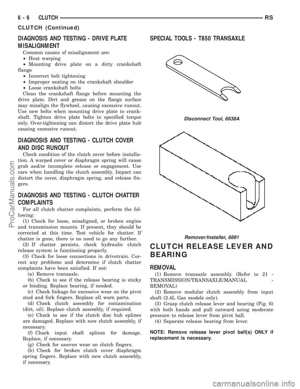
SPECIAL TOOLS - T850 TRANSAXLE
CLUTCH RELEASE LEVER AND
BEARING
REMOVAL
(1) Remove transaxle assembly. (Refer to 21 -
TRANSMISSION/TRANSAXLE/MANUAL -
REMOVAL)
(2) Remove modular clutch assembly from input
shaft (2.4L Gas models only).
(3) Grasp clutch release lever and bearing (Fig. 6)
with both hands and pull outward using moderate
pressure to release lever from pivot ball.
(4) Separate release bearing from lever.
NOTE: Remove release lever pivot ball(s) ONLY if
replacement is necessary.
Disconnect Tool, 6638A
Remover/Installer, 6891
6 - 6 CLUTCHRS
CLUTCH (Continued)
ProCarManuals.com