fuse diagram CHRYSLER CARAVAN 2003 Workshop Manual
[x] Cancel search | Manufacturer: CHRYSLER, Model Year: 2003, Model line: CARAVAN, Model: CHRYSLER CARAVAN 2003Pages: 2177, PDF Size: 59.81 MB
Page 2018 of 2177

DRBIIItscan tool to perform further diagnosis. Refer
to the appropriate diagnostic information.
TESTS
(1) Verify the battery state of charge. (Refer to 8 -
ELECTRICAL/BATTERY SYSTEM/BATTERY -
DIAGNOSIS AND TESTING).
(2) Connect an ammeter (0 to 10 ampere scale
selected) in series with the clutch coil feed terminal.
Connect a voltmeter (0 to 20 volt scale selected) to
measure voltage across the battery and the clutch
coil.
(3) With the heater-A/C control in the A/C mode
and the blower at low speed, start the engine and
allow it to run at a normal idle speed.
(4) The compressor clutch should engage immedi-
ately, and the clutch coil voltage should be within
two volts of the battery voltage. If the coil voltage is
not within two volts of battery voltage, test the
clutch coil feed circuit for excessive voltage drop. If
the compressor clutch does not engage, use a
DRBIIItscan tool to perform further diagnosis. Refer
to the appropriate diagnostic information.
(5) With the ambient temperature at 21É C (70É F),
the compressor clutch coil is acceptable if the current
draw is 2.0 to 3.7 amperes at 11.5 to 12.5 volts at the
clutch coil. If the voltage is more than 12.5 volts, add
electrical loads by turning on electrical accessories
until the voltage reads below 12.5 volts.
(a) If the compressor clutch coil current reading
is zero, the coil is open and must be replaced.
(b) If the compressor clutch coil current reading
is four amperes or more, the coil is shorted and
must be replaced.
COMPRESSOR CLUTCH RELAY
DESCRIPTION
The compressor clutch relay (Fig. 17) is a Interna-
tional Standards Organization (ISO) micro-relay.
Relays conforming to the ISO specifications have
common physical dimensions, current capacities, ter-
minal patterns, and terminal functions. The ISO
micro-relay terminal functions are the same as a con-
ventional ISO relay. However, the ISO micro-relay
terminal pattern (or footprint) is different, the cur-
rent capacity is lower, and the physical dimensions
are smaller than those of the conventional ISO relay.
The compressor clutch relay is located in the Intelli-
gent Power Module (IPM), which is in the engine
compartment near the battery. See the fuse and relay
layout map molded into the inner surface of the IPM
cover for compressor clutch relay identification and
location.The black, molded plastic case is the most visible
component of the compressor clutch relay. Five male
spade-type terminals extend from the bottom of the
base to connect the relay to the vehicle electrical sys-
tem, and the ISO designation for each terminal is
molded into the base adjacent to each terminal.
OPERATION
The compressor clutch relay is an electromechani-
cal switch that uses a low current input from the
Powertrain Control Module (PCM) to control the high
current output to the compressor clutch electromag-
netic coil. The movable common feed contact point is
held against the fixed normally closed contact point
by spring pressure. When the relay coil is energized,
an electromagnetic field is produced by the coil wind-
ings. This electromagnetic field draws the movable
relay contact point away from the fixed normally
closed contact point, and holds it against the fixed
normally open contact point. When the relay coil is
de-energized, spring pressure returns the movable
contact point back against the fixed normally closed
contact point. The resistor or diode is connected in
parallel with the relay coil in the relay, and helps to
dissipate voltage spikes and electromagnetic interfer-
ence that can be generated as the electromagnetic
field of the relay coil collapses.
The compressor clutch relay terminals are con-
nected to the vehicle electrical system through a
receptacle in the Intelligent Power Module (IPM).
The inputs and outputs of the compressor clutch
relay include:
²The common feed terminal (30) receives a bat-
tery current input from a fuse in the IPM through a
fused B(+) circuit at all times.
²The coil ground terminal (85) receives a ground
input from the PCM through the compressor clutch
relay control circuit only when the PCM electroni-
cally pulls the control circuit to ground.
²The coil battery terminal (86) receives a battery
current input from the PCM through a fused ignition
switch output (run-start) circuit only when the igni-
tion switch is in the On or Start positions.
²The normally open terminal (87) provides a bat-
tery current output to the compressor clutch coil
through the compressor clutch relay output circuit
only when the compressor clutch relay coil is ener-
gized.
²The normally closed terminal (87A) is not con-
nected to any circuit in this application, but provides
a battery current output only when the compressor
clutch relay coil is de-energized.
Refer to the appropriate wiring information. The
wiring information includes wiring diagrams, proper
wire and connector repair procedures, further details
on wire harness routing and retention, as well as
RSCONTROLS - FRONT24-21
COMPRESSOR CLUTCH COIL (Continued)
ProCarManuals.com
Page 2030 of 2177

trol circuit only when the FCM electronically pulls
the control circuit to ground.
²The coil battery terminal (86) receives a battery
current input from the battery through a B(+) circuit
at all times.
²The normally open terminal (87) provides a bat-
tery current output to the blower motor resistor
(manual heater-A/C control) or blower power module
(automatic heater-A/C control) through a fuse in the
IPM on the fused rear blower motor relay output cir-
cuit only when the blower motor relay coil is ener-
gized.
²The normally closed terminal (87A) is not con-
nected to any circuit in this application, but provides
a battery current output only when the blower motor
relay coil is de-energized.
Refer to the appropriate wiring information. The
wiring information includes wiring diagrams, proper
wire and connector repair procedures, further details
on wire harness routing and retention, as well as
pin-out and location views for the various wire har-
ness connectors, splices, and grounds.
DIAGNOSIS AND TESTING - BLOWER MOTOR
RELAY
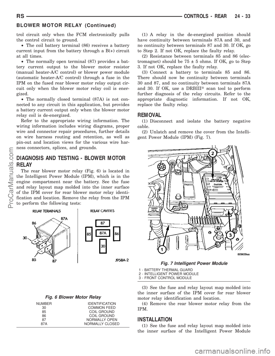
The rear blower motor relay (Fig. 6) is located in
the Intelligent Power Module (IPM), which is in the
engine compartment near the battery. See the fuse
and relay layout map molded into the inner surface
of the IPM cover for rear blower motor relay identi-
fication and location. Remove the relay from the IPM
to perform the following tests:(1) A relay in the de-energized position should
have continuity between terminals 87A and 30, and
no continuity between terminals 87 and 30. If OK, go
to Step 2. If not OK, replace the faulty relay.
(2) Resistance between terminals 85 and 86 (elec-
tromagnet) should be 75 5 ohms. If OK, go to Step
3. If not OK, replace the faulty relay.
(3) Connect a battery to terminals 85 and 86.
There should now be continuity between terminals
30 and 87, and no continuity between terminals 87A
and 30. If OK, use a DRBIIItscan tool to perform
further diagnosis of the relay circuits. Refer to the
appropriate diagnostic information. If not OK,
replace the faulty relay.
REMOVAL
(1) Disconnect and isolate the battery negative
cable.
(2) Unlatch and remove the cover from the Intelli-
gent Power Module (IPM) (Fig. 7).
(3) See the fuse and relay layout map molded into
the inner surface of the IPM cover for rear blower
motor relay identification and location.
(4) Remove the rear blower motor relay from the
IPM.
INSTALLATION
(1) See the fuse and relay layout map molded into
the inner surface of the Intelligent Power Module
Fig. 6 Blower Motor Relay
NUMBER IDENTIFICATION
30 COMMON FEED
85 COIL GROUND
86 COIL GROUND
87 NORMALLY OPEN
87A NORMALLY CLOSED
Fig. 7 Intelligent Power Module
1 - BATTERY THERMAL GUARD
2 - INTELLIGENT POWER MODULE
3 - FRONT CONTROL MODULE
RSCONTROLS - REAR24-33
BLOWER MOTOR RELAY (Continued)
ProCarManuals.com
Page 2172 of 2177

TEMPERATURE SENSOR - 3.3/3.8L -
INSTALLATION, ENGINE COOLANT........7-22
TEMPERATURE SENSOR - 3.3/3.8L -
REMOVAL, ENGINE COOLANT............7-21
TEMPERATURE SENSOR - DESCRIPTION,
BATTERY...........................8F-23
TEMPERATURE SENSOR - DESCRIPTION,
EVAPORATOR.......................24-22
TEMPERATURE SENSOR - DESCRIPTION,
INFRARED.....................24-23,24-35
TEMPERATURE SENSOR - DESCRIPTION,
INLET AIR..........................14-29
TEMPERATURE SENSOR - DIAGNOSIS
AND TESTING, AMBIENT..............8M-12
TEMPERATURE SENSOR -
INSTALLATION, EVAPORATOR...........24-23
TEMPERATURE SENSOR - OPERATION,
BATTERY...........................8F-23
TEMPERATURE SENSOR - OPERATION,
EVAPORATOR.......................24-23
TEMPERATURE SENSOR - OPERATION,
INFRARED.....................24-24,24-35
TEMPERATURE SENSOR - OPERATION,
INLET AIR..........................14-29
TEMPERATURE SENSOR - REMOVAL,
BATTERY...........................8F-23
TEMPERATURE SENSOR - REMOVAL,
EVAPORATOR.......................24-23
TEMPERATURE SENSOR -
SPECIFICATIONS, BATTERY.............8F-22
TEMPERATURE SENSOR CIRCUIT -
DIAGNOSIS AND TESTING, AMBIENT....8M-12
TENSION - STANDARD PROCEDURE,
CHECKING POWER STEERING BELT.........7-8
TENSION RELEASE - STANDARD
PROCEDURE, PARKING BRAKE
AUTOMATIC ADJUSTER................5-58
TENSION RESET - STANDARD
PROCEDURE, PARKING BRAKE
AUTOMATIC ADJUSTER................5-59
TENSION, SPECIFICATIONS -
ACCESSORY DRIVE BELT................7-5
TENSIONER - 2.4L - INSTALLATION,
BELT ...............................7-10
TENSIONER - 2.4L - REMOVAL, BELT......7-10
TENSIONER - 3.3/3.8L - INSTALLATION,
BELT ...............................7-12
TENSIONER - 3.3/3.8L - REMOVAL, BELT . . . 7-12
TENSIONER - DESCRIPTION, SEAT BELT . . 8O-16
TENSIONER - OPERATION, SEAT BELT....8O-16
TENSIONER & PULLEY - INSTALLATION,
TIMING BELT.........................9-69
TENSIONER & PULLEY - REMOVAL,
TIMING BELT.........................9-68
TERMINAL - INSTALLATION.........8W-01-14
TERMINAL - REMOVAL.............8W-01-14
TERMINAL REPAIR - STANDARD
PROCEDURE, GRID LINE...............8G-3
TEST - DIAGNOSIS AND TESTING, A/C
COOL DOWN.........................24-4
TEST - DIAGNOSIS AND TESTING, A/C
PERFORMANCE.......................24-5
TEST - DIAGNOSIS AND TESTING,
CONTROL CIRCUIT...................8F-30
TEST - DIAGNOSIS AND TESTING,
COOLING SYSTEM LEAK.................7-2
TEST - DIAGNOSIS AND TESTING,
CYLINDER COMBUSTION PRESSURE
LEAKAGE.........................9-83,9-9
TEST - DIAGNOSIS AND TESTING,
CYLINDER COMPRESSION PRESSURE . . 9-83,9-9
TEST - DIAGNOSIS AND TESTING, FEED
CIRCUIT............................8F-33
TEST - DIAGNOSIS AND TESTING, FEED
CIRCUIT RESISTANCE.................8F-32
TEST - DIAGNOSIS AND TESTING,
HEATED MIRROR.....................8G-5
TEST - DIAGNOSIS AND TESTING,
HEATER PERFORMANCE................24-6
TEST - DIAGNOSIS AND TESTING,
POWER STEERING SYSTEM FLOW
AND PRESSURE
......................19-1
TEST - DIAGNOSIS AND TESTING, ROAD
. . . 8P-3
TEST - DIAGNOSIS AND TESTING, ROAD
. 21-119
TEST - DIAGNOSIS AND TESTING,
STARTING SYSTEM
...................8F-28
TEST - DIAGNOSIS AND TESTING,
SYSTEM
............................8G-3TEST - STANDARD PROCEDURE,
IGNITION-OFF DRAW..................8F-13
TEST - STANDARD PROCEDURE,
OPEN-CIRCUIT VOLTAGE...............8F-13
TEST MODE, OPERATION - DRB IIIT
STATE DISPLAY.......................25-9
TESTS - DIAGNOSIS AND TESTING,
CLUTCH AIR PRESSURE..............21-122
TESTS - DIAGNOSIS AND TESTING,
HYDRAULIC PRESSURE..............21-120
THEFT SECURITY - DESCRIPTION,
VEHICLE............................8Q-1
THEFT SECURITY - OPERATION, VEHICLE . . 8Q-1
THEFT SECURITY SYSTEM - DIAGNOSIS
AND TESTING, VEHICLE................8Q-3
THERMOSTAT - 2.4L - INSTALLATION,
ENGINE COOLANT.....................7-23
THERMOSTAT - 2.4L - REMOVAL,
ENGINE COOLANT.....................7-23
THERMOSTAT - 3.3/3.8L -
INSTALLATION, ENGINE COOLANT........7-24
THERMOSTAT - 3.3/3.8L - REMOVAL,
ENGINE COOLANT.....................7-23
THERMOSTAT - DESCRIPTION, ENGINE
COOLANT............................7-22
THERMOSTAT - DIAGNOSIS AND
TESTING, ENGINE COOLANT.............7-23
THERMOSTAT - OPERATION, ENGINE
COOLANT............................7-22
THERMOWRAP - DESCRIPTION.........8F-19
THERMOWRAP - INSTALLATION.........8F-19
THERMOWRAP - OPERATION...........8F-19
THERMOWRAP - REMOVAL............8F-19
THIRD ROW - INSTALLATION, BENCH
SEAT RISER........................23-100
THIRD ROW - REMOVAL, BENCH SEAT
RISER............................23-100
THREAD REPAIR - DESCRIPTION, FRONT
CRADLE CROSSMEMBER...............13-9
THREAD REPAIR - STANDARD
PROCEDURE, MANIFOLD STRIPPED......9-145
THREADED HOLE REPAIR -
DESCRIPTION......................Intro.-5
THREADS - STANDARD PROCEDURE,
REPAIR OF DAMAGED OR WORN.....9-10,9-86
THREE PASSENGER BENCH -
INSTALLATION, SEAT BELT BUCKLE -
SECOND ROW.......................8O-14
THREE PASSENGER BENCH - REMOVAL,
SEAT BELT BUCKLE - SECOND ROW.....8O-14
THREE ZONE - DESCRIPTION, MANUAL....24-1
THREE ZONE - OPERATION, MANUAL.....24-3
THREE ZONE ATC - OPERATION..........24-3
THROTTLE BODY - DESCRIPTION........14-34
THROTTLE BODY - INSTALLATION.......14-35
THROTTLE BODY - OPERATION.........14-34
THROTTLE BODY - REMOVAL...........14-35
THROTTLE CONTROL CABLE -
INSTALLATION.......................14-35
THROTTLE CONTROL CABLE - REMOVAL . . 14-35
THROTTLE POSITION SENSOR -
DESCRIPTION.......................14-36
THROTTLE POSITION SENSOR -
OPERATION.........................14-36
TIE ROD - INSTALLATION, OUTER.......19-34
TIE ROD - REMOVAL, OUTER...........19-34
TIMING BELT - INSTALLATION...........9-65
TIMING BELT - REMOVAL
...............9-63
TIMING BELT COVER(S) - INSTALLATION
. . . 9-62
TIMING BELT COVER(S) - REMOVAL
......9-61
TIMING BELT TENSIONER & PULLEY -
INSTALLATION
........................9-69
TIMING BELT TENSIONER & PULLEY -
REMOVAL
...........................9-68
TIMING CHAIN AND CAMSHAFT
SPROCKET - INSTALLATION
............9-157
TIMING CHAIN AND CAMSHAFT
SPROCKET - REMOVAL
................9-156
TIMING CHAIN COVER - INSTALLATION
. . . 9-155
TIMING CHAIN COVER - REMOVAL
......9-153
TIMING CHAIN WEAR - STANDARD
PROCEDURE, MEASURING
.............9-153
TIMING VERIFICATION - STANDARD
PROCEDURE, VALVE
..................9-153
TIRE - DESCRIPTION
..................22-13
TIRE AND WHEEL ASSEMBLY
(ALUMINUM WHEEL) - INSTALLATION
.....22-8TIRE AND WHEEL ASSEMBLY
(ALUMINUM WHEEL) - REMOVAL........22-7
TIRE AND WHEEL ASSEMBLY (STEEL
WHEEL) - INSTALLATION...............22-8
TIRE AND WHEEL ASSEMBLY (STEEL
WHEEL) - REMOVAL...................22-8
TIRE AND WHEEL BALANCE -
STANDARD PROCEDURE................22-5
TIRE AND WHEEL MATCH MOUNTING -
STANDARD PROCEDURE................22-7
TIRE AND WHEEL ROTATION -
STANDARD PROCEDURE................22-7
TIRE AND WHEEL VIBRATION -
DIAGNOSIS AND TESTING..............22-1
TIRE INFLATION PRESSURES -
STANDARD PROCEDURE...............22-16
TIRE LEAK REPAIRING - STANDARD
PROCEDURE........................22-17
TIRE NOISE - DIAGNOSIS AND TESTING . . 22-14
TIRE PRESSURE FOR HIGH SPEED
OPERATION - STANDARD PROCEDURE . . . 22-17
TIRE PRESSURE MONITORING -
DESCRIPTION........................22-9
TIRE PRESSURE MONITORING -
OPERATION..........................22-9
TIRE PRESSURE SENSOR - DIAGNOSIS
AND TESTING.......................22-10
TIRE PRESSURE SENSOR RETRAIN -
STANDARD PROCEDURE...............22-10
TIRE (TEMPORARY) - DESCRIPTION,
SPARE .............................22-14
TIRE WEAR PATTERNS - DIAGNOSIS
AND TESTING.......................22-16
TIRES - CLEANING...................22-17
TIRES - DESCRIPTION, RADIAL-PLY......22-14
TIRES - DESCRIPTION, REPLACEMENT . . . 22-14
TIRE/VEHICLE LEAD - DIAGNOSIS AND
TESTING...........................22-14
TO CYLINDER BORE FITTING -
STANDARD PROCEDURE, PISTON........9-42
TO FILLER NECK SEAL - DIAGNOSIS
AND TESTING, RADIATOR CAP...........7-27
TO GROUND - STANDARD PROCEDURE,
TESTING FOR A SHORT.............8W-01-9
TO GROUND ON FUSES POWERING
SEVERAL LOADS - STANDARD
PROCEDURE, TESTING FOR A SHORT . 8W-01-10
TO USE WIRING DIAGRAMS -
DESCRIPTION, HOW................8W-01-1
TONE WHEEL - INSPECTION.............5-82
TONE WHEEL RUNOUT, SPECIFICATIONS . . . 5-79
TOOLS - 2.4L ENGINE, SPECIAL..........9-21
TOOLS - 3.3/3.8L ENGINE, SPECIAL.......9-95
TOOLS - 41TE AUTOMATIC TRANSAXLE,
SPECIAL..........................21-183
TOOLS - BASE BRAKE SYSTEM, SPECIAL . . 5-10
TOOLS - BATTERY SYSTEM SPECIAL
TOOLS, SPECIAL......................8F-7
TOOLS - BODY, SPECIAL...............23-13
TOOLS - COOLING SYSTEM, SPECIAL......7-6
TOOLS - EXHAUST SYSTEM, SPECIAL.....11-4
TOOLS - FRONT SUSPENSION, SPECIAL....2-3
TOOLS - FUEL, SPECIAL...........14-23,14-3
TOOLS - OVERHEAD CONSOLE, SPECIAL . . 8M-6
TOOLS - POWER DISTRIBUTION
SYSTEMS, SPECIAL................8W-97-2
TOOLS - POWER STEERING GEAR,
SPECIAL...........................19-34
TOOLS - POWER STEERING PUMP,
SPECIAL...........................19-43
TOOLS - POWER STEERING, SPECIAL.....19-9
TOOLS - REAR SUSPENSION, SPECIAL....2-28
TOOLS - SDP POWER TRANSFER UNIT,
SPECIAL............................21-8
TOOLS - WIRING/TERMINAL, SPECIAL . 8W-01-10
TOOLS, DIAGNOSIS AND TESTING -
SPECIAL............................3-34
TOOLS, SPECIAL TOOLS - BATTERY
SYSTEM SPECIAL.....................8F-7
TOOLS, SPECIFICATIONS - SPECIAL......8F-23
TOOLS, T850 TRANSAXLE - SPECIAL
.......6-6
TOOLS, T850 TRANSAXLE - SPECIAL
.....21-58
TOP COVER - INSTALLATION,
INSTRUMENT PANEL
..................23-67
TOP COVER - REMOVAL, INSTRUMENT
PANEL
.............................23-67
TOP PAD ASSEMBLY - INSTALLATION,
INSTRUMENT PANEL
..................23-70
RSINDEX33
Description Group-Page Description Group-Page Description Group-Page
ProCarManuals.com