ECU CHRYSLER CARAVAN 2003 Service Manual
[x] Cancel search | Manufacturer: CHRYSLER, Model Year: 2003, Model line: CARAVAN, Model: CHRYSLER CARAVAN 2003Pages: 2177, PDF Size: 59.81 MB
Page 1 of 2177
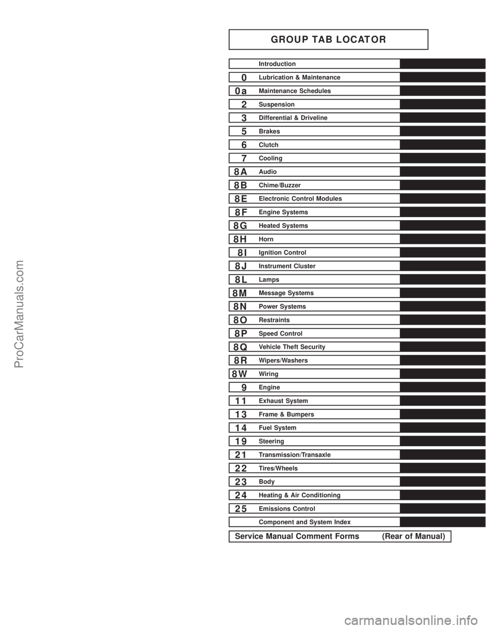
GROUP TAB LOCATOR
Introduction
0Lubrication & Maintenance
0aMaintenance Schedules
2Suspension
3Differential & Driveline
5Brakes
6Clutch
7Cooling
8AAudio
8BChime/Buzzer
8EElectronic Control Modules
8FEngine Systems
8GHeated Systems
8HHorn
8IIgnition Control
8JInstrument Cluster
8LLamps
8MMessage Systems
8NPower Systems
8ORestraints
8PSpeed Control
8QVehicle Theft Security
8RWipers/Washers
8WWiring
9Engine
11Exhaust System
13Frame & Bumpers
14Fuel System
19Steering
21Transmission/Transaxle
22Tires/Wheels
23Body
24Heating & Air Conditioning
25Emissions Control
Component and System Index
Service Manual Comment Forms (Rear of Manual)
ProCarManuals.com
Page 28 of 2177
* This maintenance is recommended by the manu-
facture to the owner but is not required to maintain
the emissions warranty.
³ This maintenance is not required if previously
replaced.
Inspection and service should also be performed
anytime a malfunction is observed or suspected.
Retain all receipts.
WARNING: You can be badly injured working on or
around a motor vehicle. Do only that service work
for which you have the knowledge and the right
equipment. If you have any doubt about your ability
to perform a service job, take your vehicle to a
competent mechanic.
HOISTING
STANDARD PROCEDURE - HOISTING
Refer to Owner's Manual provided with vehicle for
proper emergency jacking procedures.
WARNING: THE HOISTING AND JACK LIFTING
POINTS PROVIDED ARE FOR A COMPLETE VEHI-
CLE. WHEN THE ENGINE OR REAR SUSPENSION
IS REMOVED FROM A VEHICLE, THE CENTER OF
GRAVITY IS ALTERED MAKING SOME HOISTING
CONDITIONS UNSTABLE. PROPERLY SUPPORT OR
SECURE VEHICLE TO HOISTING DEVICE WHEN
THESE CONDITIONS EXIST.
CAUTION: Do not position hoisting device on any
suspension component, including the front suspen-
sion crossmember, the rear leaf springs, and the
rear axle. Do not hoist on the front and rear
bumpers, the lower liftgate crossmember, the lower
radiator crossmember, the down standing flanges
on the sill or the front engine mount.
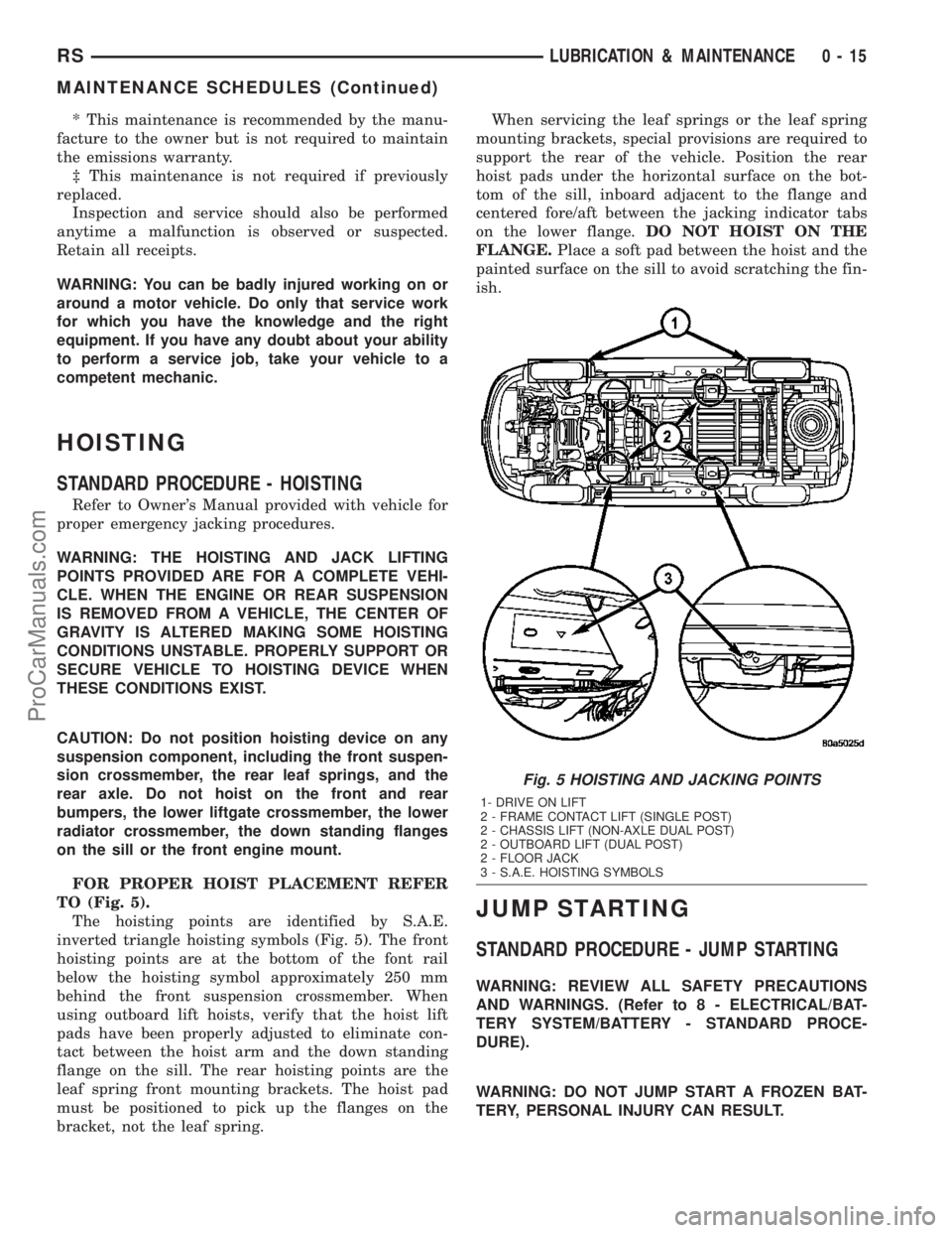
FOR PROPER HOIST PLACEMENT REFER
TO (Fig. 5).
The hoisting points are identified by S.A.E.
inverted triangle hoisting symbols (Fig. 5). The front
hoisting points are at the bottom of the font rail
below the hoisting symbol approximately 250 mm
behind the front suspension crossmember. When
using outboard lift hoists, verify that the hoist lift
pads have been properly adjusted to eliminate con-
tact between the hoist arm and the down standing
flange on the sill. The rear hoisting points are the
leaf spring front mounting brackets. The hoist pad
must be positioned to pick up the flanges on the
bracket, not the leaf spring.When servicing the leaf springs or the leaf spring
mounting brackets, special provisions are required to
support the rear of the vehicle. Position the rear
hoist pads under the horizontal surface on the bot-
tom of the sill, inboard adjacent to the flange and
centered fore/aft between the jacking indicator tabs
on the lower flange.DO NOT HOIST ON THE
FLANGE.Place a soft pad between the hoist and the
painted surface on the sill to avoid scratching the fin-
ish.
JUMP STARTING
STANDARD PROCEDURE - JUMP STARTING
WARNING: REVIEW ALL SAFETY PRECAUTIONS
AND WARNINGS. (Refer to 8 - ELECTRICAL/BAT-
TERY SYSTEM/BATTERY - STANDARD PROCE-
DURE).
WARNING: DO NOT JUMP START A FROZEN BAT-
TERY, PERSONAL INJURY CAN RESULT.
Fig. 5 HOISTING AND JACKING POINTS
1- DRIVE ON LIFT
2 - FRAME CONTACT LIFT (SINGLE POST)
2 - CHASSIS LIFT (NON-AXLE DUAL POST)
2 - OUTBOARD LIFT (DUAL POST)
2 - FLOOR JACK
3 - S.A.E. HOISTING SYMBOLS
RSLUBRICATION & MAINTENANCE0-15
MAINTENANCE SCHEDULES (Continued)
ProCarManuals.com
Page 30 of 2177
TOWING
STANDARD PROCEDURE - TOWING
WARNINGS AND CAUTIONS
WARNING: DO NOT ALLOW TOWING ATTACHMENT
DEVICES TO CONTACT THE FUEL TANK OR LINES,
FUEL LEAK CAN RESULT.
DO NOT LIFT OR TOW VEHICLE BY FRONT OR
REAR BUMPER.
DO NOT GO UNDER A LIFTED VEHICLE IF NOT
SUPPORTED PROPERLY ON SAFETY STANDS.
DO NOT ALLOW PASSENGERS TO RIDE IN A
TOWED VEHICLE.
USE A SAFETY CHAIN THAT IS INDEPENDENT
FROM THE TOWING ATTACHMENT DEVICE.
CAUTION: Do not damage brake lines, exhaust sys-
tem, shock absorbers, sway bars, or any other
under vehicle components when attaching towing
device to vehicle.
Do not secure vehicle to towing device by the use
of front or rear suspension or steering components.
Remove or secure loose or protruding objects from
a damaged vehicle before towing.
Refer to state and local rules and regulations before
towing a vehicle.
Do not allow weight of towed vehicle to bear on
lower fascia, air dams, or spoilers.
RECOMMENDED TOWING EQUIPMENT
To avoid damage to bumper fascia and air dams
use:
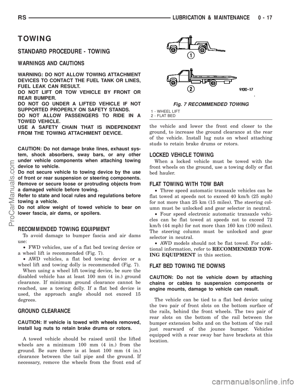
²FWD vehicles, use of a flat bed towing device or
a wheel lift is recommended (Fig. 7).
²AWD vehicles, a flat bed towing device or a
wheel lift and towing dolly is recommended (Fig. 7).
When using a wheel lift towing device, be sure the
disabled vehicle has at least 100 mm (4 in.) ground
clearance. If minimum ground clearance cannot be
reached, use a towing dolly. If a flat bed device is
used, the approach angle should not exceed 15
degrees.
GROUND CLEARANCE
CAUTION: If vehicle is towed with wheels removed,
install lug nuts to retain brake drums or rotors.
A towed vehicle should be raised until the lifted
wheels are a minimum 100 mm (4 in.) from the
ground. Be sure there is at least 100 mm (4 in.)
clearance between the tail pipe and the ground. If
necessary, remove the wheels from the front end ofthe vehicle and lower the front end closer to the
ground, to increase the ground clearance at the rear
of the vehicle. Install lug nuts on wheel attaching
studs to retain brake drums or rotors.
LOCKED VEHICLE TOWING
When a locked vehicle must be towed with the
front wheels on the ground, use a towing dolly or flat
bed hauler.
FLAT TOWING WITH TOW BAR
²Three speed automatic transaxle vehicles can be
flat towed at speeds not to exceed 40 km/h (25 mph)
for not more than 25 km (15 miles). The steering col-
umn must be unlocked and gear selector in neutral.
²Four speed electronic automatic transaxle vehi-
cles can be flat towed at speeds not to exceed 72
km/h (44 mph) for not more than 160 km (100 miles).
The steering column must be unlocked and gear
selector in neutral.
²AWD models should not be flat towed. For addi-
tional information, refer toRECOMMENDED TOW-
ING EQUIPMENTin this section.
FLAT BED TOWING TIE DOWNS
CAUTION: Do not tie vehicle down by attaching
chains or cables to suspension components or
engine mounts, damage to vehicle can result.
The vehicle can be tied to a flat bed device using
the two pair of front slots on the bottom surface of
the rails, behind the front wheels. The two pair of
rear slots on the bottom of the rail between the
bumper extension bolts and on the bottom of the rail
just rearward of the jounce bumper. Vehicles
equipped with a rear sway bar have brackets at this
location.
Fig. 7 RECOMMENDED TOWING
1 - WHEEL LIFT
2 - FLAT BED
RSLUBRICATION & MAINTENANCE0-17
ProCarManuals.com
Page 31 of 2177
TOWING ± FRONT WHEEL LIFT
If the vehicle is being towed from the front, when-
ever possible ensure at least 10 inches road clearance
to the tires.
TOWING ± REAR WHEEL LIFT
If a vehicle cannot be towed with the front wheels
lifted, the rear wheels can be lifted provided the fol-
lowing guide lines are observed.
CAUTION: Do not use steering column lock to
secure steering wheel during towing operation.
²On AWD vehicles, all four wheels must be free to
rotate. Use towing dollies at unlifted end of vehicle.²Unlock steering column and secure steering
wheel in straight ahead position with a clamp device
designed for towing.
²Three speed automatic transaxle vehicles can be
flat towed at speeds not to exceed 40 km/h (25 mph)
for not more than 25 km (15 miles). The steering col-
umn must be unlocked and gear selector in neutral.
²Four speed electronic automatic transaxle vehi-
cles can be flat towed at speeds not to exceed 72
km/h (44 mph) for not more than 160 km (100 miles).
The steering column must be unlocked and gear
selector in neutral.
0 - 18 LUBRICATION & MAINTENANCERS
TOWING (Continued)
ProCarManuals.com
Page 47 of 2177
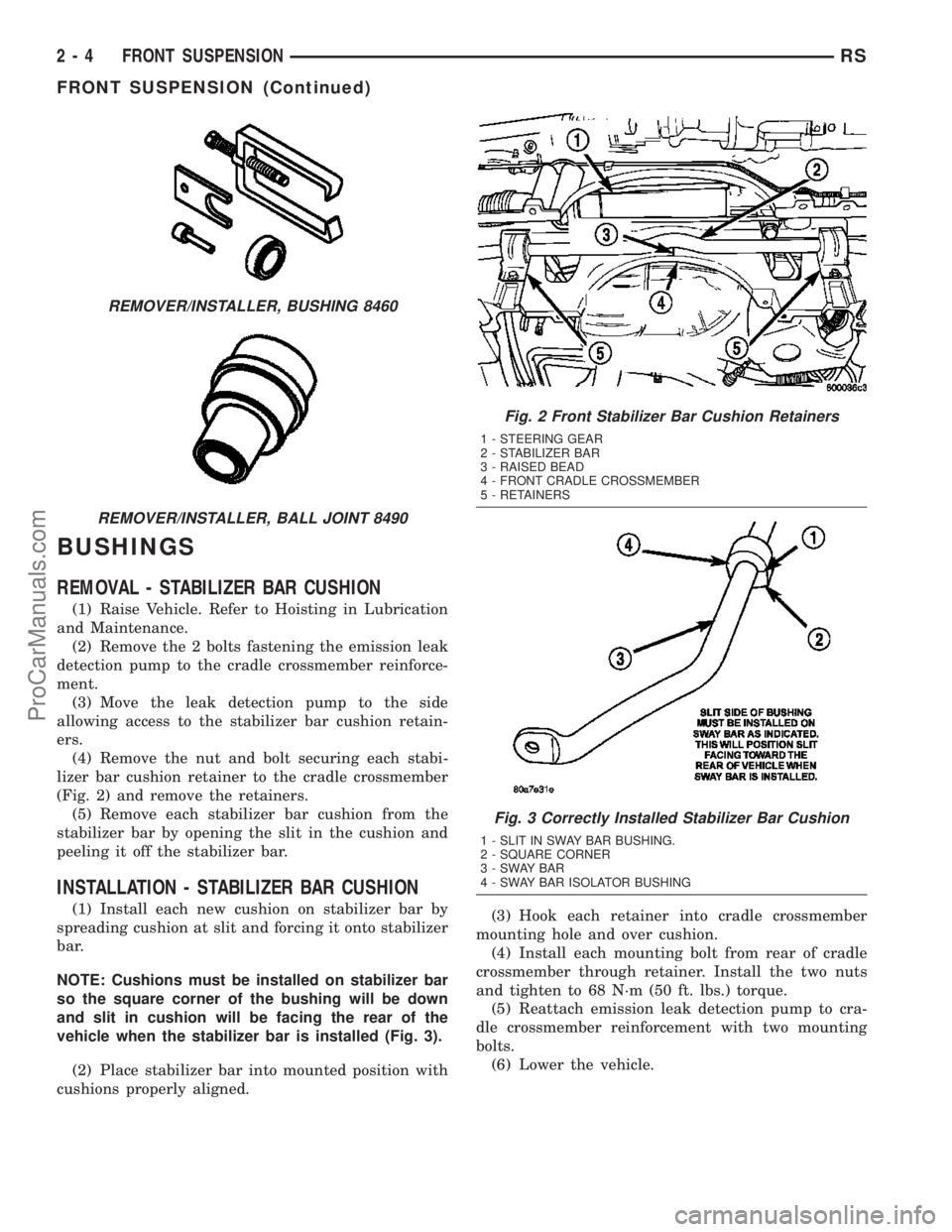
BUSHINGS
REMOVAL - STABILIZER BAR CUSHION
(1) Raise Vehicle. Refer to Hoisting in Lubrication
and Maintenance.
(2) Remove the 2 bolts fastening the emission leak
detection pump to the cradle crossmember reinforce-
ment.
(3) Move the leak detection pump to the side
allowing access to the stabilizer bar cushion retain-
ers.
(4) Remove the nut and bolt securing each stabi-
lizer bar cushion retainer to the cradle crossmember
(Fig. 2) and remove the retainers.
(5) Remove each stabilizer bar cushion from the
stabilizer bar by opening the slit in the cushion and
peeling it off the stabilizer bar.
INSTALLATION - STABILIZER BAR CUSHION
(1) Install each new cushion on stabilizer bar by
spreading cushion at slit and forcing it onto stabilizer
bar.
NOTE: Cushions must be installed on stabilizer bar
so the square corner of the bushing will be down
and slit in cushion will be facing the rear of the
vehicle when the stabilizer bar is installed (Fig. 3).
(2) Place stabilizer bar into mounted position with
cushions properly aligned.(3) Hook each retainer into cradle crossmember
mounting hole and over cushion.
(4) Install each mounting bolt from rear of cradle
crossmember through retainer. Install the two nuts
and tighten to 68 N´m (50 ft. lbs.) torque.
(5) Reattach emission leak detection pump to cra-
dle crossmember reinforcement with two mounting
bolts.
(6) Lower the vehicle.
REMOVER/INSTALLER, BUSHING 8460
REMOVER/INSTALLER, BALL JOINT 8490
Fig. 2 Front Stabilizer Bar Cushion Retainers
1 - STEERING GEAR
2 - STABILIZER BAR
3 - RAISED BEAD
4 - FRONT CRADLE CROSSMEMBER
5 - RETAINERS
Fig. 3 Correctly Installed Stabilizer Bar Cushion
1 - SLIT IN SWAY BAR BUSHING.
2 - SQUARE CORNER
3-SWAYBAR
4 - SWAY BAR ISOLATOR BUSHING
2 - 4 FRONT SUSPENSIONRS
FRONT SUSPENSION (Continued)
ProCarManuals.com
Page 57 of 2177
DISASSEMBLY - LOWER CONTROL ARM
(REAR BUSHING - HYDRO)
(1) Remove the lower control arm from the front
suspension cradle. (Refer to 2 - SUSPENSION/
FRONT/LOWER CONTROL ARM - REMOVAL)
(2) Mount the lower control arm in a visewithout
using excessive clamping force.
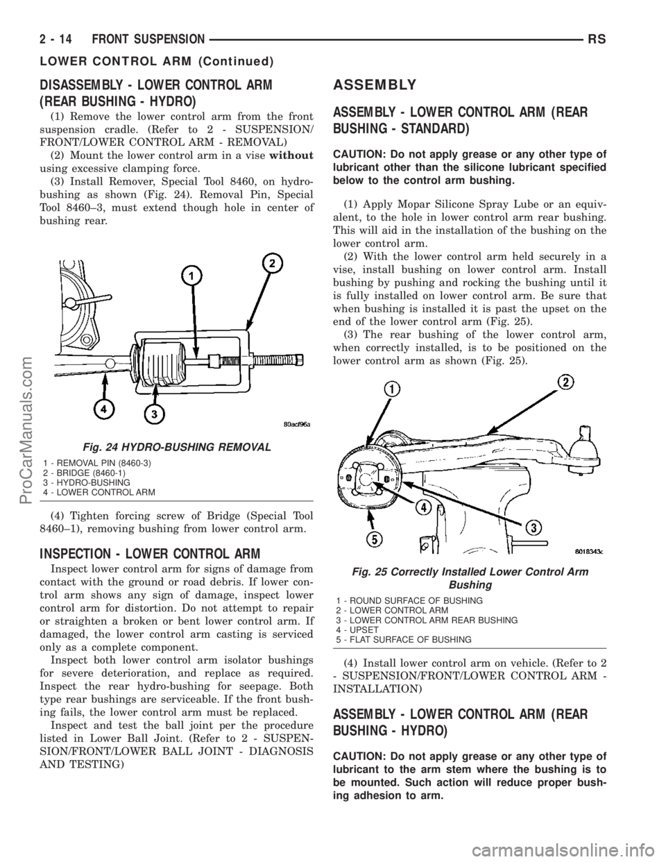
(3) Install Remover, Special Tool 8460, on hydro-
bushing as shown (Fig. 24). Removal Pin, Special
Tool 8460±3, must extend though hole in center of
bushing rear.
(4) Tighten forcing screw of Bridge (Special Tool
8460±1), removing bushing from lower control arm.
INSPECTION - LOWER CONTROL ARM
Inspect lower control arm for signs of damage from
contact with the ground or road debris. If lower con-
trol arm shows any sign of damage, inspect lower
control arm for distortion. Do not attempt to repair
or straighten a broken or bent lower control arm. If
damaged, the lower control arm casting is serviced
only as a complete component.
Inspect both lower control arm isolator bushings
for severe deterioration, and replace as required.
Inspect the rear hydro-bushing for seepage. Both
type rear bushings are serviceable. If the front bush-
ing fails, the lower control arm must be replaced.
Inspect and test the ball joint per the procedure
listed in Lower Ball Joint. (Refer to 2 - SUSPEN-
SION/FRONT/LOWER BALL JOINT - DIAGNOSIS
AND TESTING)
ASSEMBLY
ASSEMBLY - LOWER CONTROL ARM (REAR
BUSHING - STANDARD)
CAUTION: Do not apply grease or any other type of
lubricant other than the silicone lubricant specified
below to the control arm bushing.
(1) Apply Mopar Silicone Spray Lube or an equiv-
alent, to the hole in lower control arm rear bushing.
This will aid in the installation of the bushing on the
lower control arm.
(2) With the lower control arm held securely in a
vise, install bushing on lower control arm. Install
bushing by pushing and rocking the bushing until it
is fully installed on lower control arm. Be sure that
when bushing is installed it is past the upset on the
end of the lower control arm (Fig. 25).
(3) The rear bushing of the lower control arm,
when correctly installed, is to be positioned on the
lower control arm as shown (Fig. 25).
(4) Install lower control arm on vehicle. (Refer to 2
- SUSPENSION/FRONT/LOWER CONTROL ARM -
INSTALLATION)
ASSEMBLY - LOWER CONTROL ARM (REAR
BUSHING - HYDRO)
CAUTION: Do not apply grease or any other type of
lubricant to the arm stem where the bushing is to
be mounted. Such action will reduce proper bush-
ing adhesion to arm.
Fig. 24 HYDRO-BUSHING REMOVAL
1 - REMOVAL PIN (8460-3)
2 - BRIDGE (8460-1)
3 - HYDRO-BUSHING
4 - LOWER CONTROL ARM
Fig. 25 Correctly Installed Lower Control Arm
Bushing
1 - ROUND SURFACE OF BUSHING
2 - LOWER CONTROL ARM
3 - LOWER CONTROL ARM REAR BUSHING
4 - UPSET
5 - FLAT SURFACE OF BUSHING
2 - 14 FRONT SUSPENSIONRS
LOWER CONTROL ARM (Continued)
ProCarManuals.com
Page 58 of 2177
(1) Secure lower control arm in a vise.
NOTE: Hydro bushings and grooves on control arm
stems are unique for right and left sides. Left side
bushing master spline and control arm groove are
on the top (when mounted on vehicle). Right side
bushing master spline and control arm groove are
on the bottom (when mounted on vehicle).
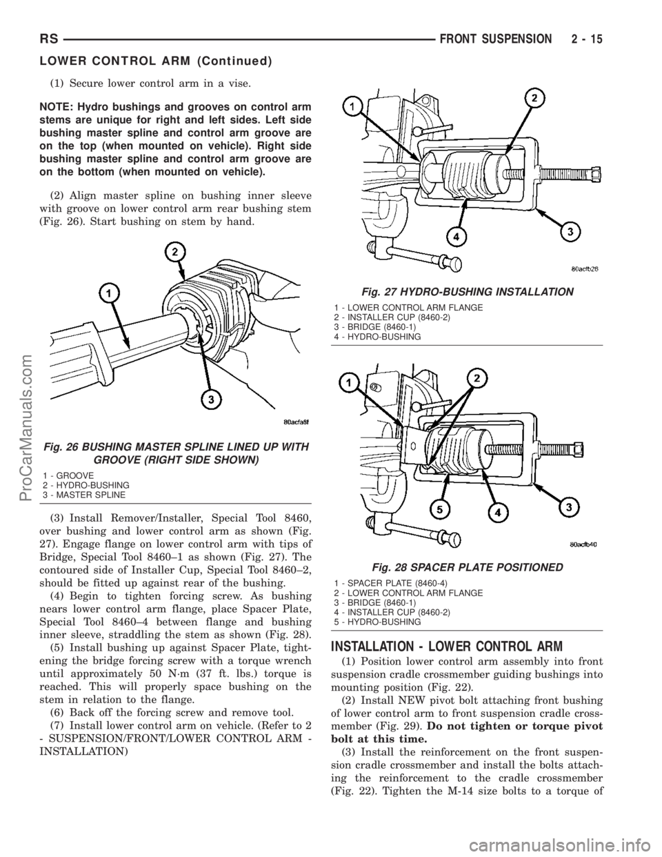
(2) Align master spline on bushing inner sleeve
with groove on lower control arm rear bushing stem
(Fig. 26). Start bushing on stem by hand.
(3) Install Remover/Installer, Special Tool 8460,
over bushing and lower control arm as shown (Fig.
27). Engage flange on lower control arm with tips of
Bridge, Special Tool 8460±1 as shown (Fig. 27). The
contoured side of Installer Cup, Special Tool 8460±2,
should be fitted up against rear of the bushing.
(4) Begin to tighten forcing screw. As bushing
nears lower control arm flange, place Spacer Plate,
Special Tool 8460±4 between flange and bushing
inner sleeve, straddling the stem as shown (Fig. 28).
(5) Install bushing up against Spacer Plate, tight-
ening the bridge forcing screw with a torque wrench
until approximately 50 N´m (37 ft. lbs.) torque is
reached. This will properly space bushing on the
stem in relation to the flange.
(6) Back off the forcing screw and remove tool.
(7) Install lower control arm on vehicle. (Refer to 2
- SUSPENSION/FRONT/LOWER CONTROL ARM -
INSTALLATION)
INSTALLATION - LOWER CONTROL ARM
(1) Position lower control arm assembly into front
suspension cradle crossmember guiding bushings into
mounting position (Fig. 22).
(2) Install NEW pivot bolt attaching front bushing
of lower control arm to front suspension cradle cross-
member (Fig. 29).Do not tighten or torque pivot
bolt at this time.
(3) Install the reinforcement on the front suspen-
sion cradle crossmember and install the bolts attach-
ing the reinforcement to the cradle crossmember
(Fig. 22). Tighten the M-14 size bolts to a torque of
Fig. 26 BUSHING MASTER SPLINE LINED UP WITH
GROOVE (RIGHT SIDE SHOWN)
1 - GROOVE
2 - HYDRO-BUSHING
3 - MASTER SPLINE
Fig. 27 HYDRO-BUSHING INSTALLATION
1 - LOWER CONTROL ARM FLANGE
2 - INSTALLER CUP (8460-2)
3 - BRIDGE (8460-1)
4 - HYDRO-BUSHING
Fig. 28 SPACER PLATE POSITIONED
1 - SPACER PLATE (8460-4)
2 - LOWER CONTROL ARM FLANGE
3 - BRIDGE (8460-1)
4 - INSTALLER CUP (8460-2)
5 - HYDRO-BUSHING
RSFRONT SUSPENSION2-15
LOWER CONTROL ARM (Continued)
ProCarManuals.com
Page 71 of 2177
DESCRIPTION N´mFt.
Lbs.In.
Lbs.
Leaf Spring Plate-To-Axle
Bolts95 70 Ð
Leaf Spring Rear Mount-To-
Body Bolts61 45 Ð
Leaf Spring Shackle Plate
Nuts61 45 Ð
Shock Absorber Mounting
Bolts88 65 Ð
Stabilizer Bar Bushing
Retainer Bolts61 45 Ð
Stabilizer Bar Link Nuts 61 45 Ð
Stabilizer Bar Link Frame
Bracket Mounting Bolts61 45 Ð
Track Bar Bracket-To-Body
Mount Bolts61 45 Ð
Track Bar Pivot Bolts 95 70 Ð
Wheel Mounting (Lug) Nut 135 100 Ð
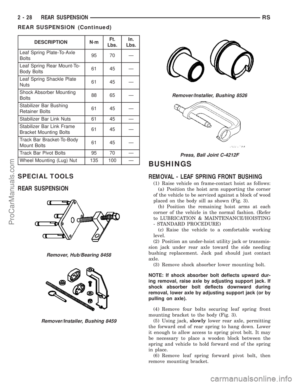
SPECIAL TOOLS
REAR SUSPENSION
BUSHINGS
REMOVAL - LEAF SPRING FRONT BUSHING
(1) Raise vehicle on frame-contact hoist as follows:
(a) Position the hoist arm supporting the corner
of the vehicle to be serviced against a block of wood
placed on the body sill as shown (Fig. 3).
(b) Position the remaining hoist arms at each
corner of the vehicle in the normal fashion. (Refer
to LUBRICATION & MAINTENANCE/HOISTING
- STANDARD PROCEDURE)
(c) Raise the vehicle to a comfortable working
level.
(2) Position an under-hoist utility jack or transmis-
sion jack under rear axle toward the side needing
bushing replacement. Jack pad should just contact
axle.
(3) Remove shock absorber lower mounting bolt.
NOTE: If shock absorber bolt deflects upward dur-
ing removal, raise axle by adjusting support jack. If
shock absorber bolt deflects downward during
removal, lower axle by adjusting support jack (or by
pulling on axle).
(4) Remove four bolts securing leaf spring front
mounting bracket to the body (Fig. 3).
(5) Using jack,slowlylower rear axle, permitting
the forward end of rear spring to hang down. Lower
it enough to allow access to spring pivot bolt. It may
be necessary to place a wooden block between the
spring and vehicle to hold forward end of the spring
in place.
(6) Remove leaf spring forward pivot bolt, then
remove mounting bracket.
Remover, Hub/Bearing 8458
Remover/Installer, Bushing 8459
Remover/Installer, Bushing 8526
Press, Ball Joint C-4212F
2 - 28 REAR SUSPENSIONRS
REAR SUSPENSION (Continued)
ProCarManuals.com
Page 72 of 2177
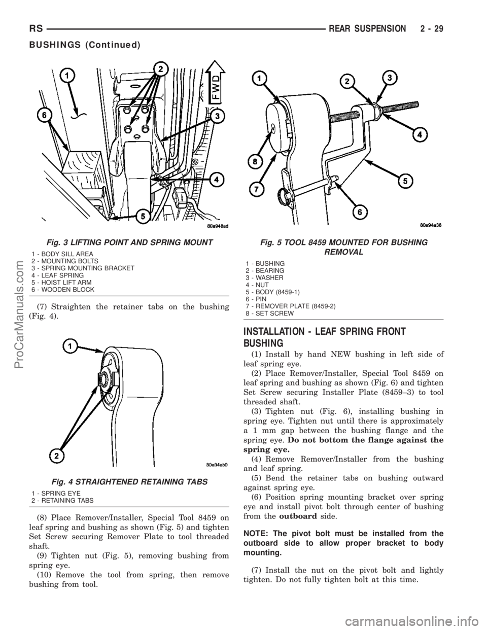
(7) Straighten the retainer tabs on the bushing
(Fig. 4).
(8) Place Remover/Installer, Special Tool 8459 on
leaf spring and bushing as shown (Fig. 5) and tighten
Set Screw securing Remover Plate to tool threaded
shaft.
(9) Tighten nut (Fig. 5), removing bushing from
spring eye.
(10) Remove the tool from spring, then remove
bushing from tool.
INSTALLATION - LEAF SPRING FRONT
BUSHING
(1) Install by hand NEW bushing in left side of
leaf spring eye.
(2) Place Remover/Installer, Special Tool 8459 on
leaf spring and bushing as shown (Fig. 6) and tighten
Set Screw securing Installer Plate (8459±3) to tool
threaded shaft.
(3) Tighten nut (Fig. 6), installing bushing in
spring eye. Tighten nut until there is approximately
a 1 mm gap between the bushing flange and the
spring eye.Do not bottom the flange against the
spring eye.
(4) Remove Remover/Installer from the bushing
and leaf spring.
(5) Bend the retainer tabs on bushing outward
against spring eye.
(6) Position spring mounting bracket over spring
eye and install pivot bolt through center of bushing
from theoutboardside.
NOTE: The pivot bolt must be installed from the
outboard side to allow proper bracket to body
mounting.
(7) Install the nut on the pivot bolt and lightly
tighten. Do not fully tighten bolt at this time.
Fig. 3 LIFTING POINT AND SPRING MOUNT
1 - BODY SILL AREA
2 - MOUNTING BOLTS
3 - SPRING MOUNTING BRACKET
4 - LEAF SPRING
5 - HOIST LIFT ARM
6 - WOODEN BLOCK
Fig. 4 STRAIGHTENED RETAINING TABS
1 - SPRING EYE
2 - RETAINING TABS
Fig. 5 TOOL 8459 MOUNTED FOR BUSHING
REMOVAL
1 - BUSHING
2 - BEARING
3 - WASHER
4 - NUT
5 - BODY (8459-1)
6 - PIN
7 - REMOVER PLATE (8459-2)
8 - SET SCREW
RSREAR SUSPENSION2-29
BUSHINGS (Continued)
ProCarManuals.com
Page 79 of 2177
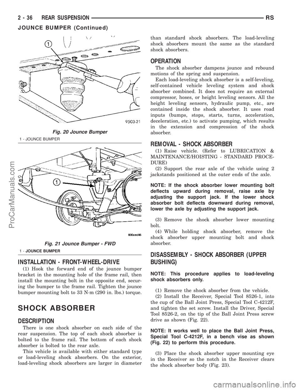
INSTALLATION - FRONT-WHEEL-DRIVE
(1) Hook the forward end of the jounce bumper
bracket in the mounting hole of the frame rail, then
install the mounting bolt in the opposite end, secur-
ing the bumper to the frame rail. Tighten the jounce
bumper mounting bolt to 33 N´m (290 in. lbs.) torque.
SHOCK ABSORBER
DESCRIPTION
There is one shock absorber on each side of the
rear suspension. The top of each shock absorber is
bolted to the frame rail. The bottom of each shock
absorber is bolted to the rear axle.
This vehicle is available with either standard type
or load-leveling shock absorbers. On the exterior,
load-leveling shock absorbers are larger in diameterthan standard shock absorbers. The load-leveling
shock absorbers mount the same as the standard
shock absorbers.
OPERATION
The shock absorber dampens jounce and rebound
motions of the spring and suspension.
Each load-leveling shock absorber is a self-leveling,
self-contained vehicle leveling system and shock
absorber combined. It does not require an external
compressor, hoses, or height leveling sensors. All the
height leveling sensors, hydraulic pump, etc., are
contained inside the shock absorber. It uses road
inputs (bumps, stops, starts, turns, acceleration,
deceleration, etc.) to activate pumping, which results
in the extension and compression of the shock
absorber.
REMOVAL - SHOCK ABSORBER
(1) Raise vehicle. (Refer to LUBRICATION &
MAINTENANCE/HOISTING - STANDARD PROCE-
DURE)
(2) Support the rear axle of the vehicle using 2
jackstands positioned at the outer ends of the axle.
NOTE: If the shock absorber lower mounting bolt
deflects upward during removal, raise axle by
adjusting the support jack. If the lower shock
absorber bolt deflects downward during removal,
lower the axle by adjusting the support jack.
(3) Remove the shock absorber lower mounting
bolt.
(4) While holding shock absorber, remove the
shock absorber upper mounting bolt and shock
absorber.
DISASSEMBLY - SHOCK ABSORBER (UPPER
BUSHING)
NOTE: This procedure applies to load-leveling
shock absorbers only.
(1) Remove the shock absorber from the vehicle.
(2) Install the Receiver, Special Tool 8526-1, into
the cup of the Ball Joint Press, Special Tool C-4212F,
and tighten the set screw. Install the Driver, Special
Tool 8526-2, on the tip of the Ball Joint Press screw
drive as shown (Fig. 22).
NOTE: It works well to place the Ball Joint Press,
Special Tool C-4212F, in a bench vise as shown
(Fig. 22) to perform this procedure.
(3) Place the shock absorber upper mounting eye
in the Receiver so the notch in the Receiver clears
the shock absorber body (Fig. 23).
Fig. 20 Jounce Bumper
1 - JOUNCE BUMPER
Fig. 21 Jounce Bumper - FWD
1-JOUNCE BUMPER
2 - 36 REAR SUSPENSIONRS
JOUNCE BUMPER (Continued)
ProCarManuals.com