ECO mode CHRYSLER CARAVAN 2003 Manual Online
[x] Cancel search | Manufacturer: CHRYSLER, Model Year: 2003, Model line: CARAVAN, Model: CHRYSLER CARAVAN 2003Pages: 2177, PDF Size: 59.81 MB
Page 2087 of 2177
REFRIGERANT OIL
DESCRIPTION
The refrigerant oil used in R-134a refrigerant sys-
tems is a synthetic-based, PolyAlkylene Glycol (PAG),
wax-free lubricant. Mineral-based R-12 refrigerant
oils are not compatible with PAG oils, and should
never be introduced to an R-134a refrigerant system.
There are different PAG oils available, and each con-
tains a different additive package. The 10S20H com-
pressor used in this vehicle are designed to use an
ND-8 PAG refrigerant oil. Use only refrigerant oil of
this same type to service the refrigerant system.
OPERATION
After performing any refrigerant recovery or recy-
cling operation, always replenish the refrigerant sys-
tem with the same amount of the recommended
refrigerant oil as was removed. Too little refrigerant
oil can cause compressor damage, and too much can
reduce air conditioning system performance. PAG
refrigerant oil is much more hygroscopic than min-
eral oil, and will absorb any moisture it comes into
contact with, even moisture in the air. The PAG oil
container should always be kept tightly capped until
it is ready to be used. After use, recap the oil con-
tainer immediately to prevent moisture contamina-
tion.
STANDARD PROCEDURE - REFRIGERANT OIL
LEVEL
WARNING: REFER TO THE APPLICABLE WARN-
INGS AND CAUTIONS FOR THIS SYSTEM BEFORE
PERFORMING THE FOLLOWING OPERATION.
(Refer to 24 - HEATING & AIR CONDITIONING/
PLUMBING - FRONT - WARNING - A/C PLUMBING)
and (Refer to 24 - HEATING & AIR CONDITIONING/
PLUMBING - FRONT - CAUTION - A/C PLUMBING).
When an air conditioning system is assembled at
the factory, all components except the compressor are
refrigerant oil free. After the refrigerant system has
been charged and operated, the refrigerant oil in the
compressor is dispersed throughout the refrigerant
system. The receiver/drier, evaporator, condenser, and
compressor will each retain a significant amount of
the needed refrigerant oil.
It is important to have the correct amount of oil in
the refrigerant system. This ensures proper lubrica-
tion of the compressor. Too little oil will result in
damage to the compressor. Too much oil will reduce
the cooling capacity of the air conditioning system.
It will not be necessary to check the oil level in the
compressor or to add oil, unless there has been an oil
loss. An oil loss may occur due to a rupture or leakfrom a refrigerant line, a connector fitting, a compo-
nent, or a component seal. If a leak occurs, add 30
milliliters (1 fluid ounce) of refrigerant oil to the
refrigerant system after the repair has been made.
Refrigerant oil loss will be evident at the leak point
by the presence of a wet, shiny surface around the
leak.
Refrigerant oil must be added when an receiver/
drier, evaporator or condenser is replaced. See the
Refrigerant Oil Capacities chart for the proper
amount of refrigerant oil to add. When a compressor
is replaced, the refrigerant oil must be drained from
the old compressor and measured. Drain all of the
refrigerant oil from the new compressor, then fill the
new compressor with the same amount of fresh new
refrigerant oil that was drained out of the old com-
pressor.
REFRIGERANT OIL CAPACITIES
Front A/C Front & Rear
A/C
COMPONENT ml fl oz ml fl oz
Total System Fill 140 5.0 180 6.43
Filter-Drier 25 0.9 25 0.9
Condenser 25 0.9 25 0.9
Front Evaporator 50 1.8 50 1.8
Rear Evap. (including
underbody lines)N/A N/A 50 1.8
Compressor Drain and measure the oil
from the old compressor -
See text above.
SUCTION LINE
REMOVAL
The front air conditioner suction line includes the
low side service port on a section of tubing located
near the compressor. On models equipped with the
optional rear air conditioner, the front air conditioner
suction line also includes a suction line hose and
tube extension that connects the front suction line to
the suction line for the rear air conditioner.
WARNING: REFER TO THE APPLICABLE WARN-
INGS AND CAUTIONS FOR THIS SYSTEM BEFORE
PERFORMING THE FOLLOWING OPERATION.
(Refer to 24 - HEATING & AIR CONDITIONING/
PLUMBING - FRONT - WARNING - A/C PLUMBING)
and (Refer to 24 - HEATING & AIR CONDITIONING/
PLUMBING - FRONT - CAUTION - A/C PLUMBING).
(1) Recover the refrigerant from the refrigerant
system. (Refer to 24 - HEATING & AIR CONDI-
24 - 90 PLUMBING - FRONTRS
ProCarManuals.com
Page 2088 of 2177
TIONING/PLUMBING - FRONT/REFRIGERANT -
STANDARD PROCEDURE - REFRIGERANT
RECOVERY).
(2) Disconnect and isolate the battery negative
cable.
(3) Remove the air cleaner top cover and snorkel
from the air cleaner housing located on the right side
of the engine compartment.
(4) Disconnect the drain tube from the wiper mod-
ule drain on the right side of the engine compart-
ment.
(5) Remove the nut that secures the suction line
fitting to the top of the compressor.
(6) Disconnect the suction line fitting from the
compressor suction port.
(7) Remove the seal from the suction line fitting
and discard.
(8) Install plugs in, or tape over the opened suc-
tion line fitting and the compressor suction port.
(9) Disengage the retainer that secures the suction
line routing clip to the filter-drier mounting bracket
on the side of the right front strut tower in the
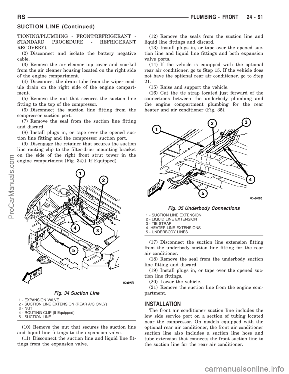
engine compartment (Fig. 34).( If Equipped).
(10) Remove the nut that secures the suction line
and liquid line fittings to the expansion valve.
(11) Disconnect the suction line and liquid line fit-
tings from the expansion valve.(12) Remove the seals from the suction line and
liquid line fittings and discard.
(13) Install plugs in, or tape over the opened suc-
tion line and liquid line fittings and both expansion
valve ports.
(14) If the vehicle is equipped with the optional
rear air conditioner, go to Step 15. If the vehicle does
not have the optional rear air conditioner, go to Step
21.
(15) Raise and support the vehicle.
(16) Cut the tie strap located just forward of the
connections between the underbody plumbing and
the engine compartment plumbing for the rear
heater and air conditioner (Fig. 35).
(17) Disconnect the suction line extension fitting
from the underbody suction line fitting for the rear
air conditioner.
(18) Remove the seal from the underbody suction
line fitting and discard.
(19) Install plugs in, or tape over the opened suc-
tion line fittings.
(20) Lower the vehicle.
(21) Remove the suction line from the engine com-
partment.
INSTALLATION
The front air conditioner suction line includes the
low side service port on a section of tubing located
near the compressor. On models equipped with the
optional rear air conditioner, the front air conditioner
suction line also includes a suction line hose and
tube extension that connects the front suction line to
the suction line for the rear air conditioner.
Fig. 34 Suction Line
1 - EXPANSION VALVE
2 - SUCTION LINE EXTENSION (REAR A/C ONLY)
3 - NUT
4 - ROUTING CLIP (If Equipped)
5 - SUCTION LINE
Fig. 35 Underbody Connections
1 - SUCTION LINE EXTENSION
2 - LIQUID LINE EXTENSION
3 - TIE STRAP
4- HEATER LINE EXTENSIONS
5 - UNDERBODY LINES
RSPLUMBING - FRONT24-91
SUCTION LINE (Continued)
ProCarManuals.com
Page 2094 of 2177
OPERATION
A mechanical sensor in the expansion valve control
head monitors the temperature and pressure of the
refrigerant leaving the evaporator coil through the
suction line, and adjusts the orifice size at the liquid
line to let the proper amount of refrigerant into the
evaporator coil to meet the vehicle cooling require-
ments. Controlling the refrigerant flow through the
evaporator ensures that none of the refrigerant leav-
ing the evaporator is still in a liquid state, which
could damage the compressor.
DIAGNOSIS AND TESTING - EXPANSION VALVE
WARNING: REFER TO THE APPLICABLE WARN-
INGS AND CAUTIONS FOR THIS SYSTEM BEFORE
PERFORMING THE FOLLOWING OPERATION.
(Refer to 24 - HEATING & AIR CONDITIONING/
PLUMBING - FRONT - WARNING - A/C PLUMBING)
and (Refer to 24 - HEATING & AIR CONDITIONING/
PLUMBING - FRONT - CAUTION - A/C PLUMBING).
NOTE: The expansion valve should only be tested
following testing of the compressor.
NOTE: Liquid CO
2is required to test the expansion
valve. This material is available from most welding
supply facilities. Liquid CO
2is also available from
companies which service and sell fire extinguish-
ers.
When testing the expansion valve, the work area
and the vehicle temperature must be 21É to 27É C
(70É to 85É F). To test the expansion valve:
(1) Connect a charging station or manifold gauge
set to the refrigerant system service ports. Verify the
refrigerant charge level.
(2) Close all doors, windows and vents to the pas-
senger compartment.
(3) Set the heater-air conditioner controls so that
the compressor is operating, the temperature control
is in the highest temperature position, the mode door
is directing the output to the floor outlets, and the
blower is operating at the highest speed setting.
(4) Start the engine and allow it to idle at 1000
rpm. After the engine has reached normal operating
temperature, allow the passenger compartment to
heat up. This will create the need for maximum
refrigerant flow into the evaporator.
(5) If the refrigerant charge is sufficient, the dis-
charge (high pressure) gauge should read 965 to 1655
kPa (140 to 240 psi). The suction (low pressure)
gauge should read 140 kPa to 207 kPa (20 psi to 30
psi). If OK, go to Step 6. If not OK, replace the faulty
expansion valve.WARNING: PROTECT THE SKIN AND EYES FROM
EXPOSURE TO LIQUID CO
2. PERSONAL INJURY
CAN RESULT.
(6) If the suction (low pressure) gauge reads
within the specified range, freeze the expansion valve
control head for 30 seconds using liquid CO
2or
another suitable super-cold material.Do not spray
R-134a or R-12 refrigerant on the expansion
valve control head for this test.The suction (low
pressure) gauge reading should drop by 10 psi. If OK,
go to Step 7 If not OK, replace the faulty expansion
valve.
(7) Allow the expansion valve control head to thaw.
The suction (low pressure) gauge reading should sta-
bilize at 140 kPa to 240 kPa (20 psi to 30 psi). If not
OK, replace the faulty expansion valve.
(8) When expansion valve testing is complete, test
the overall air conditioner performance. (Refer to 24 -
HEATING & AIR CONDITIONING - DIAGNOSIS
AND TESTING - A/C PERFORMANCE TEST).
Remove all test equipment before returning the vehi-
cle to service.
REMOVAL
WARNING: REFER TO THE APPLICABLE WARN-
INGS AND CAUTIONS FOR THIS SYSTEM BEFORE
PERFORMING THE FOLLOWING OPERATION.
(Refer to 24 - HEATING & AIR CONDITIONING/
PLUMBING - FRONT - WARNING - A/C PLUMBING),
(Refer to 24 - HEATING & AIR CONDITIONING/
PLUMBING - FRONT - CAUTION - A/C PLUMBING),
and (Refer to 24 - HEATING & AIR CONDITIONING/
PLUMBING - FRONT - WARNING - HEATER PLUMB-
ING).
(1) Remove the rear heater-A/C unit housing from
the vehicle. (Refer to 24 - HEATING & AIR CONDI-
TIONING/DISTRIBUTION - REAR/REAR HEATER-
A/C HOUSING - REMOVAL).
(2) Carefully remove the foam insulator wrap from
the rear expansion valve.
(3) Remove the rear evaporator line extension from
the expansion valve. (Refer to 24 - HEATING & AIR
CONDITIONING/PLUMBING - REAR/EVAPORA-
TOR - REMOVAL - EVAPORATOR LINE EXTEN-
SION).
(4) Remove the two screws that secure the expan-
sion valve to the evaporator tube sealing plate.
(5) Remove the expansion valve from the evapora-
tor tubes.
(6) Remove the seals from the evaporator tube fit-
tings and discard.
(7) Install plugs in, or tape over the opened evap-
orator tube fittings and both expansion valve ports.
RSPLUMBING - REAR24-97
EXPANSION VALVE (Continued)
ProCarManuals.com
Page 2098 of 2177
(4) Compress insert in rear heater hose quick con-
nection and pull downward on hose.
(5) Remove (3) straps securing underbody lines.
(6) Separate and remove rear heater lines from
vehicle.
INSTALLATION
There are several heater core plumbing configura-
tions used on this model, depending upon the engine
size and other optional equipment. One plumbing
configuration is used for all 2.4L engines, while the
3.3L and 3.8L engines have unique heater return
plumbing on the engine for models with or without
an optional engine oil cooler. There are also unique
plumbing configurations at the heater core for mod-
els with or without the optional rear heater and air
conditioner. All models use a combination of formed
steel tubing and rubber hoses. In most cases, the
rubber hose is secured to the steel tubing with a
spring tension clamp.
WARNING: REFER TO THE APPLICABLE WARN-
INGS AND CAUTIONS FOR THIS SYSTEM BEFORE
PERFORMING THE FOLLOWING OPERATION.
(Refer to 24 - HEATING & AIR CONDITIONING/
PLUMBING FRONT - WARNING - HEATER PLUMB-
ING).
(1) Using spring tension clamp pliers, compress
and slide the clamps that secure each end of the
heater hose toward the center of the hose being
installed. Release the clamp when it is near the cen-
ter of the hose.
(2) Grasp one end of the heater hose being
installed firmly and carefully twist the hose back and
forth while pushing it over from the barbed end of
the nipple. Repeat this procedure at the opposite end
of the hose being installed.
(3) Using spring tension clamp pliers, compress
and slide the clamps that secure each end of the
heater hose over the tube or nipple. Release the
clamp when it is over the tube or nipple.
(4) Refill the engine cooling system. (Refer to 7 -
COOLING - STANDARD PROCEDURE - COOLING
SYSTEM REFILL).
SUCTION LINE
REMOVAL
The front air conditioner suction line includes the
low side service port on a section of tubing located
near the compressor. On models equipped with the
optional rear air conditioner, the front air conditioner
suction line also includes a suction line hose and
tube extension that connects the front suction line to
the suction line for the rear air conditioner.WARNING: REFER TO THE APPLICABLE WARN-
INGS AND CAUTIONS FOR THIS SYSTEM BEFORE
PERFORMING THE FOLLOWING OPERATION.
(Refer to 24 - HEATING & AIR CONDITIONING/
PLUMBING - FRONT - WARNING - A/C PLUMBING)
and (Refer to 24 - HEATING & AIR CONDITIONING/
PLUMBING - FRONT - CAUTION - A/C PLUMBING).
(1) Recover the refrigerant from the refrigerant
system. (Refer to 24 - HEATING & AIR CONDI-
TIONING/PLUMBING - FRONT/REFRIGERANT -
STANDARD PROCEDURE - REFRIGERANT
RECOVERY).
(2) Disconnect and isolate the battery negative
cable.
(3) Remove the air cleaner top cover and snorkel
from the air cleaner housing located on the right side
of the engine compartment.
(4) Disconnect the drain tube from the wiper mod-
ule drain on the right side of the engine compart-
ment.
(5) Remove the nut that secures the suction line
fitting to the top of the compressor.
(6) Disconnect the suction line fitting from the
compressor suction port.
(7) Remove the seal from the suction line fitting
and discard.
(8) Install plugs in, or tape over the opened suc-
tion line fitting and the compressor suction port.
(9) Disengage the retainer that secures the suction
line routing clip to the filter-drier mounting bracket
on the side of the right front strut tower in the
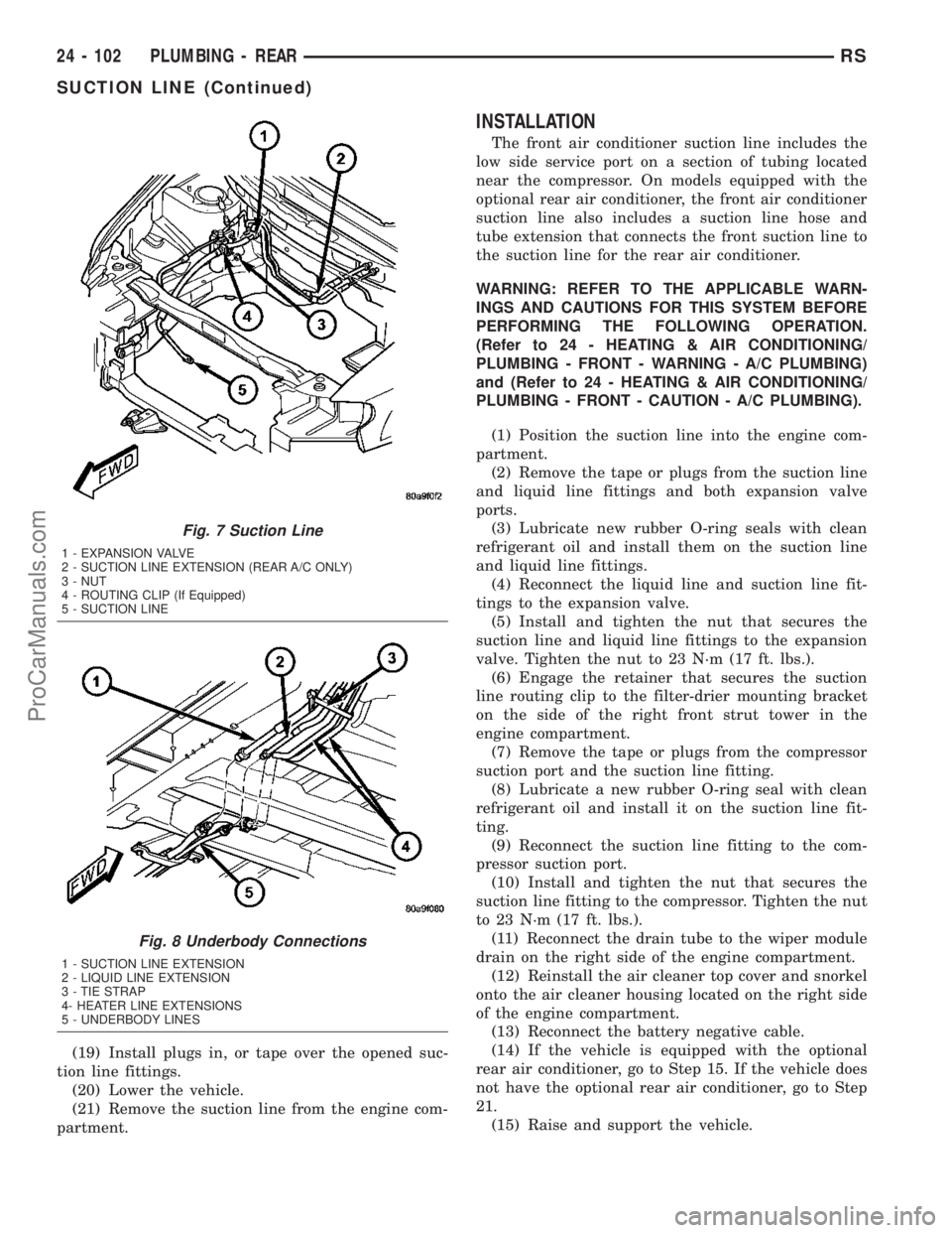
engine compartment (Fig. 7).
(10) Remove the nut that secures the suction line
and liquid line fittings to the expansion valve.
(11) Disconnect the suction line and liquid line fit-
tings from the expansion valve.
(12) Remove the seals from the suction line and
liquid line fittings and discard.
(13) Install plugs in, or tape over the opened suc-
tion line and liquid line fittings and both expansion
valve ports.
(14) If the vehicle is equipped with the optional
rear air conditioner, go to Step 15. If the vehicle does
not have the optional rear air conditioner, go to Step
21.
(15) Raise and support the vehicle.
(16) Cut the tie strap located just forward of the
connections between the underbody plumbing and
the engine compartment plumbing for the rear
heater and air conditioner (Fig. 8).
(17) Disconnect the suction line extension fitting
from the underbody suction line fitting for the rear
air conditioner.
(18) Remove the seal from the underbody suction
line fitting and discard.
RSPLUMBING - REAR24 - 101
HEATER HOSE (Continued)
ProCarManuals.com
Page 2099 of 2177
(19) Install plugs in, or tape over the opened suc-
tion line fittings.
(20) Lower the vehicle.
(21) Remove the suction line from the engine com-
partment.
INSTALLATION
The front air conditioner suction line includes the
low side service port on a section of tubing located
near the compressor. On models equipped with the
optional rear air conditioner, the front air conditioner
suction line also includes a suction line hose and
tube extension that connects the front suction line to
the suction line for the rear air conditioner.
WARNING: REFER TO THE APPLICABLE WARN-
INGS AND CAUTIONS FOR THIS SYSTEM BEFORE
PERFORMING THE FOLLOWING OPERATION.
(Refer to 24 - HEATING & AIR CONDITIONING/
PLUMBING - FRONT - WARNING - A/C PLUMBING)
and (Refer to 24 - HEATING & AIR CONDITIONING/
PLUMBING - FRONT - CAUTION - A/C PLUMBING).
(1) Position the suction line into the engine com-
partment.
(2) Remove the tape or plugs from the suction line
and liquid line fittings and both expansion valve
ports.
(3) Lubricate new rubber O-ring seals with clean
refrigerant oil and install them on the suction line
and liquid line fittings.
(4) Reconnect the liquid line and suction line fit-
tings to the expansion valve.
(5) Install and tighten the nut that secures the
suction line and liquid line fittings to the expansion
valve. Tighten the nut to 23 N´m (17 ft. lbs.).
(6) Engage the retainer that secures the suction
line routing clip to the filter-drier mounting bracket
on the side of the right front strut tower in the
engine compartment.
(7) Remove the tape or plugs from the compressor
suction port and the suction line fitting.
(8) Lubricate a new rubber O-ring seal with clean
refrigerant oil and install it on the suction line fit-
ting.
(9) Reconnect the suction line fitting to the com-
pressor suction port.
(10) Install and tighten the nut that secures the
suction line fitting to the compressor. Tighten the nut
to 23 N´m (17 ft. lbs.).
(11) Reconnect the drain tube to the wiper module
drain on the right side of the engine compartment.
(12) Reinstall the air cleaner top cover and snorkel
onto the air cleaner housing located on the right side
of the engine compartment.
(13) Reconnect the battery negative cable.
(14) If the vehicle is equipped with the optional
rear air conditioner, go to Step 15. If the vehicle does
not have the optional rear air conditioner, go to Step
21.
(15) Raise and support the vehicle.
Fig. 7 Suction Line
1 - EXPANSION VALVE
2 - SUCTION LINE EXTENSION (REAR A/C ONLY)
3 - NUT
4 - ROUTING CLIP (If Equipped)
5 - SUCTION LINE
Fig. 8 Underbody Connections
1 - SUCTION LINE EXTENSION
2 - LIQUID LINE EXTENSION
3 - TIE STRAP
4- HEATER LINE EXTENSIONS
5 - UNDERBODY LINES
24 - 102 PLUMBING - REARRS
SUCTION LINE (Continued)
ProCarManuals.com
Page 2100 of 2177
(16) Remove the tape or plugs from the suction
line extension fitting and the underbody suction line
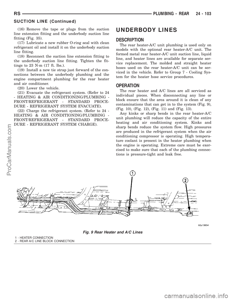
fitting (Fig. 35).
(17) Lubricate a new rubber O-ring seal with clean
refrigerant oil and install it on the underbody suction
line fitting.
(18) Reconnect the suction line extension fitting to
the underbody suction line fitting. Tighten the fit-
tings to 23 N´m (17 ft. lbs.).
(19) Install a new tie strap just forward of the con-
nections between the underbody plumbing and the
engine compartment plumbing for the rear heater
and air conditioner.
(20) Lower the vehicle.
(21) Evacuate the refrigerant system. (Refer to 24
- HEATING & AIR CONDITIONING/PLUMBING -
FRONT/REFRIGERANT - STANDARD PROCE-
DURE - REFRIGERANT SYSTEM EVACUATE).
(22) Charge the refrigerant system. (Refer to 24 -
HEATING & AIR CONDITIONING/PLUMBING -
FRONT/REFRIGERANT - STANDARD PROCE-
DURE - REFRIGERANT SYSTEM CHARGE).UNDERBODY LINES
DESCRIPTION
The rear heater-A/C unit plumbing is used only on
models with the optional rear heater-A/C unit. The
formed metal rear heater-A/C unit suction line, liquid
line, and heater lines are available for separate ser-
vice replacement. The molded and straight heater
hoses used on the rear heater-A/C unit can be ser-
viced in the vehicle. Refer to Group 7 - Cooling Sys-
tem for the heater hose service procedures.
OPERATION
The rear heater and A/C lines are all serviced as
individual pieces. When disconnecting any line or
block ensure that the area around it is clean of any
contaminations that can get in to the system (Fig. 9),
(Fig. 10), (Fig. 12), (Fig. 11) and (Fig. 13).
Any kinks or sharp bends in the rear heater-A/C
unit plumbing will reduce the capacity of the entire
heating and air conditioning system. Kinks and
sharp bends reduce the system flow. High pressures
are produced in the refrigerant system when the air
conditioning compressor is operating. High tempera-
ture coolant is present in the heater plumbing when
the engine is operating. Extreme care must be exer-
cised to make sure that each of the plumbing connec-
tions is pressure-tight and leak free.
Fig. 9 Rear Heater and A/C Lines
1 - HEATER CONNECTION
2 - REAR A/C LINE BLOCK CONNECTION
RSPLUMBING - REAR24 - 103
SUCTION LINE (Continued)
ProCarManuals.com
Page 2116 of 2177
period the switch ratio reaches a predetermined
value, a counter is incremented by one. The monitor
is enabled to run another test during that trip. When
the test fails 6 times, the counter increments to 3, a
malfunction is entered, and a Freeze Frame is stored,
the code is matured and the MIL is illuminated. If
the first test passes, no further testing is conducted
during that trip.
The MIL is extinguished after three consecutive
good trips. The good trip criteria for the catalyst
monitor is more stringent than the failure criteria. In
order to pass the test and increment one good trip,
the downstream sensor switch rate must be less than
45% of the upstream rate. The failure percentages
are 59% respectively.
Enabling ConditionsÐThe following conditions
must typically be met before the PCM runs the cat-
alyst monitor. Specific times for each parameter may
be different from engine to engine.
²Accumulated drive time
²Enable time
²Ambient air temperature
²Barometric pressure
²Catalyst warm-up counter
²Engine coolant temperature
²Vehicle speed
²MAP
²RPM
²Engine in closed loop
²Fuel level
Pending ConditionsÐ
²Misfire DTC
²Front Oxygen Sensor Response
²Front Oxygen Sensor Heater Monitor
²Front Oxygen Sensor Electrical
²Rear Oxygen Sensor Rationality (middle check)
²Rear Oxygen Sensor Heater Monitor
²Rear Oxygen Sensor Electrical
²Fuel System Monitor
²All TPS faults
²All MAP faults
²All ECT sensor faults
²Purge flow solenoid functionality
²Purge flow solenoid electrical
²All PCM self test faults
²All CMP and CKP sensor faults
²All injector and ignition electrical faults
²Idle Air Control (IAC) motor functionality
²Vehicle Speed Sensor
²Brake switch (auto trans only)
²Intake air temperature
ConflictÐThe catalyst monitor does not run if any
of the following are conditions are present:
²EGR Monitor in progress (if equipped)
²Fuel system rich intrusive test in progress
²EVAP Monitor in progress²Time since start is less than 60 seconds
²Low fuel level-less than 15 %
²Low ambient air temperature
²Ethanol content learn is taking place and the
ethanol used once flag is set
SuspendÐThe Task Manager does not mature a
catalyst fault if any of the following are present:
²Oxygen Sensor Monitor, Priority 1
²Oxygen Sensor Heater, Priority 1
²EGR Monitor, Priority 1 (if equipped)
²EVAP Monitor, Priority 1
²Fuel System Monitor, Priority 2
²Misfire Monitor, Priority 2
OPERATION - NON-MONITORED CIRCUITS
The PCM does not monitor all circuits, systems
and conditions that could have malfunctions causing
driveability problems. However, problems with these
systems may cause the PCM to store diagnostic trou-
ble codes for other systems or components. For exam-
ple, a fuel pressure problem will not register a fault
directly, but could cause a rich/lean condition or mis-
fire. This could cause the PCM to store an oxygen
sensor or misfire diagnostic trouble code.
The major non-monitored circuits are listed below
along with examples of failures modes that do not
directly cause the PCM to set a DTC, but for a sys-
tem that is monitored.
FUEL PRESSURE
The fuel pressure regulator controls fuel system
pressure. The PCM cannot detect a clogged fuel
pump inlet filter, clogged in-line fuel filter, or a
pinched fuel supply or return line. However, these
could result in a rich or lean condition causing the
PCM to store an oxygen sensor, fuel system, or mis-
fire diagnostic trouble code.
SECONDARY IGNITION CIRCUIT
The PCM cannot detect an inoperative ignition coil,
fouled or worn spark plugs, ignition cross firing, or
open spark plug cables. The misfire will however,
increase the oxygen content in the exhaust, deceiving
the PCM in to thinking the fuel system is too lean.
Also see misfire detection.
CYLINDER COMPRESSION
The PCM cannot detect uneven, low, or high engine
cylinder compression. Low compression lowers O2
content in the exhaust. Leading to fuel system, oxy-
gen sensor, or misfire detection fault.
EXHAUST SYSTEM
The PCM cannot detect a plugged, restricted or
leaking exhaust system. It may set a EGR (if
equipped) or Fuel system or O2S fault.
RSEMISSIONS CONTROL25-5
EMISSIONS CONTROL (Continued)
ProCarManuals.com
Page 2120 of 2177
OPERATION
OPERATION - SYSTEM
The Powertrain Control Module (PCM) monitors
many different circuits in the fuel injection, ignition,
emission and engine systems. If the PCM senses a
problem with a monitored circuit often enough to
indicate an actual problem, it stores a Diagnostic
Trouble Code (DTC) in the PCM's memory. If the
code applies to a non-emissions related component or
system, and the problem is repaired or ceases to
exist, the PCM cancels the code after 40 warmup
cycles. Diagnostic trouble codes that affect vehicle
emissions illuminate the Malfunction Indicator Lamp
(MIL). Refer to Malfunction Indicator Lamp in this
section.
Certain criteria must be met before the PCM
stores a DTC in memory. The criteria may be a spe-
cific range of engine RPM, engine temperature,
and/or input voltage to the PCM.
The PCM might not store a DTC for a monitored
circuit even though a malfunction has occurred. This
may happen because one of the DTC criteria for the
circuit has not been met.For example, assume the
diagnostic trouble code criteria requires the PCM to
monitor the circuit only when the engine operates
between 750 and 2000 RPM. Suppose the sensor's
output circuit shorts to ground when engine operates
above 2400 RPM (resulting in 0 volt input to the
PCM). Because the condition happens at an engine
speed above the maximum threshold (2000 rpm), the
PCM will not store a DTC.
There are several operating conditions for which
the PCM monitors and sets DTC's. Refer to Moni-
tored Systems, Components, and Non-Monitored Cir-
cuits in this section.
NOTE: Various diagnostic procedures may actually
cause a diagnostic monitor to set a DTC. For
instance, pulling a spark plug wire to perform a
spark test may set the misfire code. When a repair
is completed and verified, use the DRBIIITscan tool
to erase all DTC's and extinguish the MIL.Technicians can display stored DTC's. Refer to
Diagnostic Trouble Codes (Refer to 8 - ELECTRICAL/
ELECTRONIC CONTROL MODULES/POWER-
TRAIN CONTROL MODULE - DESCRIPTION). For
obtaining the DTC information, use the Data Link
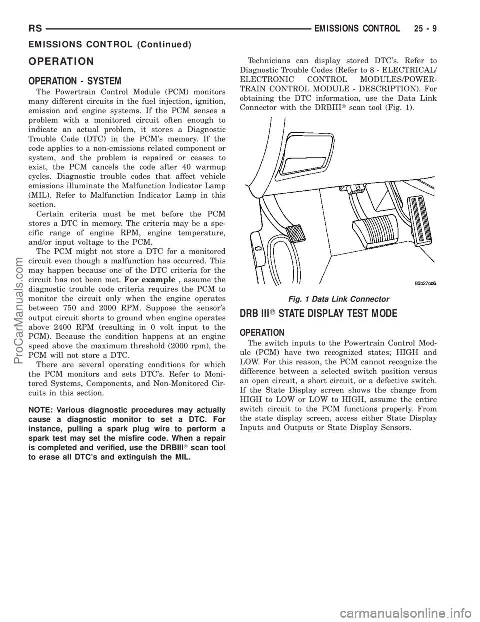
Connector with the DRBIIItscan tool (Fig. 1).
DRB IIITSTATE DISPLAY TEST MODE
OPERATION
The switch inputs to the Powertrain Control Mod-
ule (PCM) have two recognized states; HIGH and
LOW. For this reason, the PCM cannot recognize the
difference between a selected switch position versus
an open circuit, a short circuit, or a defective switch.
If the State Display screen shows the change from
HIGH to LOW or LOW to HIGH, assume the entire
switch circuit to the PCM functions properly. From
the state display screen, access either State Display
Inputs and Outputs or State Display Sensors.
Fig. 1 Data Link Connector
RSEMISSIONS CONTROL25-9
EMISSIONS CONTROL (Continued)
ProCarManuals.com
Page 2148 of 2177
CUSHION SIDE COVER - INSTALLATION,
FRONT SEAT........................23-93
CUSHION SIDE COVER - REMOVAL,
FRONT SEAT........................23-93
CV BOOT - INNER - INSTALLATION........3-6
CV BOOT - INNER - REMOVAL............3-6
CV BOOT - INNER/OUTER -
INSTALLATION........................3-17
CV BOOT - INNER/OUTER - REMOVAL.....3-15
CV BOOT - OUTER - INSTALLATION.......3-10
CV BOOT - OUTER - REMOVAL...........3-10
CYCLE - STANDARD PROCEDURE,
POWER DOOR LEARN................8N-28
CYCLE - STANDARD PROCEDURE,
POWER LIFTGATE LEARN...............8N-9
CYLINDER - DESCRIPTION, KEY/LOCK....19-20
CYLINDER - DESCRIPTION, STANDARD 4 . . . 8I-9
CYLINDER - INSTALLATION, KEY/LOCK . . . 19-20
CYLINDER - INSTALLATION, LOCK . . 23-20,23-41
CYLINDER - INSTALLATION, SLAVE.......6-11
CYLINDER - INSTALLATION, SUPPORT....23-42
CYLINDER - LHD - INSTALLATION,
MASTER............................6-10
CYLINDER - LHD - REMOVAL, MASTER.....6-9
CYLINDER - OPERATION, KEY/LOCK......19-20
CYLINDER - REMOVAL, KEY/LOCK.......19-20
CYLINDER - REMOVAL, LOCK......23-19,23-41
CYLINDER - REMOVAL, SLAVE...........6-11
CYLINDER - REMOVAL, SUPPORT.......23-42
CYLINDER - RHD - INSTALLATION,
MASTER.............................6-9
CYLINDER - RHD - REMOVAL, MASTER.....6-8
CYLINDER BLEEDING - STANDARD
PROCEDURE, MASTER.................5-35
CYLINDER BORE FITTING - STANDARD
PROCEDURE, PISTON TO...............9-42
CYLINDER BORE HONING - STANDARD
PROCEDURE....................9-112,9-35
CYLINDER COMBUSTION PRESSURE
LEAKAGE TEST - DIAGNOSIS AND
TESTING.........................9-83,9-9
CYLINDER COMPRESSION PRESSURE
TEST - DIAGNOSIS AND TESTING.....9-83,9-9
CYLINDER (FLUID RESERVOIR) -
ASSEMBLY, MASTER...................5-38
CYLINDER (FLUID RESERVOIR) -
DISASSEMBLY, MASTER................5-37
CYLINDER HEAD - CLEANING.......9-100,9-26
CYLINDER HEAD - DESCRIPTION.....9-24,9-99
CYLINDER HEAD - INSPECTION.....9-101,9-26
CYLINDER HEAD - INSTALLATION . . . 9-101,9-26
CYLINDER HEAD - REMOVAL.......9-100,9-25
CYLINDER HEAD COVER - CLEANING......9-31
CYLINDER HEAD COVER - INSPECTION....9-31
CYLINDER HEAD COVER -
INSTALLATION........................9-31
CYLINDER HEAD COVER - LEFT -
INSTALLATION.......................9-103
CYLINDER HEAD COVER - LEFT -
REMOVAL..........................9-103
CYLINDER HEAD COVER - REMOVAL......9-31
CYLINDER HEAD COVER - RIGHT -
INSTALLATION.......................9-103
CYLINDER HEAD COVER - RIGHT -
REMOVAL..........................9-102
CYLINDER HEAD COVER(S) -
DESCRIPTION.......................9-102
CYLINDER HEAD GASKET - DIAGNOSIS
AND TESTING....................9-24,9-99
CYLINDER HEAD OFF - INSTALLATION . . . 9-108,
9-33
CYLINDER HEAD OFF - REMOVAL . . . 9-106,9-32
CYLINDER HEAD ON - INSTALLATION....9-108,
9-33
CYLINDER HEAD ON - REMOVAL....9-106,9-32
CYLINDER HOUSING - INSTALLATION,
LOCK..............................19-19
CYLINDER HOUSING - REMOVAL, LOCK . . 19-17
CYLINDER LOCK SWITCH -
DESCRIPTION, DOOR
.................8N-40
CYLINDER LOCK SWITCH - DIAGNOSIS
AND TESTING, DOOR
.................8N-40
CYLINDER LOCK SWITCH -
INSTALLATION, DOOR
.................8N-41
CYLINDER LOCK SWITCH - OPERATION,
DOOR
.............................8N-40
CYLINDER LOCK SWITCH - REMOVAL,
DOOR
.............................8N-41CYLINDERS - INSPECTION, WHEEL.......5-57
CYLINDERS - INSTALLATION, WHEEL.....5-57
CYLINDERS - REMOVAL, WHEEL.........5-57
DAMAGED OR WORN THREADS -
STANDARD PROCEDURE, REPAIR OF . . 9-10,9-86
DAMPER - INSTALLATION, VIBRATION . . . 9-130,
9-47
DAMPER - REMOVAL, VIBRATION . . . 9-130,9-47
DATA BUS COMMUNICATION RECEIVE -
PCM INPUT - OPERATION..............8E-15
DATA LINK CONNECTOR - DESCRIPTION . . . 8E-6
DATA LINK CONNECTOR - OPERATION.....8E-7
DAY / NIGHT MIRROR - DESCRIPTION,
AUTOMATIC........................8N-47
DAY / NIGHT MIRROR - DIAGNOSIS AND
TESTING, AUTOMATIC................8N-47
DAY / NIGHT MIRROR - OPERATION,
AUTOMATIC........................8N-47
DCHA - DIAGNOSIS AND TESTING,
DIESEL SUPPLEMENTAL HEATER.......24-107
DCHA - EXPORT - DESCRIPTION, DIESEL
SUPPLEMENTAL HEATER.............24-106
DEAERATION - DIAGNOSIS AND
TESTING, COOLING SYSTEM.............7-4
DECOUPLER PULLEY - DESCRIPTION,
GENERATOR........................8F-25
DECOUPLER PULLEY - DIAGNOSIS AND
TESTING, GENERATOR................8F-25
DECOUPLER PULLEY - INSTALLATION,
GENERATOR........................8F-26
DECOUPLER PULLEY - OPERATION,
GENERATOR..........................8F-25
DECOUPLER PULLEY - REMOVAL,
GENERATOR........................8F-26
DEFINITION - DESCRIPTION, TRIP........25-1
DEFLECTOR - INSTALLATION, WIND.....23-118
DEFLECTOR - REMOVAL, WIND........23-118
DEFOGGER RELAY - DESCRIPTION.......8G-2
DEFOGGER SWITCH - DESCRIPTION,
REAR WINDOW.......................8G-2
DEFOGGER SWITCH - OPERATION, REAR
WINDOW............................8G-2
DEFROSTER DUCT - INSTALLATION......24-48
DEFROSTER DUCT - REMOVAL..........24-47
DEMAGNETIZING - STANDARD
PROCEDURE, COMPASS...............8M-4
DEMISTER DUCTS - INSTALLATION......24-48
DEMISTER DUCTS - REMOVAL..........24-48
DEMISTER OUTLET - INSTALLATION.....24-42
DEMISTER OUTLET - REMOVAL.........24-41
DEPLOYMENT - STANDARD
PROCEDURE, SERVICE AFTER AN
AIRBAG.............................8O-3
DETECTION ASSY - INSTALLATION,
NATURAL VAC LEAK..................25-13
DETECTION ASSY - REMOVAL, NATURAL
VAC LEAK..........................25-13
DETECTION PUMP - INSTALLATION,
LEAK..............................25-13
DETECTION PUMP - REMOVAL, LEAK....25-13
DEVICES - STANDARD PROCEDURE,
ELECTROSTATIC DISCHARGE (ESD)
SENSITIVE........................8W-01-8
DIAGNOSTIC SYSTEM - DIAGNOSIS AND
TESTING, ON-BOARD.................8F-21
DIAGNOSTIC TROUBLE CODES -
STANDARD PROCEDURE, OBTAINING.....8E-15
DIAGRAMS - 41TE TRANSAXLE
HYDRAULIC SCHEMATICS,
SCHEMATICS.......................21-169
DIAGRAMS - DESCRIPTION, HOW TO
USE WIRING......................8W-01-1
DIESEL - DESCRIPTION, 2.5L...........19-51
DIESEL - INSTALLATION, 2.5L..........19-52
DIESEL - REMOVAL, 2.5L..............19-51
DIESEL ENGINE - DESCRIPTION, FUEL
REQUIREMENTS.......................0-6
DIESEL ENGINES - DESCRIPTION,
ENGINE OIL...........................0-6
DIESEL HEATER WIRING -
INSTALLATION, SUPPLEMENTAL
........24-112
DIESEL HEATER WIRING - REMOVAL,
SUPPLEMENTAL
....................24-112
DIESEL SUPPLEMENTAL HEATER - DCHA
- DIAGNOSIS AND TESTING
...........24-107
DIESEL SUPPLEMENTAL HEATER - DCHA
- EXPORT - DESCRIPTION
............24-106
DIFFERENTIAL - ASSEMBLY
............21-66DIFFERENTIAL - DESCRIPTION..........21-62
DIFFERENTIAL - DISASSEMBLY.........21-62
DIFFERENTIAL - OPERATION............21-62
DIFFERENTIAL ASSEMBLY -
DESCRIPTION........................3-39
DIFFERENTIAL ASSEMBLY - OPERATION . . . 3-39
DIFFERENTIAL ASSEMBLY FLUID
CHANGE - STANDARD PROCEDURE.......3-40
DIFFERENTIAL BEARING PRELOAD -
ADJUSTMENT......................21-199
DIFFERENTIAL CARRIER SEAL -
INSTALLATION........................21-9
DIFFERENTIAL CARRIER SEAL -
REMOVAL...........................21-9
DIFFERENTIAL SIDE GEAR END PLAY -
ADJUSTMENT.......................21-70
DIFFERENTIAL TURNING TORQUE -
ADJUSTMENT.......................21-69
DIMENSIONS - SPECIFICATIONS, BODY
OPENING..........................23-124
DIMENSIONS, SPECIFICATIONS - FRAME . . . 13-4
DIODE - INSTALLATION............8W-01-14
DIODE - REMOVAL................8W-01-14
DISC AND PRESSURE PLATE - 2.5L TD -
INSTALLATION, CLUTCH................6-12
DISC AND PRESSURE PLATE - 2.5L TD -
REMOVAL, CLUTCH....................6-11
DISC BRAKE CALIPER - INSTALLATION,
REAR...............................5-30
DISC BRAKE CALIPER - REMOVAL,
REAR...............................5-27
DISC BRAKE CALIPER ADAPTER -
INSTALLATION, FRONT.................5-31
DISC BRAKE CALIPER ADAPTER -
REMOVAL, FRONT.....................5-31
DISC BRAKE CALIPER (DISC/DISC
BRAKES) - INSTALLATION, FRONT........5-27
DISC BRAKE CALIPER (DISC/DISC
BRAKES) - REMOVAL, FRONT............5-24
DISC BRAKE CALIPER (DISC/DRUM
BRAKES) - INSTALLATION, FRONT........5-27
DISC BRAKE CALIPER (DISC/DRUM
BRAKES) - REMOVAL, FRONT............5-24
DISC BRAKE CALIPER GUIDE PINS
(DISC/DRUM BRAKES) -
INSTALLATION........................5-31
DISC BRAKE CALIPER GUIDE PINS
(DISC/DRUM BRAKES) - REMOVAL.......5-31
DISC BRAKE SHOES - CLEANING.....5-16,5-18
DISC BRAKE SHOES - INSPECTION . . . 5-16,5-18
DISC BRAKE SHOES - INSTALLATION,
REAR...............................5-19
DISC BRAKE SHOES - REMOVAL, REAR....5-17
DISC BRAKE SHOES (DISC/DISC
BRAKES) - INSTALLATION, FRONT........5-16
DISC BRAKE SHOES (DISC/DISC
BRAKES) - REMOVAL, FRONT............5-14
DISC BRAKE SHOES (DISC/DRUM
BRAKES) - INSTALLATION, FRONT........5-17
DISC BRAKE SHOES (DISC/DRUM
BRAKES) - REMOVAL, FRONT............5-15
DISC BRAKES (EXPORT) - DESCRIPTION . . . 5-13
DISC BRAKES (FRONT) - DESCRIPTION....5-11
DISC BRAKES (FRONT) - OPERATION......5-13
DISC BRAKES (REAR) - DESCRIPTION.....5-12
DISC BRAKES (REAR) - OPERATION......5-13
DISC RUNOUT - DIAGNOSIS AND
TESTING, CLUTCH COVER...............6-6
DISCHARGE (ESD) SENSITIVE DEVICES -
STANDARD PROCEDURE,
ELECTROSTATIC...................8W-01-8
DISCHARGE LINE - INSTALLATION.......24-69
DISCHARGE LINE - REMOVAL..........24-68
DISPLAY TEST MODE, OPERATION - DRB
IIITSTATE ...........................25-9
DISTRIBUTION DUCT - INSTALLATION,
A/C................................24-53
DISTRIBUTION DUCT - INSTALLATION,
REAR HEATER.......................24-59
DISTRIBUTION DUCT - REMOVAL, A/C
....24-53
DISTRIBUTION DUCT - REMOVAL, REAR
HEATER
............................24-59
DISTRIBUTION DUCTS - INSTALLATION,
FLOOR
.............................24-49
DISTRIBUTION DUCTS - REMOVAL,
FLOOR
.............................24-48
DISTRIBUTION SYSTEM - DESCRIPTION,
POWER
..........................8W-97-1
RSINDEX9
Description Group-Page Description Group-Page Description Group-Page
ProCarManuals.com
Page 2155 of 2177
HINGE - INSTALLATION, LOWER........23-28
HINGE - INSTALLATION, UPPER.........23-35
HINGE - REMOVAL.........23-18,23-39,23-59
HINGE - REMOVAL, BENCH SEAT BACK . . 23-100
HINGE - REMOVAL, CENTER............23-24
HINGE - REMOVAL, LOWER............23-28
HINGE - REMOVAL, UPPER.............23-35
HINGE COVERS - QUAD BUCKET, 50/50
SPLIT, BENCH - INSTALLATION, SEAT
BACK.............................23-100
HINGE COVERS - QUAD BUCKET, 50/50
SPLIT, BENCH - REMOVAL, SEAT BACK . . 23-100
HOISTING - STANDARD PROCEDURE......0-15
HOLD OPEN LATCH - INSTALLATION.....23-25
HOLD OPEN LATCH - REMOVAL.........23-25
HOLD OPEN LATCH CABLE -
INSTALLATION.......................23-38
HOLD OPEN LATCH CABLE - REMOVAL . . . 23-37
HOLD OPEN LATCH STRIKER -
INSTALLATION.......................23-26
HOLD OPEN LATCH STRIKER -
REMOVAL..........................23-26
HOLDDOWN - DESCRIPTION, BATTERY . . . 8F-15
HOLDDOWN - INSTALLATION, BATTERY . . . 8F-16
HOLDDOWN - OPERATION, BATTERY.....8F-15
HOLDDOWN - REMOVAL, BATTERY......8F-16
HOLDER - INSTALLATION, CUP.........23-63
HOLDER - INSTALLATION, QUAD
BUCKET SEAT SIDE SHIELD - NO CUP.....23-96
HOLDER - INSTALLATION, QUAD
BUCKET SEAT SIDE SHIELD/CUP........23-95
HOLDER - REMOVAL, CUP.............23-63
HOLDER - REMOVAL, QUAD BUCKET
SEAT SIDE SHIELD - NO CUP...........23-96
HOLDER - REMOVAL, QUAD BUCKET
SEAT SIDE SHIELD/CUP...............23-95
HOLDING CLUTCHES - DESCRIPTION....21-207
HOLDING CLUTCHES - OPERATION.....21-207
HOLE REPAIR - DESCRIPTION,
THREADED........................Intro.-5
HONING - STANDARD PROCEDURE,
CYLINDER BORE.................9-112,9-35
HOOD - INSTALLATION................23-60
HOOD - REMOVAL....................23-59
HOOD AJAR SWITCH - EXPORT -
INSTALLATION.......................8Q-3
HOOD AJAR SWITCH - EXPORT -
REMOVAL...........................8Q-3
HORN - DIAGNOSIS AND TESTING.......8H-3
HORN - INSTALLATION.................8H-5
HORN - REMOVAL....................8H-5
HORN CHIRP PREFERENCE - STANDARD
PROCEDURE........................8N-42
HORN RELAY - DIAGNOSIS AND
TESTING............................8H-5
HORN RELAY - INSTALLATION...........8H-5
HORN RELAY - REMOVAL..............8H-5
HORN SWITCH - DESCRIPTION..........8H-5
HORN SYSTEM - DESCRIPTION..........8H-1
HORN SYSTEM - DIAGNOSIS AND
TESTING............................8H-1
HORN SYSTEM - OPERATION............8H-1
HOSE - EXPORT - INSTALLATION,
HEADLAMP WASHER.................8R-12
HOSE - EXPORT - REMOVAL, HEADLAMP
WASHER...........................8R-12
HOSE - INSTALLATION, HEATER . . . 24-101,24-80
HOSE - REMOVAL, HEATER......24-100,24-78
HOSE CLAMPS - DESCRIPTION...........7-1
HOSE CLAMPS - OPERATION.............7-2
HOSES - DESCRIPTION, BRAKE TUBES
....5-14
HOSES - INSPECTION, BRAKE TUBES
.....5-14
HOSES - INSTALLATION, WASHER
.......8R-16
HOSES - OPERATION, BRAKE TUBES
......5-14
HOSES - REMOVAL, WASHER
..........8R-16
HOSES AND CLAMP - STANDARD
PROCEDURE
.........................14-6
HOUSING - INSTALLATION, AIR
CLEANER
........................9-24,9-99
HOUSING - INSTALLATION, HVAC
........24-50
HOUSING - INSTALLATION, LOCK
CYLINDER
..........................19-19
HOUSING - INSTALLATION, REAR
HEATER-A/C
.........................24-58
HOUSING - REMOVAL, AIR CLEANER
. . 9-24,9-99
HOUSING - REMOVAL, HVAC
...........24-49
HOUSING - REMOVAL, LOCK CYLINDER
. . 19-17HOUSING - REMOVAL, REAR HEATER-A/
C .................................24-56
HOUSING FLUID CHANGE - STANDARD
PROCEDURE, OVERRUNNING CLUTCH.....3-41
HOUSING FLUID LEAKAGE - DIAGNOSIS
AND TESTING, TORQUE CONVERTER....21-123
HOW TO USE WIRING DIAGRAMS -
DESCRIPTION.....................8W-01-1
HUB / BEARING - DESCRIPTION.......2-30,2-5
HUB / BEARING - INSTALLATION......2-32,2-5
HUB / BEARING - OPERATION........2-30,2-5
HUB / BEARING - REMOVAL..........2-31,2-5
HUB AND BEARING - DIAGNOSIS AND
TESTING.........................2-30,2-5
HVAC - LWB - INSTALLATION, SEAT
BELT & RETRACTOR - SECOND ROW -
RIGHT OUTBOARD WITH REAR.........8O-15
HVAC - LWB - REMOVAL, SEAT BELT &
RETRACTOR - SECOND ROW - RIGHT
OUTBOARD WITH REAR...............8O-15
HVAC HOUSING - INSTALLATION........24-50
HVAC HOUSING - REMOVAL............24-49
HVAC LOUVER - INSTALLATION, REAR . . . 23-79
HVAC LOUVER - REMOVAL, REAR.......23-79
HYDRAULIC CIRCUITS AND VALVES -
OPERATION..........................5-83
HYDRAULIC LASH ADJUSTER NOISE
DIAGNOSIS - DIAGNOSIS AND
TESTING............................9-34
HYDRAULIC LASH ADJUSTERS -
INSTALLATION........................9-34
HYDRAULIC LASH ADJUSTERS -
REMOVAL...........................9-34
HYDRAULIC LIFTERS - DIAGNOSIS AND
TESTING...........................9-113
HYDRAULIC LIFTERS (CAM IN BLOCK) -
DESCRIPTION.......................9-113
HYDRAULIC LIFTERS (CAM IN BLOCK) -
INSTALLATION.......................9-114
HYDRAULIC LIFTERS (CAM IN BLOCK) -
REMOVAL..........................9-114
HYDRAULIC PRESSURE TESTS -
DIAGNOSIS AND TESTING............21-120
HYDRAULIC SCHEMATICS, SCHEMATICS
AND DIAGRAMS - 41TE TRANSAXLE....21-169
HYDROSTATIC LOCKED ENGINE -
STANDARD PROCEDURE............9-10,9-85
ICU - ASSEMBLY......................5-94
ICU - DISASSEMBLY...................5-93
ICU (INTEGRATED CONTROL UNIT) -
DESCRIPTION........................5-89
ICU (INTEGRATED CONTROL UNIT) -
OPERATION..........................5-90
IDENTIFICATION - DESCRIPTION,
FASTENER.........................Intro.-2
IDENTIFICATION - DESCRIPTION,
VEHICLE............................23-1
IDENTIFICATION AND INFORMATION -
DESCRIPTION, SECTION.............8W-01-6
IDENTIFICATION, DIAGNOSIS AND
TESTING - SEAL......................21-3
IDENTIFICATION NUMBER -
DESCRIPTION, VEHICLE..............Intro.-9
IDLE AIR CONTROL MOTOR -
DESCRIPTION.......................14-28
IDLE AIR CONTROL MOTOR -
INSTALLATION.......................14-29
IDLE AIR CONTROL MOTOR -
OPERATION.........................14-28
IDLE AIR CONTROL MOTOR - REMOVAL
. . 14-29
IGNITION COIL - DESCRIPTION
...........8I-6
IGNITION COIL - OPERATION
.............8I-6
IGNITION INTERLOCK - DESCRIPTION
....19-17
IGNITION SENSE - PCM INPUT -
OPERATION
.........................8E-15
IGNITION SWITCH - INSTALLATION
......19-16
IGNITION SWITCH - REMOVAL
..........19-14
IGNITION SYSTEM - DESCRIPTION
........8I-1
IGNITION SYSTEM - OPERATION
..........8I-1
IGNITION-OFF DRAW TEST - STANDARD
PROCEDURE
........................8F-13
IIITSTATE DISPLAY TEST MODE,
OPERATION - DRB
....................25-9
ILLUMINATION LAMPS - INSTALLATION,
CLUSTER
...........................8L-26
ILLUMINATION LAMPS - REMOVAL,
CLUSTER
...........................8L-26IMMOBILIZER MODULE - DESCRIPTION,
SENTRY KEY........................8E-18
IMMOBILIZER MODULE - INSTALLATION,
SENTRY KEY........................8E-19
IMMOBILIZER MODULE - OPERATION,
SENTRY KEY........................8E-18
IMMOBILIZER MODULE - REMOVAL,
SENTRY KEY........................8E-18
IMMOBILIZER SYSTEM - DIAGNOSIS
AND TESTING, SENTRY KEY.............8Q-3
IMPACT AIRBAG CONTROL MODULE -
DESCRIPTION, SIDE..................8O-17
IMPACT AIRBAG CONTROL MODULE -
INSTALLATION, SIDE.................8O-17
IMPACT AIRBAG CONTROL MODULE -
OPERATION, SIDE....................8O-17
IMPACT AIRBAG CONTROL MODULE -
REMOVAL, SIDE.....................8O-17
INBOARD - 50/50 BENCH -
INSTALLATION, SEAT BELT BUCKLE -
SECOND ROW.......................8O-12
INBOARD - 50/50 BENCH - REMOVAL,
SEAT BELT BUCKLE - SECOND ROW.....8O-12
INBOARD - INSTALLATION, SEAT BELT
BUCKLE - FRONT....................8O-11
INBOARD - QUAD BUCKET -
INSTALLATION, SEAT BELT BUCKLE -
FIRST ROW.........................8O-11
INBOARD - QUAD BUCKET - REMOVAL,
SEAT BELT BUCKLE - FIRST ROW.......8O-11
INBOARD - REMOVAL, SEAT BELT
BUCKLE - FRONT....................8O-11
INDICATOR LAMP - DESCRIPTION,
VTSS/SKIS..........................8Q-5
INDICATOR LAMP - OPERATION,
VTSS/SKIS..........................8Q-5
INDICATORS - DIAGNOSIS AND
TESTING, TREAD WEAR...............22-16
INFLATION PRESSURES - STANDARD
PROCEDURE, TIRE...................22-16
INFO CENTER - DESCRIPTION,
ELECTRONIC VEHICLE.................8M-6
INFO CENTER - INSTALLATION,
ELECTRONIC VEHICLE.................8M-9
INFO CENTER - OPERATION,
ELECTRONIC VEHICLE.................8M-7
INFO CENTER - REMOVAL, ELECTRONIC
VEHICLE............................8M-9
INFRARED TEMPERATURE SENSOR -
DESCRIPTION..................24-23,24-35
INFRARED TEMPERATURE SENSOR -
OPERATION....................24-24,24-35
INITIAL OPERATION - STANDARD
PROCEDURE, POWER STEERING
PUMP.............................19-37
INJECTION SYSTEM - OPERATION.......14-18
INJECTOR - DESCRIPTION, FUEL........14-26
INJECTOR - OPERATION, FUEL..........14-26
INLET AIR TEMPERATURE SENSOR -
DESCRIPTION.......................14-29
INLET AIR TEMPERATURE SENSOR -
OPERATION.........................14-29
INLET FILTER - INSTALLATION..........14-13
INLET FILTER - REMOVAL..............14-13
INLET TUBE - 2.4L - DESCRIPTION,
WATER PUMP........................7-35
INLET TUBE - 2.4L - INSTALLATION,
WATER PUMP........................7-35
INLET TUBE - 2.4L - REMOVAL, WATER
PUMP..............................7-35
INLET TUBE - 3.3/3.8L - INSTALLATION,
WATER PUMP........................7-36
INLET TUBE - 3.3/3.8L - REMOVAL,
WATER PUMP........................7-36
INNER - INSTALLATION, CV BOOT.........3-6
INNER - REMOVAL, CV BOOT.............3-6
INNER BELT MOLDING - INSTALLATION,
FRONT DOOR......................23-112
INNER BELT MOLDING - REMOVAL,
FRONT DOOR......................23-112
INNER SEAL - INSTALLATION, HALF
SHAFT.............................21-12
INNER SEAL - REMOVAL, HALF SHAFT
. . . 21-12
INNER/OUTER - INSTALLATION, CV
BOOT
...............................3-17
INNER/OUTER - REMOVAL, CV BOOT
......3-15
INPUT - DESCRIPTION, SPEED SENSOR
. 21-239
INPUT - INSTALLATION, SPEED SENSOR
. 21-240
16 INDEXRS
Description Group-Page Description Group-Page Description Group-Page
ProCarManuals.com