coolant CHRYSLER CARAVAN 2003 Manual Online
[x] Cancel search | Manufacturer: CHRYSLER, Model Year: 2003, Model line: CARAVAN, Model: CHRYSLER CARAVAN 2003Pages: 2177, PDF Size: 59.81 MB
Page 1317 of 2177

OIL COOLER & LINES
DESCRIPTION
An engine oil cooler is used on 3.3/3.8L engines
(Heavy Duty Cooling Only) (Fig. 98). The cooler is a
coolant-to-oil type and mounted between the oil filter
and engine block.
OPERATION
Engine oil travels from the oil filter and into the
oil cooler. Engine oil then exits the cooler into the
main gallery. Engine coolant flows into the cooler
from the heater return tube and exits into the water
pump inlet.
REMOVAL
(1) Drain cooling system (Refer to 7 - COOLING -
STANDARD PROCEDURE - COOLING SYSTEM
DRAINING).
(2) Disconnect oil cooler inlet and outlet hoses
(Fig. 97).
(3) Remove oil filter.
(4) Remove oil cooler attachment fitting (Fig. 98).
(5) Remove oil cooler.
INSTALLATION
(1) Lubricate seal and position oil cooler to connec-
tor fitting on oil filter adapter (Fig. 98).NOTE: Position the flat side of oil cooler parallel to
oil pan rail.
(2) Install oil cooler attachment fitting and tighten
to 27 N´m (20 ft. lbs.) (Fig. 98).
(3) Install oil filter.
(4) Connect oil cooler inlet and outlet hoses (Fig.
97).
Fig. 96 Engine Oil Level Dipstick and Fill Locations
1 - COOLANT RECOVERY CONTAINER 3 - ENGINE OIL LEVEL DIPSTICK
2 - ENGINE OIL FILL CAP 4 - RADIATOR PRESSURE CAP
Fig. 97 Engine Oil Cooler Hoses
1 - OIL COOLER INLET TUBE
2 - INLET HOSE
3 - OIL COOLER OUTLET TUBE
4 - OUTLET HOSE
5 - WATER PUMP INLET TUBE
9 - 138 ENGINE 3.3/3.8LRS
OIL (Continued)
ProCarManuals.com
Page 1323 of 2177

(3) Install cover and tighten screws to 12 N´m (105
in. lbs.).
(4) If removed, install the oil pressure relief valve.
(Refer to 9 - ENGINE/LUBRICATION/OIL PRES-
SURE RELIEF VALVE - INSTALLATION)
INSTALLATION
(1) Install oil pump. (Refer to 9 - ENGINE/LUBRI-
CATION/OIL PUMP - ASSEMBLY)
(2) Install timing chain cover (Refer to 9 -
ENGINE/VALVE TIMING/TIMING BELT / CHAIN
COVER(S) - INSTALLATION) and oil pan (Refer to 9
- ENGINE/VALVE TIMING/TIMING BELT / CHAIN
COVER(S) - INSTALLATION).
INTAKE MANIFOLD
DESCRIPTION
The intake system is made up of an upper and
lower intake manifold. The upper intake manifold is
made of a composite for both the 3.3L engine and for
the 3.8L engine (Fig. 117). The lower intake manifold
is common between the two engines (Fig. 121). It also
provides coolant crossover between cylinder heads
and houses the coolant thermostat (Fig. 121).
The intake manifold utilizes a compact design with
very low restriction and outstanding flow balance.
This design allows the engine to perform with a wide
torque curve while increasing higher rpm horse-
power.
If, for some reason, the molded-in vacuum ports
break, the composite manifold can be salvaged. The
vacuum ports are designed to break at the shoulder,
if overloaded. Additional material in the shoulder
area provides sufficient stock to repair. For more
information and procedure, (Refer to 9 - ENGINE/
MANIFOLDS/INTAKE MANIFOLD - STANDARD
PROCEDURE). Also, if the special screws that attach
the MAP sensor, power steering reservoir, throttle
cable bracket, and the EGR tube become stripped, an
oversized screw is available to repair the stripped-out
condition. For more information and procedure,
(Refer to 9 - ENGINE/MANIFOLDS/INTAKE MANI-
FOLD - STANDARD PROCEDURE)
Fig. 110 Measuring Clearance Between Rotors
1 - FEELER GAUGE
2 - INNER ROTOR
3 - OUTER ROTOR
Fig. 111 Measuring Clearance Over Rotors
1 - FEELER GAUGE
2 - STRAIGHT EDGE
Fig. 112 Oil Pressure Relief Valve
1 - RELIEF VALVE
2 - SPRING
3 - RETAINER CAP
9 - 144 ENGINE 3.3/3.8LRS
OIL PUMP (Continued)
ProCarManuals.com
Page 1328 of 2177
²Check for cylinder head mounting surface distor-
tion using a straightedge and thickness gauge. (Refer
to 9 - ENGINE/CYLINDER HEAD - INSPECTION)
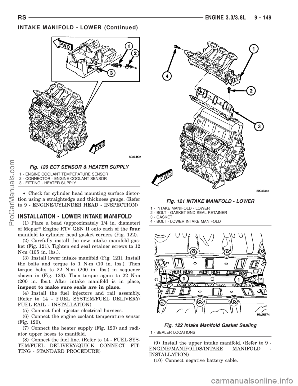
INSTALLATION - LOWER INTAKE MANIFOLD
(1) Place a bead (approximately 1/4 in. diameter)
of MopartEngine RTV GEN II onto each of thefour
manifold to cylinder head gasket corners (Fig. 122).
(2) Carefully install the new intake manifold gas-
ket (Fig. 121). Tighten end seal retainer screws to 12
N´m (105 in. lbs.).
(3) Install lower intake manifold (Fig. 121). Install
the bolts and torque to 1 N´m (10 in. lbs.). Then
torque bolts to 22 N´m (200 in. lbs.) in sequence
shown in (Fig. 123). Then torque again to 22 N´m
(200 in. lbs.). After intake manifold is in place,
inspect to make sure seals are in place.
(4) Install the fuel injectors and rail assembly.
(Refer to 14 - FUEL SYSTEM/FUEL DELIVERY/
FUEL RAIL - INSTALLATION)
(5) Connect fuel injector electrical harness.
(6) Connect the engine coolant temperature sensor
(Fig. 120).
(7) Connect the heater supply (Fig. 120) and radi-
ator upper hoses to manifold.
(8) Connect the fuel line. (Refer to 14 - FUEL SYS-
TEM/FUEL DELIVERY/QUICK CONNECT FIT-
TING - STANDARD PROCEDURE)(9) Install the upper intake manifold. (Refer to 9 -
ENGINE/MANIFOLDS/INTAKE MANIFOLD -
INSTALLATION)
(10) Connect negative battery cable.
Fig. 120 ECT SENSOR & HEATER SUPPLY
1 - ENGINE COOLANT TEMPERATURE SENSOR
2 - CONNECTOR - ENGINE COOLANT SENSOR
3 - FITTING - HEATER SUPPLY
Fig. 121 INTAKE MANIFOLD - LOWER
1 - INTAKE MANIFOLD - LOWER
2 - BOLT - GASKET END SEAL RETAINER
3 - GASKET
4 - BOLT - LOWER INTAKE MANIFOLD
Fig. 122 Intake Manifold Gasket Sealing
1 - SEALER LOCATIONS
RSENGINE 3.3/3.8L9 - 149
INTAKE MANIFOLD - LOWER (Continued)
ProCarManuals.com
Page 1377 of 2177
FUEL INJECTION
OPERATION
OPERATION - INJECTION SYSTEM
All engines used in this section have a sequential
Multi-Port Electronic Fuel Injection system. The MPI
system is computer regulated and provides precise
air/fuel ratios for all driving conditions. The Power-
train Control Module (PCM) operates the fuel injec-
tion system.
The PCM regulates:
²Ignition timing
²Air/fuel ratio
²Emission control devices
²Cooling fan
²Charging system
²Idle speed
²Vehicle speed control
Various sensors provide the inputs necessary for
the PCM to correctly operate these systems. In addi-
tion to the sensors, various switches also provide
inputs to the PCM.
The PCM can adapt its programming to meet
changing operating conditions.
Fuel is injected into the intake port above the
intake valve in precise metered amounts through
electrically operated injectors. The PCM fires the
injectors in a specific sequence. Under most operat-
ing conditions, the PCM maintains an air fuel ratio
of 14.7 parts air to 1 part fuel by constantly adjust-
ing injector pulse width. Injector pulse width is the
length of time the injector is open.
The PCM adjusts injector pulse width by opening
and closing the ground path to the injector. Engine
RPM (speed) and manifold absolute pressure (air
density) are theprimaryinputs that determine
injector pulse width.
OPERATION - MODES OF OPERATION
As input signals to the PCM change, the PCM
adjusts its response to output devices. For example,
the PCM must calculate a different injector pulse
width and ignition timing for idle than it does for
Wide Open Throttle (WOT). There are several differ-
ent modes of operation that determine how the PCM
responds to the various input signals.
There are two different areas of operation, OPEN
LOOP and CLOSED LOOP.
During OPEN LOOP modes the PCM receives
input signals and responds according to preset PCM
programming. Inputs from the upstream and down-
stream heated oxygen sensors are not monitored dur-
ing OPEN LOOP modes, except for heated oxygensensor diagnostics (they are checked for shorted con-
ditions at all times).
During CLOSED LOOP modes the PCM monitors
the inputs from the upstream and downstream
heated oxygen sensors. The upstream heated oxygen
sensor input tells the PCM if the calculated injector
pulse width resulted in the ideal air-fuel ratio of 14.7
to one. By monitoring the exhaust oxygen content
through the upstream heated oxygen sensor, the
PCM can fine tune injector pulse width. Fine tuning
injector pulse width allows the PCM to achieve opti-
mum fuel economy combined with low emissions.
For the PCM to enter CLOSED LOOP operation,
the following must occur:
(1) Engine coolant temperature must be over 35ÉF.
²If the coolant is over 35ÉF the PCM will wait 38
seconds.
²If the coolant is over 50ÉF the PCM will wait 15
seconds.
²If the coolant is over 167ÉF the PCM will wait 3
seconds.
(2) For other temperatures the PCM will interpo-
late the correct waiting time.
(3) O2 sensor must read either greater than 0.745
volts or less than 0.29 volt.
(4) The multi-port fuel injection systems has the
following modes of operation:
²Ignition switch ON (Zero RPM)
²Engine start-up
²Engine warm-up
²Cruise
²Idle
²Acceleration
²Deceleration
²Wide Open Throttle
²Ignition switch OFF
(5) The engine start-up (crank), engine warm-up,
deceleration with fuel shutoff and wide open throttle
modes are OPEN LOOP modes. Under most operat-
ing conditions, the acceleration, deceleration (with
A/C on), idle and cruise modes,with the engine at
operating temperatureare CLOSED LOOP modes.
IGNITION SWITCH ON (ZERO RPM) MODE
When the ignition switch activates the fuel injec-
tion system, the following actions occur:
²The PCM monitors the engine coolant tempera-
ture sensor and throttle position sensor input. The
PCM determines basic fuel injector pulse width from
this input.
²The PCM determines atmospheric air pressure
from the MAP sensor input to modify injector pulse
width.
When the key is in the ON position and the engine
is not running (zero rpm), the Auto Shutdown (ASD)
and fuel pump relays de-energize after approximately
14 - 18 FUEL INJECTIONRS
ProCarManuals.com
Page 1378 of 2177
1 second. Therefore, battery voltage is not supplied to
the fuel pump, ignition coil, fuel injectors and heated
oxygen sensors.
ENGINE START-UP MODE
This is an OPEN LOOP mode. If the vehicle is in
park or neutral (automatic transaxles) or the clutch
pedal is depressed (manual transaxles) the ignition
switch energizes the starter relay when the engine is
not running. The following actions occur when the
starter motor is engaged.
²If the PCM receives the camshaft position sensor
and crankshaft position sensor signals, it energizes
the Auto Shutdown (ASD) relay and fuel pump relay.
If the PCM does not receive both signals within
approximately one second, it will not energize the
ASD relay and fuel pump relay. The ASD and fuel
pump relays supply battery voltage to the fuel pump,
fuel injectors, ignition coil, (EGR solenoid and PCV
heater if equipped) and heated oxygen sensors.
²The PCM energizes the injectors (on the 69É
degree falling edge) for a calculated pulse width until
it determines crankshaft position from the camshaft
position sensor and crankshaft position sensor sig-
nals. The PCM determines crankshaft position within
1 engine revolution.
²After determining crankshaft position, the PCM
begins energizing the injectors in sequence. It adjusts
injector pulse width and controls injector synchroni-
zation by turning the individual ground paths to the
injectors On and Off.
²When the engine idles within 64 RPM of its
target RPM, the PCM compares current MAP sensor
value with the atmospheric pressure value received
during the Ignition Switch On (zero RPM) mode.
Once the ASD and fuel pump relays have been
energized, the PCM determines injector pulse width
based on the following:
²MAP
²Engine RPM
²Battery voltage
²Engine coolant temperature
²Inlet/Intake air temperature (IAT)
²Throttle position
²The number of engine revolutions since cranking
was initiated
During Start-up the PCM maintains ignition tim-
ing at 9É BTDC.
ENGINE WARM-UP MODE
This is an OPEN LOOP mode. The following inputs
are received by the PCM:
²Manifold Absolute Pressure (MAP)
²Crankshaft position (engine speed)
²Engine coolant temperature
²Inlet/Intake air temperature (IAT)²Camshaft position
²Knock sensor
²Throttle position
²A/C switch status
²Battery voltage
²Vehicle speed
²Speed control
²O2 sensors
The PCM adjusts injector pulse width and controls
injector synchronization by turning the individual
ground paths to the injectors On and Off.
The PCM adjusts ignition timing and engine idle
speed. Engine idle speed is adjusted through the idle
air control motor.
CRUISE OR IDLE MODE
When the engine is at operating temperature this
is a CLOSED LOOP mode. During cruising or idle
the following inputs are received by the PCM:
²Manifold absolute pressure
²Crankshaft position (engine speed)
²Inlet/Intake air temperature
²Engine coolant temperature
²Camshaft position
²Knock sensor
²Throttle position
²Exhaust gas oxygen content (O2 sensors)
²A/C switch status
²Battery voltage
²Vehicle speed
The PCM adjusts injector pulse width and controls
injector synchronization by turning the individual
ground paths to the injectors On and Off.
The PCM adjusts engine idle speed and ignition
timing. The PCM adjusts the air/fuel ratio according
to the oxygen content in the exhaust gas (measured
by the upstream and downstream heated oxygen sen-
sor).
The PCM monitors for engine misfire. During
active misfire and depending on the severity, the
PCM either continuously illuminates or flashes the
malfunction indicator lamp (Check Engine light on
instrument panel). Also, the PCM stores an engine
misfire DTC in memory, if 2nd trip with fault.
The PCM performs several diagnostic routines.
They include:
²Oxygen sensor monitor
²Downstream heated oxygen sensor diagnostics
during open loop operation (except for shorted)
²Fuel system monitor
²EGR monitor (if equipped)
²Purge system monitor
²Catalyst efficiency monitor
²All inputs monitored for proper voltage range,
rationality.
RSFUEL INJECTION14-19
FUEL INJECTION (Continued)
ProCarManuals.com
Page 1379 of 2177
²All monitored components (refer to the Emission
section for On-Board Diagnostics).
The PCM compares the upstream and downstream
heated oxygen sensor inputs to measure catalytic
convertor efficiency. If the catalyst efficiency drops
below the minimum acceptable percentage, the PCM
stores a diagnostic trouble code in memory, after 2
trips.
During certain idle conditions, the PCM may enter
a variable idle speed strategy. During variable idle
speed strategy the PCM adjusts engine speed based
on the following inputs.
²A/C status
²Battery voltage
²Battery temperature or Calculated Battery Tem-
perature
²Engine coolant temperature
²Engine run time
²Inlet/Intake air temperature
²Vehicle mileage
ACCELERATION MODE
This is a CLOSED LOOP mode. The PCM recog-
nizes an abrupt increase in Throttle Position sensor
output voltage or MAP sensor output voltage as a
demand for increased engine output and vehicle
acceleration. The PCM increases injector pulse width
in response to increased fuel demand.
²Wide Open Throttle-open loop
DECELERATION MODE
This is a CLOSED LOOP mode. During decelera-
tion the following inputs are received by the PCM:
²A/C status
²Battery voltage
²Inlet/Intake air temperature
²Engine coolant temperature
²Crankshaft position (engine speed)
²Exhaust gas oxygen content (upstream heated
oxygen sensor)
²Knock sensor
²Manifold absolute pressure
²Throttle position sensor
²IAC motor (solenoid) control changes in response
to MAP sensor feedback
The PCM may receive a closed throttle input from
the Throttle Position Sensor (TPS) when it senses an
abrupt decrease in manifold pressure. This indicates
a hard deceleration (Open Loop). In response, the
PCM may momentarily turn off the injectors. This
helps improve fuel economy, emissions and engine
braking.
WIDE-OPEN-THROTTLE MODE
This is an OPEN LOOP mode. During wide-open-
throttle operation, the following inputs are used by
the PCM:
²Inlet/Intake air temperature
²Engine coolant temperature
²Engine speed
²Knock sensor
²Manifold absolute pressure
²Throttle position
When the PCM senses a wide-open-throttle condi-
tion through the Throttle Position Sensor (TPS) it de-
energizes the A/C compressor clutch relay. This
disables the air conditioning system and disables
EGR (if equipped).
The PCM adjusts injector pulse width to supply a
predetermined amount of additional fuel, based on
MAP and RPM.
IGNITION SWITCH OFF MODE
When the operator turns the ignition switch to the
OFF position, the following occurs:
²All outputs are turned off, unless 02 Heater
Monitor test is being run. Refer to the Emission sec-
tion for On-Board Diagnostics.
²No inputs are monitored except for the heated
oxygen sensors. The PCM monitors the heating ele-
ments in the oxygen sensors and then shuts down.
FUEL CORRECTION or ADAPTIVE MEMORIES
DESCRIPTION
In Open Loop, the PCM changes pulse width with-
out feedback from the O2 Sensors. Once the engine
warms up to approximately 30 to 35É F, the PCM
goes into closed loopShort Term Correctionand
utilizes feedback from the O2 Sensors. Closed loop
Long Term Adaptive Memoryis maintained above
170É to 190É F unless the PCM senses wide open
throttle. At that time the PCM returns to Open Loop
operation.
OPERATION
Short Term
The first fuel correction program that begins func-
tioning is the short term fuel correction. This system
corrects fuel delivery in direct proportion to the read-
ings from the Upstream O2 Sensor.
The PCM monitors the air/fuel ratio by using the
input voltage from the O2 Sensor. When the voltage
reaches its preset high or low limit, the PCM begins
to add or remove fuel until the sensor reaches its
switch point. The short term corrections then begin.
The PCM makes a series of quick changes in the
injector pulse-width until the O2 Sensor reaches its
14 - 20 FUEL INJECTIONRS
FUEL INJECTION (Continued)
ProCarManuals.com
Page 1387 of 2177
(2) Install injector clip by sliding open end into the
top slot of the injector. The edge of the receiver cup
will slide into the side slots of clip (Fig. 13).
(3) Install injector top end into fuel rail receiver
cap. Be careful not to damage O-ring during installa-
tion (Fig. 13).
(4) Repeat steps for remaining injectors.
(5) Install fuel rail, refer to Fuel Rail in the Fuel
Delivery section.
(6) Connect fuel injector wiring.
(7) Install the Intake Manifold, (Refer to 9 -
ENGINE/MANIFOLDS/INTAKE MANIFOLD -
INSTALLATION)
(8) Connect the negative battery cable.
FUEL PUMP RELAY
DESCRIPTION
The fuel pump relay is located in the PDC. The
inside top of the PDC cover has a label showing relay
and fuse location.
OPERATION
The fuel pump relay supplies battery voltage to the
fuel pump. A buss bar in the Power Distribution Cen-
ter (PDC) supplies voltage to the solenoid side and
contact side of the relay. The fuel pump relay power
circuit contains a fuse between the buss bar in the
PDC and the relay. The fuse is located in the PDC.
Refer to the Wiring Diagrams for circuit information.
The PCM controls the fuel pump relay by switch-
ing the ground path for the solenoid side of the relay
on and off. The PCM turns the ground path off when
the ignition switch is in the Off position. When the
ignition switch is in the On position, the PCM ener-
gizes the fuel pump. If the crankshaft position sensor
does not detect engine rotation, the PCM de-ener-
gizes the relay after approximately one second.
IDLE AIR CONTROL MOTOR
DESCRIPTION
The idle air control motor is mounted on the throt-
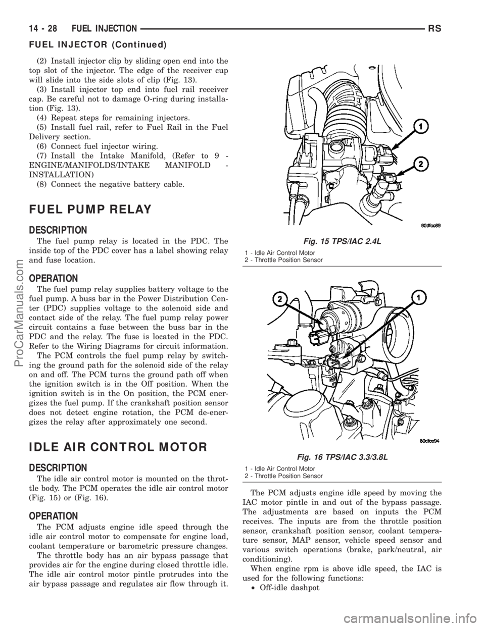
tle body. The PCM operates the idle air control motor
(Fig. 15) or (Fig. 16).
OPERATION
The PCM adjusts engine idle speed through the
idle air control motor to compensate for engine load,
coolant temperature or barometric pressure changes.
The throttle body has an air bypass passage that
provides air for the engine during closed throttle idle.
The idle air control motor pintle protrudes into the
air bypass passage and regulates air flow through it.The PCM adjusts engine idle speed by moving the
IAC motor pintle in and out of the bypass passage.
The adjustments are based on inputs the PCM
receives. The inputs are from the throttle position
sensor, crankshaft position sensor, coolant tempera-
ture sensor, MAP sensor, vehicle speed sensor and
various switch operations (brake, park/neutral, air
conditioning).
When engine rpm is above idle speed, the IAC is
used for the following functions:
²Off-idle dashpot
Fig. 15 TPS/IAC 2.4L
1 - Idle Air Control Motor
2 - Throttle Position Sensor
Fig. 16 TPS/IAC 3.3/3.8L
1 - Idle Air Control Motor
2 - Throttle Position Sensor
14 - 28 FUEL INJECTIONRS
FUEL INJECTOR (Continued)
ProCarManuals.com
Page 1480 of 2177

REMOVAL - 2.5L TD
(1) Raise hood.
(2) Disconnect both battery cables.
(3) Remove battery thermal shield (Fig. 15).
(4) Remove battery hold down bolt, clamp, and
battery (Fig. 16).(5) Remove battery tray (Fig. 17). Disconnect bat-
tery temperature sensor.
(6) Remove coolant recovery bottle from bracket.
(7) Remove coolant recovery bottle mounting
bracket (Fig. 18).
(8) Disconnect gearshift cables from shift levers/
cover assembly (Fig. 19).
(9) Remove gearshift cable retaining clips from
mounting bracket (Fig. 19). Remove cables and
secure out of way.
Fig. 15 Battery Thermal Shield
1 - BATTERY THERMAL SHIELD
Fig. 16 Battery and Hold-Down Clamp
1 - BATTERY
2 - HOLD-DOWN CLAMP
Fig. 17 Battery Tray
1 - BATTERY TRAY
Fig. 18 Coolant Recovery Bottle Bracket
1 - COOLANT RECOVERY BOTTLE BRACKET
2 - NUT
3 - MOUNT BRACKET
RST850 MANUAL TRANSAXLE21-33
T850 MANUAL TRANSAXLE (Continued)
ProCarManuals.com
Page 1499 of 2177

(13) Install right mount bracket to transaxle (Fig.
80).
(14) Connect gearshift cables to shift levers/cover
assembly (Fig. 81). Install cables into position at
mount bracket and secure with retaining clips.
(15) Connect battery cables.
(16) Check transaxle fluid and engine coolant lev-
els. Adjust if necessary. (Refer to 21 - TRANSMIS-
SION/TRANSAXLE/MANUAL/FLUID - STANDARD
PROCEDURE)
INSTALLATION - 2.5L TD
(1) Assemble transaxle to engine, while aligning
transaxle input shaft to clutch disc splines.
(2) Install and torque transaxle-to-engine bolts to
95 N´m (70 ft. lbs.) (Fig. 82).
(3) Install transaxle upper mount (Fig. 83). Install
and torque four (4) mount-to-transaxle bolts to 54
N´m (40 ft. lbs.).
(4) Raise transaxle/engine assembly into position
and install upper mount through-bolt. Torque
through-bolt to 75 N´m (55 ft. lbs.).
(5) Remove screw jack.
(6) Connect back-up lamp switch connector.
(7) Install starter motor into position (Fig. 84).
Install and torque bolts to 54 N´m (40 ft. lbs.).
Fig. 80 Transaxle Right Mount and Bracket
1 - MOUNT BRACKET
2 - BOLT (3)
3 - MOUNT
4 - BOLT (1)
Fig. 81 Gearshift Cables at Transaxle
1 - SELECTOR CABLE
2 - CABLE RETAINER
3 - CABLE RETAINER
4 - CROSSOVER CABLE
5 - MOUNT BRACKET
21 - 52 T850 MANUAL TRANSAXLERS
T850 MANUAL TRANSAXLE (Continued)
ProCarManuals.com
Page 1502 of 2177

(15) Install coolant recovery bottle bracket (Fig.
88).
(16) Install coolant recovery bottle to bracket.
(17) Connect battery temperature sensor and
install battery tray (Fig. 89).(18) Install battery, hold-down clamp and nut (Fig.
90).
(19) Install battery thermal shield and clutch cable
eyelet (Fig. 91).
(20) Connect battery cables.
(21) Check transaxle fluid and engine coolant lev-
els. Adjust if necessary. (Refer to 21 - TRANSMIS-
SION/TRANSAXLE/MANUAL/FLUID - STANDARD
PROCEDURE)
Fig. 88 Coolant Recovery Bottle Bracket
1 - COOLANT RECOVERY BOTTLE BRACKET
2 - NUT
3 - MOUNT BRACKET
Fig. 89 Battery Tray
1 - BATTERY TRAY
Fig. 90 Battery and Hold-Down Clamp
1 - BATTERY
2 - HOLD-DOWN CLAMP
Fig. 91 Battery Thermal Shield
1 - BATTERY THERMAL SHIELD
RST850 MANUAL TRANSAXLE21-55
T850 MANUAL TRANSAXLE (Continued)
ProCarManuals.com