bulb CHRYSLER CARAVAN 2003 Service Manual
[x] Cancel search | Manufacturer: CHRYSLER, Model Year: 2003, Model line: CARAVAN, Model: CHRYSLER CARAVAN 2003Pages: 2177, PDF Size: 59.81 MB
Page 330 of 2177
OPERATION - SENSOR RETURN - PCM INPUT
The sensor return circuit provides a low electrical
noise ground reference for all of the systems sensors.
The sensor return circuit connects to internal ground
circuits within the Powertrain Control Module
(PCM).
OPERATION - DATA BUS COMMUNICATION
RECEIVE - PCM INPUT
The PCM uses the SCI communication bus to pre-
form engine diagnostics and flash operations. The
transmission side of the PCM uses the SCI commu-
nication bus to flash new software. However, diagnos-
tics is performed via the vehicles J1850 bus for the
transmission side of the PCM.
OPERATION - IGNITION SENSE - PCM INPUT
The ignition sense input informs the Powertrain
Control Module (PCM) that the ignition switch is in
the crank or run position.
OPERATION - PCM GROUND
Ground is provided through multiple pins of the
PCM connector. Depending on the vehicle there may
be as many as two different ground pins. There are
power grounds and sensor grounds.
The power grounds are used to control the ground
side relays, solenoids, ignition coil or injectors. The
signal ground is used for any input that uses sensor
return for ground, and the ground side of any inter-
nal processing component.
The PCM case is shielded to prevent RFI and EMI.
The PCM case is grounded and must be firmly
attached to a good, clean body ground.
Internally all grounds are connected together, how-
ever there is noise suppression on the sensor ground.
For EMI and RFI protection the housing and cover
are also grounded separately from the ground pins.
OPERATION
OPERATION - 8-VOLT SUPPLY - PCM OUTPUT
- SBEC CONTROLLER
The PCM supplies 8 volts to the crankshaft posi-
tion sensor, camshaft position sensor.
OPERATION - 5 VOLT SUPPLY - PCM OUTPUT
The PCM supplies 5 volts to the following sensors:
²A/C pressure transducer
²Ambient Temperature sensor
²Battery temperature
²Camshaft Position Sensor (NGC)
²Crankshaft Position Sensor (NGC)
²Electronic Throttle Control (1.6L)²Engine coolant temperature sensor
²Inlet Air Temperature Sensor
²Knock sensor
²Linear EGR solenoid (if equipped)
²Manifold absolute pressure sensor
²Oil Pressure Switch
²Pedal Position Sensor (1.6L)
²Throttle position sensor
²Vehicle Speed Sensor
STANDARD PROCEDURE
STANDARD PROCEDURE - OBTAINING
DIAGNOSTIC TROUBLE CODES
BULB CHECK
Key on: Bulb illuminated until vehicle starts, as
long as all once per trip (readiness) monitors com-
pleted. If monitors havenotbeen completed, then:
Key on: bulb check for about 5 to 8 seconds, lamp
then flashes if once per trip (readiness) monitors
havenotbeen completed until vehicle is started,
then MIL is extinguished.
OBTAINING DTC'S USING DRB SCAN TOOL
(1) Connect the DRB scan tool to the data link
(diagnostic) connector. This connector is located in
the passenger compartment; at the lower edge of
instrument panel; near the steering column.
(2) Turn the ignition switch on and access the
ªRead Faultº screen.
(3) Record all the DTC's and ªfreeze frameº infor-
mation shown on the DRB scan tool.
(4) To erase DTC's, use the ªErase Trouble Codeº
data screen on the DRB scan tool.Do not erase any
DTC's until problems have been investigated
and repairs have been performed.
STANDARD PROCEDURE - PINION FACTOR
SETTING
NOTE: This procedure must be performed if the
PCM/TCM has been replaced with a NEW or
replacement unit. Failure to perform this procedure
will result in an inoperative or improperly calibrated
speedometer.
The vehicle speed readings for the speedometer are
taken from the output speed sensor. The PCM/TCM
must be calibrated to the different combinations of
equipment (final drive and tires) available. Pinion
Factor allows the technician to set the Powertrain/
Transmission Control Module initial setting so that
the speedometer readings will be correct. To properly
RSELECTRONIC CONTROL MODULES8E-15
POWERTRAIN CONTROL MODULE (Continued)
ProCarManuals.com
Page 406 of 2177
INSTRUMENT CLUSTER
TABLE OF CONTENTS
page page
INSTRUMENT CLUSTER
DESCRIPTION..........................1
OPERATION............................1
DIAGNOSIS AND TESTING
DIAGNOSIS AND TESTING - SELF-
DIAGNOSTICS.........................2
DIAGNOSIS AND TESTING - CLUSTER
DIAGNOSIS...........................2REMOVAL.............................10
INSTALLATION.........................10
CLUSTER LENS
REMOVAL.............................10
INSTALLATION.........................10
INSTRUMENT CLUSTER
DESCRIPTION
The instrumentation gauges are contained in a
subdial assembly within the instrument cluster. The
individual gauges are not serviceable. If one of the
cluster gauges becomes faulty, the entire cluster
would require replacement.
The Mechanical Instrument Cluster (MIC) with a
tachometer is equipped with a electronic vacuum flu-
orescent transmission range indicator (PRND3L),
odometer, and trip odometer display.
The MIC without a tachometer is equipped with a
Light Emitting Diode (LED) transmission range indi-
cator (PRND3L) and a vacuum fluorescent odometer
display.
The MIC is equipped with the following warning
lamps.
²Lift Gate Ajar
²Low Fuel Level
²Low Windshield Washer Fluid Level
²Cruise
²Battery Voltage
²Fasten Seat Belt
²Door Ajar
²Coolant Temperature
²Anti-Lock Brake
²Brake
²Oil Pressure
²MIL (Malfunction Indicator Lamp)
²VTSS/SKIS Indicator
²Airbag
²Traction Control
²Autostick
The MIC without a tachometer also has the follow-
ing warning lamps:
²Turns Signals
²High Beam
WATER IN FUEL LAMP - EXPORT
The Water In Fuel Lamp is located in the message
center. When moisture is found within the fuel sys-
tem, the sensor sends a message via the PCI data
bus to the instrument cluster. The MIC illuminates
the bulb in the message center, The sensor is located
underneath the vehicle, directly above the rear axle.
The sensor is housed within the fuel filter/water sep-
arator assembly cover. The sensor is not serviced sep-
arately. If found defective, the entire assembly cover
must be replaced.
OPERATION
Refer to the vehicle Owner's Manual for operation
instructions and conditions for the Instrument Clus-
ter Gauges.
WATER IN FUEL LAMP - EXPORT
The Water In Fuel Sensor is a resistive type
switch. It is calibrated to sense the different resis-
tance between diesel fuel and water. When water
enters the fuel system, it is caught in the bottom of
the fuel filter/water separator assembly, where the
sensor is located. Water has less resistance than die-
sel fuel. The sensor then sends a PCI data bus mes-
sage to the instrument cluster to illuminate the
lamp.
If the lamp is inoperative, perform the self diag-
nostic test on the instrument cluster to check the
lamp operation before continuing diagnosis.
RSINSTRUMENT CLUSTER8J-1
ProCarManuals.com
Page 407 of 2177
DIAGNOSIS AND TESTING
DIAGNOSIS AND TESTING - SELF-DIAGNOSTICS
The instrument clusters are equipped with a self
diagnostic test feature to help identify electronic prob-
lems. Prior to any test, perform the Self-Diagnostic
Test. The self diagnostic system displays instrument
cluster stored fault codes in the odometer display,
sweeps the gauges to the calibration points, and bulb
checks the warning indicators. When the key is in the
ON position with the engine not running, the MIL will
remain illuminated for regulatory purposes.
To activate the Self-Diagnostic program:
(1) With the ignition switch in the OFF position,
depress the TRIP ODOMETER RESET button.
(2) Continue to hold the TRIP ODOMETER
RESET button untilSofand a number (software ver-
sion number (i.e.Sof 3.2) appears in the odometer
window then release the button. If a fault code is
present, the cluster will display it in the odometer
display. When all fault codes have been displayed,
the cluster will displayªendºin the odometer dis-
play. Refer to the INSTRUMENT CLUSTER DTC'S
table to determine what each trouble code means.
INSTRUMENT CLUSTER DTC'S
DTC DESCRIPTION
100.0 LOOP-BACK FAILURE
100.1 ABS COMMUNICATION FAULT
100.2 BCM COMMUNICATION FAULT
100.3 EATX COMMUNICATION FAULT
100.4 FCM COMMUNICATION FAULT
100.5 ORC COMMUNICATION FAULT
100.6SBEC/DEC/MCM COMMUNICATION
FAULT
200.0 AIRBAG LED SHORT
200.1 AIRBAG LED OPEN
200.2 ABS LED SHORT
200.3 ABS LED OPEN
200.6 EL INVERTER TIME-OUT
200.7 EATX MISMATCH
400.0 EEPROM READ/WRITE FAILURE
400.1IMPROPER POWER DOWN
DETECTED
CALIBRATION TEST
The CLUSTER CALIBRATION table contains the
proper calibration points for each gauge. If the gauge
pointers are not calibrated, a problem exists in the
cluster. If any gauge is out of calibration, replace the
cluster.
CLUSTER CALIBRATION
SPEEDOMETER CALIBRATION POINT
1 0 MPH (0 KM/H)
2 20 MPH (40 KM/H)
3 60 MPH (100 KM/H)
4 100 MPH (160 KM/H)
TACHOMETER
1 0 RPM
2 1000 RPM
3 3000 RPM
4 6000 RPM
FUEL GAUGE
1 EMPTY
2 1/4 FILLED
3 1/2 FILLED
4 FULL
TEMPERATURE
GAUGE
1 COLD
2 1/4
3 3/4
4 HOT
ODOMETER SEGMENT TEST
If a segment in the odometer does not illuminate
normally, a problem exists in the display.
ELECTRONIC TRANSMISSION RANGE INDICATOR
SEGMENT TEST
If a segment in the transmission range indicator
does not illuminate normally, a problem exists in the
display.
DIAGNOSIS AND TESTING - CLUSTER
DIAGNOSIS
CONDITIONS
Refer to the following tables for possible problems,
causes, and corrections.
²INSTRUMENT CLUSTER DIAGNOSIS
²SPEEDOMETER DIAGNOSIS
²TACHOMETER DIAGNOSIS
²FUEL GAUGE DIAGNOSIS
²TEMPERATURE GAUGE DIAGNOSIS
²ODOMETER DIAGNOSIS
²ELECTRONIC GEAR INDICATOR DISPLAY
DIAGNOSIS
NOTE: Always check the functionality of the cluster
by running the self test prior to troubleshooting.
8J - 2 INSTRUMENT CLUSTERRS
INSTRUMENT CLUSTER (Continued)
ProCarManuals.com
Page 417 of 2177
MULTI-FUNCTION SWITCH
DESCRIPTION - TURN SIGNAL SYSTEM.....21
OPERATION - TURN SIGNAL SYSTEM.......21
DIAGNOSIS AND TESTING - MULTI-
FUNCTION SWITCH...................21
REMOVAL.............................21
INSTALLATION.........................21
PARK/TURN SIGNAL LAMP
REMOVAL.............................21
INSTALLATION.........................21
PARK/TURN SIGNAL LAMP - EXPORT
REMOVAL.............................22
INSTALLATION.........................22
REAR FOG LAMP - EXPORT
DESCRIPTION.........................22REPEATER LAMP - EXPORT
REMOVAL.............................22
INSTALLATION.........................22
TAIL LAMP
REMOVAL.............................22
INSTALLATION.........................22
TAIL LAMP - EXPORT
REMOVAL.............................23
INSTALLATION.........................23
TAIL LAMP UNIT
REMOVAL.............................23
INSTALLATION.........................23
LAMPS/LIGHTING - EXTERIOR
DESCRIPTION
LAMP SYSTEMS
Lighting circuits are protected by fuses. Lighting
circuits require an overload protected power and high
side drivers source, ON/OFF device, lamps and body
grounds to operate properly. Plastic lamps require a
wire in the harness to supply body ground to the
lamp socket. Replace sockets and bulbs that are cor-
roded.
Some of the interior and exterior lighting functions
are governed by the Body Control Module (BCM).
The headlamp, dome, and the door ajar switches pro-
vide signals to the BCM. The BCM in turn sends a
Programmable Communication Interface (PCI) bus
message to the Front Control Module (FCM) to
enable the necessary drivers to set the required illu-
mination configuration.
Wire connectors can make intermittent contact or
become corroded. Before coupling wire connectors,
inspect the terminals inside the connector. Male ter-
minals should not be bent or disengaged from the
insulator. Female terminals should not be sprung
open or disengaged from the insulator. Bent and
sprung terminals can be repaired using needle nose
pliers and pick tool. Corroded terminals appear
chalky or green. Corroded terminals should be
replaced to avoid recurrence of the problem symp-
toms.
Begin electrical system failure diagnosis by testing
related fuses in the fuse block and intelligent power
module. Verify that bulbs are in good condition and
test continuity of the circuit ground. Refer to the
appropriate wiring information.
AUTOMATIC HEADLAMP SYSTEM
The Automatic Headlamp system turns the instru-
mentation and exterior illumination lamps ON when
the ambient light levels are Night and the engine
RPM is 450 or above, and OFF when light levels are
Day.
DAYTIME RUNNING LAMPS
Operating the high-beam headlamps at reduced
power provides daytime running lamps, which are
required on all new Canadian vehicles.
HEADLAMPS ON WITH WINDSHIELD WIPERS
For vehicles equipped with the Automatic Head-
lamp System, the instrumentation and exterior illu-
mination lamps will be turned ON when the
headlamp switch is in the AUTO position, RPM >
450 and the windshield wipers have been in the
intermittent, low or high mode of operation for more
than ten seconds. When the windshield wipers are
turned OFF the Body Control Module will determine
if the instrumentation and exterior illumination
lamps should remain ON base upon the current
ambient light level.
HEADLAMP SYSTEM
The configuration of the headlamp system of head-
lamps, park lamps and fog lamps is determined by
the BCM. The BCM determines the lighting configu-
ration as a result of the inputs from the ignition
switch, headlamp switch and multi-function switch. A
PCI bus is transmitted from the BCM to the FCM to
enable the necessary drivers to set the illumination
configuration. Four wires are connected between the
headlamp switch and the BCM. The first wire con-
tains information regarding the position of the head-
lamp switch (Off, Automatic Headlamps, Automatic
Headlamp switch fog, Park with Fog, Head, or Head
with Fog Lamps). The second wire contains informa-
tion regarding the position of the dimmer switch
8L - 2 LAMPS/LIGHTING - EXTERIORRS
ProCarManuals.com
Page 419 of 2177
WARNING
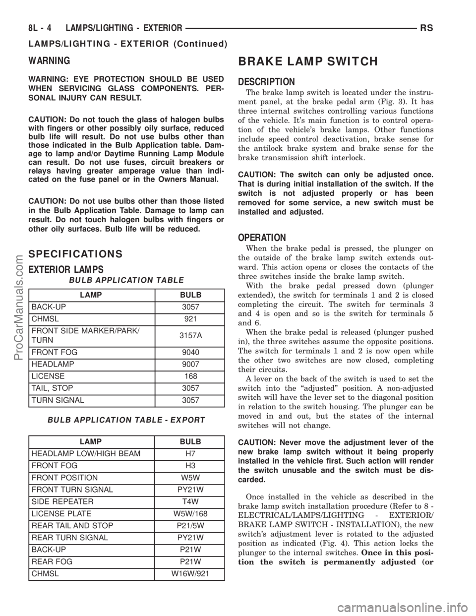
WARNING: EYE PROTECTION SHOULD BE USED
WHEN SERVICING GLASS COMPONENTS. PER-
SONAL INJURY CAN RESULT.
CAUTION: Do not touch the glass of halogen bulbs
with fingers or other possibly oily surface, reduced
bulb life will result. Do not use bulbs other than
those indicated in the Bulb Application table. Dam-
age to lamp and/or Daytime Running Lamp Module
can result. Do not use fuses, circuit breakers or
relays having greater amperage value than indi-
cated on the fuse panel or in the Owners Manual.
CAUTION: Do not use bulbs other than those listed
in the Bulb Application Table. Damage to lamp can
result. Do not touch halogen bulbs with fingers or
other oily surfaces. Bulb life will be reduced.
SPECIFICATIONS
EXTERIOR LAMPS
BULB APPLICATION TABLE
LAMP BULB
BACK-UP 3057
CHMSL 921
FRONT SIDE MARKER/PARK/
TURN3157A
FRONT FOG 9040
HEADLAMP 9007
LICENSE 168
TAIL, STOP 3057
TURN SIGNAL 3057
BULB APPLICATION TABLE - EXPORT
LAMP BULB
HEADLAMP LOW/HIGH BEAM H7
FRONT FOG H3
FRONT POSITION W5W
FRONT TURN SIGNAL PY21W
SIDE REPEATER T4W
LICENSE PLATE W5W/168
REAR TAIL AND STOP P21/5W
REAR TURN SIGNAL PY21W
BACK-UP P21W
REAR FOG P21W
CHMSL W16W/921
BRAKE LAMP SWITCH
DESCRIPTION
The brake lamp switch is located under the instru-
ment panel, at the brake pedal arm (Fig. 3). It has
three internal switches controlling various functions
of the vehicle. It's main function is to control opera-
tion of the vehicle's brake lamps. Other functions
include speed control deactivation, brake sense for
the antilock brake system and brake sense for the
brake transmission shift interlock.
CAUTION: The switch can only be adjusted once.
That is during initial installation of the switch. If the
switch is not adjusted properly or has been
removed for some service, a new switch must be
installed and adjusted.
OPERATION
When the brake pedal is pressed, the plunger on
the outside of the brake lamp switch extends out-
ward. This action opens or closes the contacts of the
three switches inside the brake lamp switch.
With the brake pedal pressed down (plunger
extended), the switch for terminals 1 and 2 is closed
completing the circuit. The switch for terminals 3
and 4 is open and so is the switch for terminals 5
and 6.
When the brake pedal is released (plunger pushed
in), the three switches assume the opposite positions.
The switch for terminals 1 and 2 is now open while
the other two switches are now closed, completing
their circuits.
A lever on the back of the switch is used to set the
switch into the ªadjustedº position. A non-adjusted
switch will have the lever set to the diagonal position
in relation to the switch housing. The plunger can be
moved in and out, but the states of the internal
switches will not change.
CAUTION: Never move the adjustment lever of the
new brake lamp switch without it being properly
installed in the vehicle first. Such action will render
the switch unusable and the switch must be dis-
carded.
Once installed in the vehicle as described in the
brake lamp switch installation procedure (Refer to 8 -
ELECTRICAL/LAMPS/LIGHTING - EXTERIOR/
BRAKE LAMP SWITCH - INSTALLATION), the new
switch's adjustment lever is rotated to the adjusted
position as indicated (Fig. 4). This action locks the
plunger to the internal switches.Once in this posi-
tion the switch is permanently adjusted (or
8L - 4 LAMPS/LIGHTING - EXTERIORRS
LAMPS/LIGHTING - EXTERIOR (Continued)
ProCarManuals.com
Page 421 of 2177

(b) Install the switch in its bracket by aligning
the index tab on the switch with the slot in the
mounting bracket.
(c) When the switch is fully seated in its
bracket, rotate the switch clockwise approximately
30É to lock the switch into place.
(d) With the brake pedal in the fully released
position, move the lever on the back of the brake
lamp switch from the angled non-adjusted position
to the full vertical position as shown (Fig. 4). This
will adjust the brake lamp switch to the vehicle.(2) Install silencer panel below steering column
knee blocker.
(3) Reconnect the battery negative terminal.
(4) Check the stop lamps to verify they are operat-
ing properly and not staying on when the pedal is in
the released position.
(5) Road test the vehicle to ensure proper opera-
tion of the brakes including ABS and speed control (if
equipped).
CENTER HIGH MOUNTED
STOP LAMP
REMOVAL
(1) Disconnect and isolate the battery negative
cable.
(2) Remove two retaining screws (Fig. 5).
(3) Twist socket counter-clockwise and remove
from lamp.
(4) Pull bulb from socket (Fig. 7).
INSTALLATION
(1) Push bulb into socket.
(2) Install socket into the lamp unit.
(3) Install the retaining screws.
(4) Reconnect the battery negative cable.
CENTER HIGH MOUNTED
STOP LAMP UNIT
REMOVAL
(1) Disconnect and isolate the battery negative
cable.
(2) Remove the two retaining screws (Fig. 5).
(3) Disconnect the rear window washer nozzle
assembly (Fig. 6).
Fig. 3 Brake Lamp Switch And Pedal With Bracket
1 - BRAKE LAMP SWITCH
2 - WIRING CONNECTOR
3 - PEDAL AND BRACKET
Fig. 4 Adjustment Lever Movement
Fig. 5 CHMSL UNIT
1 - CHMSL UNIT
2 - LIFTGATE
8L - 6 LAMPS/LIGHTING - EXTERIORRS
BRAKE LAMP SWITCH (Continued)
ProCarManuals.com
Page 422 of 2177
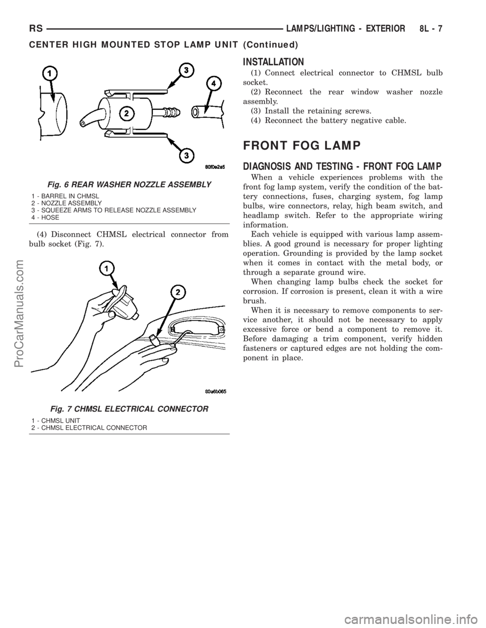
(4) Disconnect CHMSL electrical connector from
bulb socket (Fig. 7).
INSTALLATION
(1) Connect electrical connector to CHMSL bulb
socket.
(2) Reconnect the rear window washer nozzle
assembly.
(3) Install the retaining screws.
(4) Reconnect the battery negative cable.
FRONT FOG LAMP
DIAGNOSIS AND TESTING - FRONT FOG LAMP
When a vehicle experiences problems with the
front fog lamp system, verify the condition of the bat-
tery connections, fuses, charging system, fog lamp
bulbs, wire connectors, relay, high beam switch, and
headlamp switch. Refer to the appropriate wiring
information.
Each vehicle is equipped with various lamp assem-
blies. A good ground is necessary for proper lighting
operation. Grounding is provided by the lamp socket
when it comes in contact with the metal body, or
through a separate ground wire.
When changing lamp bulbs check the socket for
corrosion. If corrosion is present, clean it with a wire
brush.
When it is necessary to remove components to ser-
vice another, it should not be necessary to apply
excessive force or bend a component to remove it.
Before damaging a trim component, verify hidden
fasteners or captured edges are not holding the com-
ponent in place.Fig. 6 REAR WASHER NOZZLE ASSEMBLY
1 - BARREL IN CHMSL
2 - NOZZLE ASSEMBLY
3 - SQUEEZE ARMS TO RELEASE NOZZLE ASSEMBLY
4 - HOSE
Fig. 7 CHMSL ELECTRICAL CONNECTOR
1 - CHMSL UNIT
2 - CHMSL ELECTRICAL CONNECTOR
RSLAMPS/LIGHTING - EXTERIOR8L-7
CENTER HIGH MOUNTED STOP LAMP UNIT (Continued)
ProCarManuals.com
Page 423 of 2177
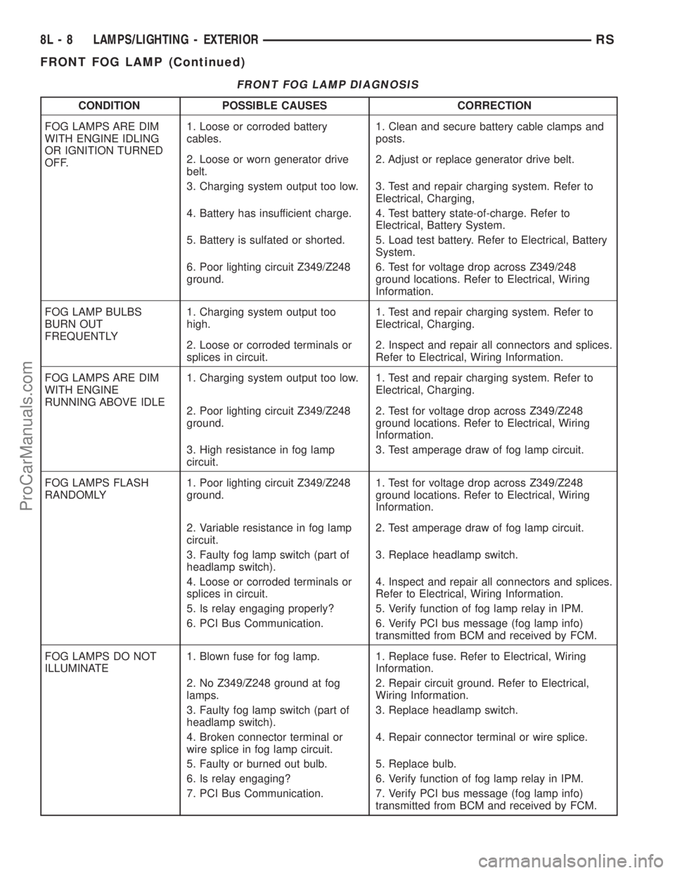
FRONT FOG LAMP DIAGNOSIS
CONDITION POSSIBLE CAUSES CORRECTION
FOG LAMPS ARE DIM
WITH ENGINE IDLING
OR IGNITION TURNED
OFF.1. Loose or corroded battery
cables.1. Clean and secure battery cable clamps and
posts.
2. Loose or worn generator drive
belt.2. Adjust or replace generator drive belt.
3. Charging system output too low. 3. Test and repair charging system. Refer to
Electrical, Charging,
4. Battery has insufficient charge. 4. Test battery state-of-charge. Refer to
Electrical, Battery System.
5. Battery is sulfated or shorted. 5. Load test battery. Refer to Electrical, Battery
System.
6. Poor lighting circuit Z349/Z248
ground.6. Test for voltage drop across Z349/248
ground locations. Refer to Electrical, Wiring
Information.
FOG LAMP BULBS
BURN OUT
FREQUENTLY1. Charging system output too
high.1. Test and repair charging system. Refer to
Electrical, Charging.
2. Loose or corroded terminals or
splices in circuit.2. Inspect and repair all connectors and splices.
Refer to Electrical, Wiring Information.
FOG LAMPS ARE DIM
WITH ENGINE
RUNNING ABOVE IDLE1. Charging system output too low. 1. Test and repair charging system. Refer to
Electrical, Charging.
2. Poor lighting circuit Z349/Z248
ground.2. Test for voltage drop across Z349/Z248
ground locations. Refer to Electrical, Wiring
Information.
3. High resistance in fog lamp
circuit.3. Test amperage draw of fog lamp circuit.
FOG LAMPS FLASH
RANDOMLY1. Poor lighting circuit Z349/Z248
ground.1. Test for voltage drop across Z349/Z248
ground locations. Refer to Electrical, Wiring
Information.
2. Variable resistance in fog lamp
circuit.2. Test amperage draw of fog lamp circuit.
3. Faulty fog lamp switch (part of
headlamp switch).3. Replace headlamp switch.
4. Loose or corroded terminals or
splices in circuit.4. Inspect and repair all connectors and splices.
Refer to Electrical, Wiring Information.
5. Is relay engaging properly? 5. Verify function of fog lamp relay in IPM.
6. PCI Bus Communication. 6. Verify PCI bus message (fog lamp info)
transmitted from BCM and received by FCM.
FOG LAMPS DO NOT
ILLUMINATE1. Blown fuse for fog lamp. 1. Replace fuse. Refer to Electrical, Wiring
Information.
2. No Z349/Z248 ground at fog
lamps.2. Repair circuit ground. Refer to Electrical,
Wiring Information.
3. Faulty fog lamp switch (part of
headlamp switch).3. Replace headlamp switch.
4. Broken connector terminal or
wire splice in fog lamp circuit.4. Repair connector terminal or wire splice.
5. Faulty or burned out bulb. 5. Replace bulb.
6. Is relay engaging? 6. Verify function of fog lamp relay in IPM.
7. PCI Bus Communication. 7. Verify PCI bus message (fog lamp info)
transmitted from BCM and received by FCM.
8L - 8 LAMPS/LIGHTING - EXTERIORRS
FRONT FOG LAMP (Continued)
ProCarManuals.com
Page 424 of 2177
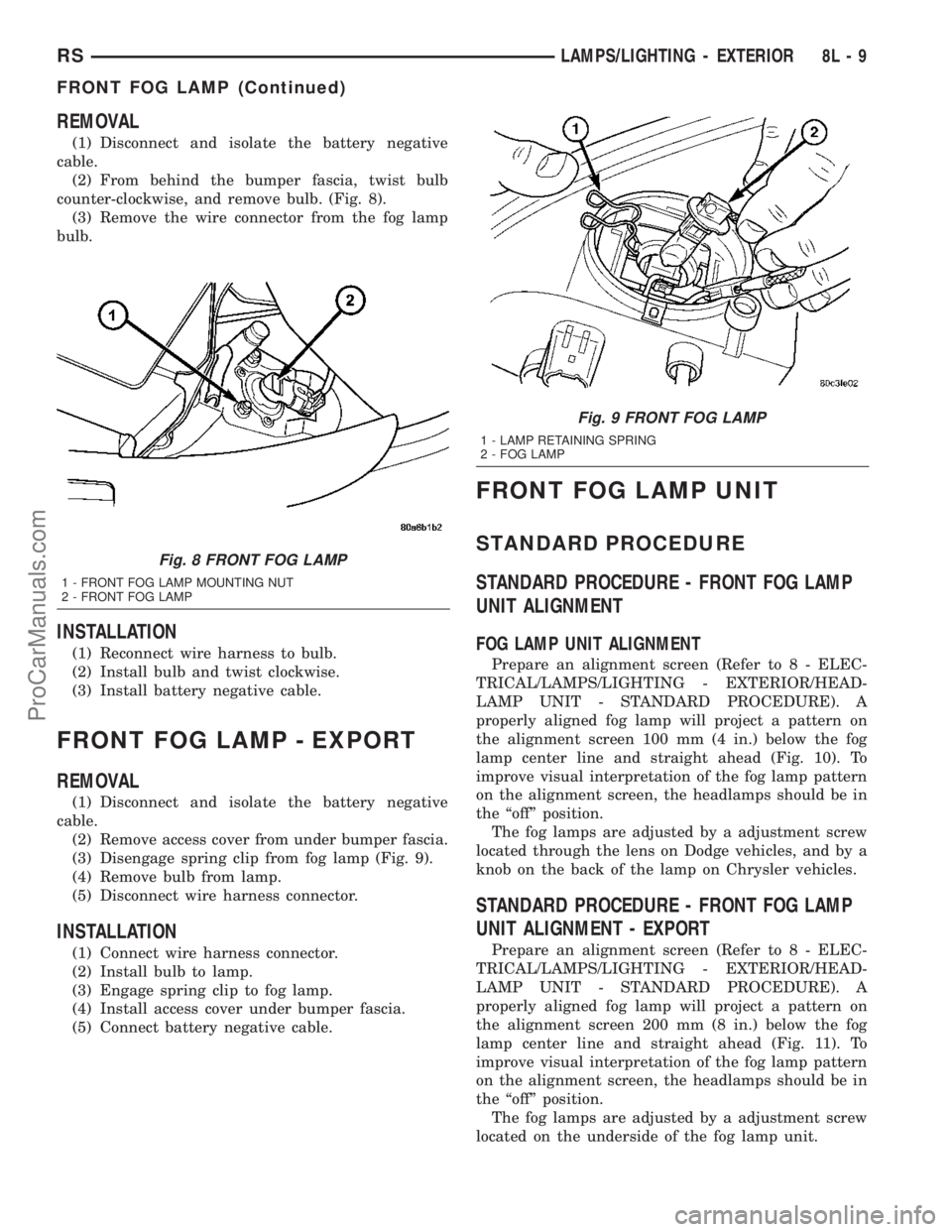
REMOVAL
(1) Disconnect and isolate the battery negative
cable.
(2) From behind the bumper fascia, twist bulb
counter-clockwise, and remove bulb. (Fig. 8).
(3) Remove the wire connector from the fog lamp
bulb.
INSTALLATION
(1) Reconnect wire harness to bulb.
(2) Install bulb and twist clockwise.
(3) Install battery negative cable.
FRONT FOG LAMP - EXPORT
REMOVAL
(1) Disconnect and isolate the battery negative
cable.
(2) Remove access cover from under bumper fascia.
(3) Disengage spring clip from fog lamp (Fig. 9).
(4) Remove bulb from lamp.
(5) Disconnect wire harness connector.
INSTALLATION
(1) Connect wire harness connector.
(2) Install bulb to lamp.
(3) Engage spring clip to fog lamp.
(4) Install access cover under bumper fascia.
(5) Connect battery negative cable.
FRONT FOG LAMP UNIT
STANDARD PROCEDURE
STANDARD PROCEDURE - FRONT FOG LAMP
UNIT ALIGNMENT
FOG LAMP UNIT ALIGNMENT
Prepare an alignment screen (Refer to 8 - ELEC-
TRICAL/LAMPS/LIGHTING - EXTERIOR/HEAD-
LAMP UNIT - STANDARD PROCEDURE). A
properly aligned fog lamp will project a pattern on
the alignment screen 100 mm (4 in.) below the fog
lamp center line and straight ahead (Fig. 10). To
improve visual interpretation of the fog lamp pattern
on the alignment screen, the headlamps should be in
the ªoffº position.
The fog lamps are adjusted by a adjustment screw
located through the lens on Dodge vehicles, and by a
knob on the back of the lamp on Chrysler vehicles.
STANDARD PROCEDURE - FRONT FOG LAMP
UNIT ALIGNMENT - EXPORT
Prepare an alignment screen (Refer to 8 - ELEC-
TRICAL/LAMPS/LIGHTING - EXTERIOR/HEAD-
LAMP UNIT - STANDARD PROCEDURE). A
properly aligned fog lamp will project a pattern on
the alignment screen 200 mm (8 in.) below the fog
lamp center line and straight ahead (Fig. 11). To
improve visual interpretation of the fog lamp pattern
on the alignment screen, the headlamps should be in
the ªoffº position.
The fog lamps are adjusted by a adjustment screw
located on the underside of the fog lamp unit.
Fig. 8 FRONT FOG LAMP
1 - FRONT FOG LAMP MOUNTING NUT
2 - FRONT FOG LAMP
Fig. 9 FRONT FOG LAMP
1 - LAMP RETAINING SPRING
2 - FOG LAMP
RSLAMPS/LIGHTING - EXTERIOR8L-9
FRONT FOG LAMP (Continued)
ProCarManuals.com
Page 425 of 2177

REMOVAL
(1) Disconnect and isolate the battery negative
cable.
(2) From behind the bumper fascia, disconnect the
wire harness from the fog lamp bulb (Fig. 8).
(3) Remove mounting nuts.
INSTALLATION
(1) Install mounting nuts.
(2) Reconnect the wire harness to the fog lamp
bulb.
(3) Reconnect the battery negative cable.
FRONT POSITION LAMP -
EXPORT
REMOVAL
(1) Disconnect and isolate the battery negative
cable.
(2) Remove the headlamp unit (Fig. 12).
(3) Remove the plastic cover from the back of the
headlamp unit.
(4) Pull front position lamp socket from headlamp
unit.
(5) Pull bulb straight out of socket.
INSTALLATION
(1) Push bulb into the bulb socket.
(2) Insert bulb socket into headlamp unit.
(3) Install cover to the back of the headlamp unit.
(4) Install the headlamp unit.
(5) Connect the battery negative cable.
Fig. 10 FRONT FOG LAMP UNIT ALIGNMENT
1 - HIGH INTENSITY AREA 4 - 100MM (4 IN.)
2 - CENTER OF VEHICLE 5 - 7.62 METERS (25 FT.)
3 - HORIZONTAL CENTER OF FOG LAMP 6 - FRONT OF FOG LAMP
8L - 10 LAMPS/LIGHTING - EXTERIORRS
FRONT FOG LAMP UNIT (Continued)
ProCarManuals.com