lug pattern CHRYSLER CARAVAN 2003 Service Manual
[x] Cancel search | Manufacturer: CHRYSLER, Model Year: 2003, Model line: CARAVAN, Model: CHRYSLER CARAVAN 2003Pages: 2177, PDF Size: 59.81 MB
Page 268 of 2177
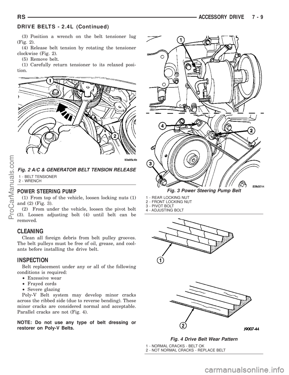
(3) Position a wrench on the belt tensioner lug
(Fig. 2).
(4) Release belt tension by rotating the tensioner
clockwise (Fig. 2).
(5) Remove belt.
(1) Carefully return tensioner to its relaxed posi-
tion.
POWER STEERING PUMP
(1) From top of the vehicle, loosen locking nuts (1)
and (2) (Fig. 3).
(2) From under the vehicle, loosen the pivot bolt
(3). Loosen adjusting bolt (4) until belt can be
removed.
CLEANING
Clean all foreign debris from belt pulley grooves.
The belt pulleys must be free of oil, grease, and cool-
ants before installing the drive belt.
INSPECTION
Belt replacement under any or all of the following
conditions is required:
²Excessive wear
²Frayed cords
²Severe glazing
Poly-V Belt system may develop minor cracks
across the ribbed side (due to reverse bending). These
minor cracks are considered normal and acceptable.
Parallel cracks are not (Fig. 4).
NOTE: Do not use any type of belt dressing or
restorer on Poly-V Belts.
Fig. 2 A/C & GENERATOR BELT TENSION RELEASE
1 - BELT TENSIONER
2 - WRENCH
Fig. 3 Power Steering Pump Belt
1 - REAR LOCKING NUT
2 - FRONT LOCKING NUT
3 - PIVOT BOLT
4 - ADJUSTING BOLT
Fig. 4 Drive Belt Wear Pattern
1 - NORMAL CRACKS - BELT OK
2 - NOT NORMAL CRACKS - REPLACE BELT
RSACCESSORY DRIVE7-9
DRIVE BELTS - 2.4L (Continued)
ProCarManuals.com
Page 270 of 2177
DRIVE BELTS - 3.3/3.8L
REMOVAL
(1) Raise vehicle on hoist.
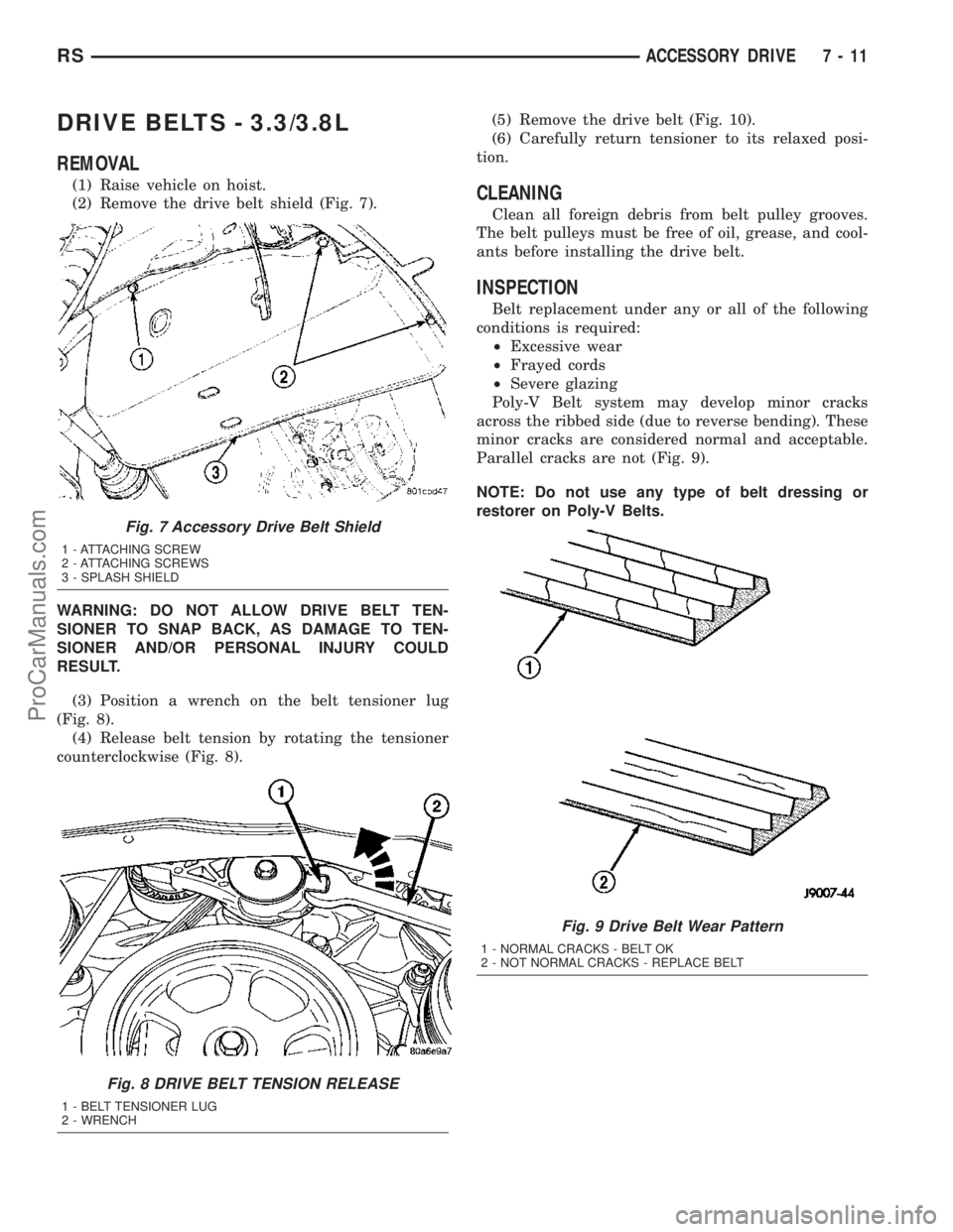
(2) Remove the drive belt shield (Fig. 7).
WARNING: DO NOT ALLOW DRIVE BELT TEN-
SIONER TO SNAP BACK, AS DAMAGE TO TEN-
SIONER AND/OR PERSONAL INJURY COULD
RESULT.
(3) Position a wrench on the belt tensioner lug
(Fig. 8).
(4) Release belt tension by rotating the tensioner
counterclockwise (Fig. 8).(5) Remove the drive belt (Fig. 10).
(6) Carefully return tensioner to its relaxed posi-
tion.CLEANING
Clean all foreign debris from belt pulley grooves.
The belt pulleys must be free of oil, grease, and cool-
ants before installing the drive belt.
INSPECTION
Belt replacement under any or all of the following
conditions is required:
²Excessive wear
²Frayed cords
²Severe glazing
Poly-V Belt system may develop minor cracks
across the ribbed side (due to reverse bending). These
minor cracks are considered normal and acceptable.
Parallel cracks are not (Fig. 9).
NOTE: Do not use any type of belt dressing or
restorer on Poly-V Belts.
Fig. 7 Accessory Drive Belt Shield
1 - ATTACHING SCREW
2 - ATTACHING SCREWS
3 - SPLASH SHIELD
Fig. 8 DRIVE BELT TENSION RELEASE
1 - BELT TENSIONER LUG
2 - WRENCH
Fig. 9 Drive Belt Wear Pattern
1 - NORMAL CRACKS - BELT OK
2 - NOT NORMAL CRACKS - REPLACE BELT
RSACCESSORY DRIVE7-11
ProCarManuals.com
Page 1188 of 2177
(3) Remove torque converter or clutch housing
cover and inspect rear of block for evidence of oil.
Use a black light to check for the oil leak. If a leak is
present in this area, remove transmission for further
inspection.
(a) Circular spray pattern generally indicates
seal leakage or crankshaft damage.
(b) Where leakage tends to run straight down,
possible causes are a porous block, oil gallery cup
plug, bedplate to cylinder block mating surfaces
and seal bore. See proper repair procedures for
these items.
(4) If no leaks are detected, pressurize the crank-
case as previously described.
CAUTION: Do not exceed 20.6 kPa (3 psi).
(5) If the leak is not detected, very slowly turn the
crankshaft and watch for leakage. If a leak is
detected between the crankshaft and seal while
slowly turning the crankshaft, it is possible the
crankshaft seal surface is damaged. The seal area on
the crankshaft could have minor nicks or scratches
that can be polished out with emery cloth.
CAUTION: Use extreme caution when crankshaft
polishing is necessary to remove minor nicks and
scratches. The crankshaft seal flange is especially
machined to complement the function of the rear oil
seal.
(6) For bubbles that remain steady with shaft
rotation, no further inspection can be done until dis-
assembled.
(7) After the oil leak root cause and appropriate
corrective action have been identified, replace compo-
nent(s) as necessary.
DIAGNOSIS AND TESTING - CYLINDER
COMPRESSION PRESSURE TEST
The results of a cylinder compression pressure test
can be utilized to diagnose several engine malfunc-
tions.
Ensure the battery is completely charged and the
engine starter motor is in good operating condition.
Otherwise the indicated compression pressures may
not be valid for diagnosis purposes.
(1) Check engine oil level and add oil if necessary.
(2) Drive the vehicle until engine reaches normal
operating temperature. Select a route free from traf-
fic and other forms of congestion, observe all traffic
laws, and accelerate through the gears several times
briskly.
(3) Remove all spark plugs from engine. As spark
plugs are being removed, check electrodes for abnor-
mal firing indicators fouled, hot, oily, etc. Record cyl-
inder number of spark plug for future reference.(4) Remove the Auto Shutdown (ASD) relay from
the PDC.
(5) Be sure throttle blade is fully open during the
compression check.
(6) Insert compression gauge adaptor Special Tool
8116 or the equivalent, into the #1 spark plug hole in
cylinder head. Connect the 0±500 psi (Blue) pressure
transducer (Special Tool CH7059) with cable adap-
tors to the DRBIIIt. For Special Tool identification,
(Refer to 9 - ENGINE - SPECIAL TOOLS).
(7) Crank engine until maximum pressure is
reached on gauge. Record this pressure as #1 cylin-
der pressure.
(8) Repeat the previous step for all remaining cyl-
inders.
(9) Compression should not be less than 689 kPa
(100 psi) and not vary more than 25 percent from cyl-
inder to cylinder.
(10) If one or more cylinders have abnormally low
compression pressures, repeat the compression test.
(11) If the same cylinder or cylinders repeat an
abnormally low reading on the second compression
test, it could indicate the existence of a problem in
the cylinder in question.The recommended com-
pression pressures are to be used only as a
guide to diagnosing engine problems. An engine
should not be disassembled to determine the
cause of low compression unless some malfunc-
tion is present.
DIAGNOSIS AND TESTING - CYLINDER
COMBUSTION PRESSURE LEAKAGE TEST
The combustion pressure leakage test provides an
accurate means for determining engine condition.
Combustion pressure leakage testing will detect:
²Exhaust and intake valve leaks (improper seat-
ing).
²Leaks between adjacent cylinders or into water
jacket.
²Any causes for combustion/compression pressure
loss.
WARNING: DO NOT REMOVE THE PRESSURE CAP
WITH THE SYSTEM HOT AND UNDER PRESSURE
BECAUSE SERIOUS BURNS FROM COOLANT CAN
OCCUR.
Check the coolant level and fill as required. DO
NOT install the pressure cap.
Start and operate the engine until it attains nor-
mal operating temperature, then turn the engine
OFF.
Clean spark plug recesses with compressed air.
Remove the spark plugs.
Remove the oil filler cap.
Remove the air cleaner.
RSENGINE 2.4L9-9
ENGINE 2.4L (Continued)
ProCarManuals.com
Page 1214 of 2177
INSPECTION
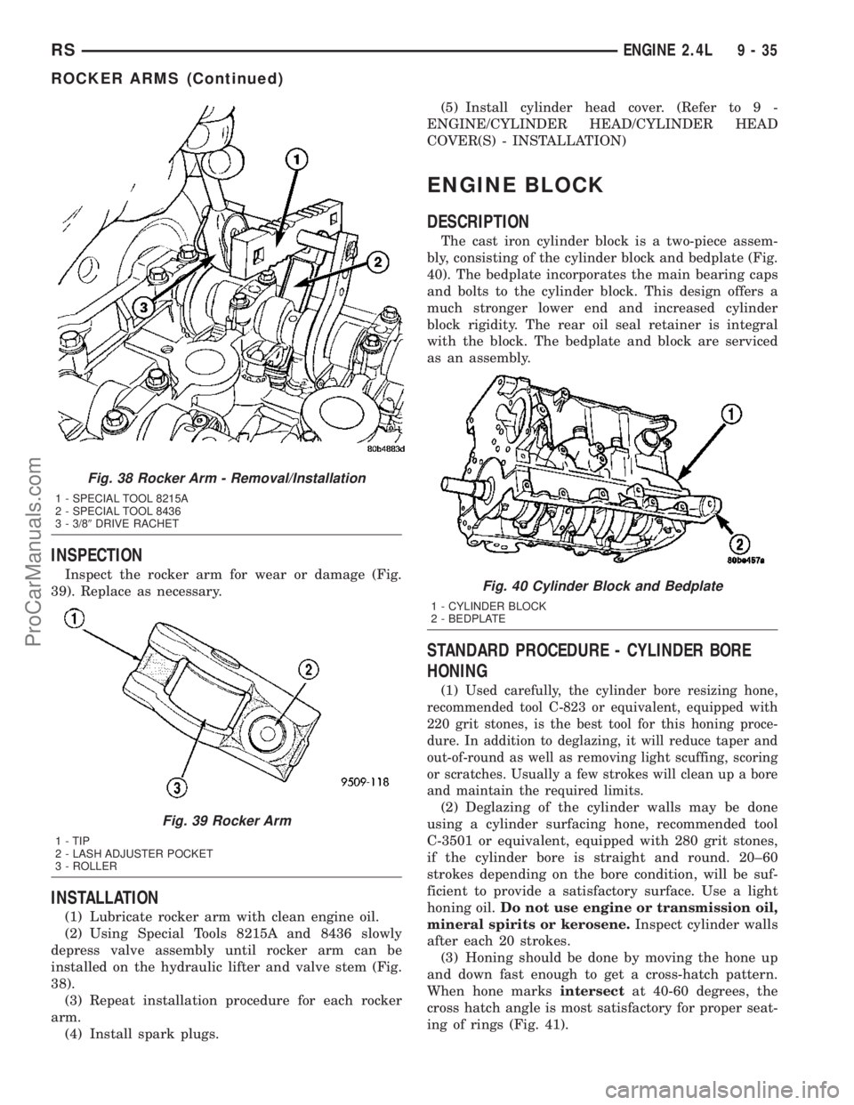
Inspect the rocker arm for wear or damage (Fig.
39). Replace as necessary.
INSTALLATION
(1) Lubricate rocker arm with clean engine oil.
(2) Using Special Tools 8215A and 8436 slowly
depress valve assembly until rocker arm can be
installed on the hydraulic lifter and valve stem (Fig.
38).
(3) Repeat installation procedure for each rocker
arm.
(4) Install spark plugs.(5) Install cylinder head cover. (Refer to 9 -
ENGINE/CYLINDER HEAD/CYLINDER HEAD
COVER(S) - INSTALLATION)
ENGINE BLOCK
DESCRIPTION
The cast iron cylinder block is a two-piece assem-
bly, consisting of the cylinder block and bedplate (Fig.
40). The bedplate incorporates the main bearing caps
and bolts to the cylinder block. This design offers a
much stronger lower end and increased cylinder
block rigidity. The rear oil seal retainer is integral
with the block. The bedplate and block are serviced
as an assembly.
STANDARD PROCEDURE - CYLINDER BORE
HONING
(1)Used carefully, the cylinder bore resizing hone,
recommended tool C-823 or equivalent, equipped with
220 grit stones, is the best tool for this honing proce-
dure. In addition to deglazing, it will reduce taper and
out-of-round as well as removing light scuffing, scoring
or scratches. Usually a few strokes will clean up a bore
and maintain the required limits.
(2) Deglazing of the cylinder walls may be done
using a cylinder surfacing hone, recommended tool
C-3501 or equivalent, equipped with 280 grit stones,
if the cylinder bore is straight and round. 20±60
strokes depending on the bore condition, will be suf-
ficient to provide a satisfactory surface. Use a light
honing oil.Do not use engine or transmission oil,
mineral spirits or kerosene.Inspect cylinder walls
after each 20 strokes.
(3) Honing should be done by moving the hone up
and down fast enough to get a cross-hatch pattern.
When hone marksintersectat 40-60 degrees, the
cross hatch angle is most satisfactory for proper seat-
ing of rings (Fig. 41).
Fig. 38 Rocker Arm - Removal/Installation
1 - SPECIAL TOOL 8215A
2 - SPECIAL TOOL 8436
3 - 3/89DRIVE RACHET
Fig. 39 Rocker Arm
1 - TIP
2 - LASH ADJUSTER POCKET
3 - ROLLER
Fig. 40 Cylinder Block and Bedplate
1 - CYLINDER BLOCK
2 - BEDPLATE
RSENGINE 2.4L9-35
ROCKER ARMS (Continued)
ProCarManuals.com
Page 1215 of 2177

(4) A controlled hone motor speed between
200±300 RPM is necessary to obtain the proper cross-
hatch angle. The number of up and down strokes per
minute can be regulated to get the desired 40±60
degree angle. Faster up and down strokes increase
the cross-hatch angle.
(5) After honing, it is necessary that the block be
cleaned again to remove all traces of abrasive.
CAUTION: Ensure all abrasives are removed from
engine parts after honing. It is recommended that a
solution of soap and hot water be used with a
brush and the parts then thoroughly dried. The bore
can be considered clean when it can be wiped
clean with a white cloth and cloth remains clean.
Oil the bores after cleaning to prevent rusting.
CLEANING
Clean cylinder block thoroughly using a suitable
cleaning solvent.
INSPECTION
ENGINE BLOCK
(1) Clean cylinder block thoroughly and check all
core hole plugs for evidence of leaking.
(2) If new core plugs are to be installed, (Refer to 9
- ENGINE - STANDARD PROCEDURE - ENGINE
CORE AND OIL GALLERY PLUGS).
(3) Examine block and cylinder bores for cracks or
fractures.(4) Check block deck surfaces for flatness. Deck
surface must be within service limit of 0.1 mm (0.004
in.).
CYLINDER BORE
NOTE: The cylinder bores should be measured at
normal room temperature, 21ÉC (70ÉF).
The cylinder walls should be checked for out-of-
round and taper with Tool C119 or equivalent (Fig.
42) (Refer to 9 - ENGINE - SPECIFICATIONS). If
the cylinder walls are badly scuffed or scored, the
cylinder block should be replaced, and new pistons
and rings fitted.
Measure the cylinder bore at three levels in direc-
tions A and B (Fig. 42). Top measurement should be
10 mm (3/8 in.) down and bottom measurement
should be 10 mm (3/8 in.) up from bottom of bore.
(Refer to 9 - ENGINE - SPECIFICATIONS).
CRANKSHAFT
STANDARD PROCEDURE - CRANKSHAFT END
PLAY
(1) Using Dial Indicator C-3339 and Mounting
Post L-4438, attach to front of engine, locating probe
perpendicular on nose of crankshaft (Fig. 43).
(2) Move crankshaft all the way to the rear of its
travel.
(3) Zero the dial indicator.
Fig. 41 Cylinder Bore Cross-Hatch Pattern
1 - CROSS-HATCH PATTERN
2 - 40ɱ60É
Fig. 42 Checking Cylinder Bore Size
9 - 36 ENGINE 2.4LRS
ENGINE BLOCK (Continued)
ProCarManuals.com
Page 1262 of 2177
(3) Remove torque converter or clutch housing
cover and inspect rear of block for evidence of oil.
Use a black light to check for the oil leak. If a leak is
present in this area, remove transmission for further
inspection.
(a) Circular spray pattern generally indicates
seal leakage or crankshaft damage.
(b) Where leakage tends to run straight down,
possible causes are a porous block, oil gallery cup
plug, bedplate to cylinder block mating surfaces
and seal bore. See proper repair procedures for
these items.
(4) If no leaks are detected, pressurize the crank-
case as previously described.
CAUTION: Do not exceed 20.6 kPa (3 psi).
(5) If the leak is not detected, very slowly turn the
crankshaft and watch for leakage. If a leak is
detected between the crankshaft and seal while
slowly turning the crankshaft, it is possible the
crankshaft seal surface is damaged. The seal area on
the crankshaft could have minor nicks or scratches
that can be polished out with emery cloth.
CAUTION: Use extreme caution when crankshaft
polishing is necessary to remove minor nicks and
scratches. The crankshaft seal flange is especially
machined to complement the function of the rear oil
seal.
(6) For bubbles that remain steady with shaft
rotation, no further inspection can be done until dis-
assembled.
(7) After the oil leak root cause and appropriate
corrective action have been identified, replace compo-
nent(s) as necessary.
DIAGNOSIS AND TESTING - CYLINDER
COMPRESSION PRESSURE TEST
The results of a cylinder compression pressure test
can be utilized to diagnose several engine malfunc-
tions.
Ensure the battery is completely charged and the
engine starter motor is in good operating condition.
Otherwise the indicated compression pressures may
not be valid for diagnosis purposes.
(1) Check engine oil level and add oil if necessary.
(2) Drive the vehicle until engine reaches normal
operating temperature. Select a route free from traf-
fic and other forms of congestion, observe all traffic
laws, and accelerate through the gears several times
briskly.
(3) Remove all spark plugs from engine. As spark
plugs are being removed, check electrodes for abnor-
mal firing indicators fouled, hot, oily, etc. Record cyl-
inder number of spark plug for future reference.(4) Remove the Auto Shutdown (ASD) relay from
the PDC.
(5) Be sure throttle blade is fully open during the
compression check.
(6) Insert compression gauge adaptor Special Tool
8116 or the equivalent, into the #1 spark plug hole in
cylinder head. Connect the 0±500 psi (Blue) pressure
transducer (Special Tool CH7059) with cable adap-
tors to the DRBIIIt. For Special Tool identification,
(Refer to 9 - ENGINE - SPECIAL TOOLS).
(7) Crank engine until maximum pressure is
reached on gauge. Record this pressure as #1 cylin-
der pressure.
(8) Repeat the previous step for all remaining cyl-
inders.
(9) Compression should not be less than 689 kPa
(100 psi) and not vary more than 25 percent from cyl-
inder to cylinder.
(10) If one or more cylinders have abnormally low
compression pressures, repeat the compression test.
(11) If the same cylinder or cylinders repeat an
abnormally low reading on the second compression
test, it could indicate the existence of a problem in
the cylinder in question.The recommended com-
pression pressures are to be used only as a
guide to diagnosing engine problems. An engine
should not be disassembled to determine the
cause of low compression unless some malfunc-
tion is present.
DIAGNOSIS AND TESTING - CYLINDER
COMBUSTION PRESSURE LEAKAGE TEST
The combustion pressure leakage test provides an
accurate means for determining engine condition.
Combustion pressure leakage testing will detect:
²Exhaust and intake valve leaks (improper seat-
ing).
²Leaks between adjacent cylinders or into water
jacket.
²Any causes for combustion/compression pressure
loss.
WARNING: DO NOT REMOVE THE PRESSURE CAP
WITH THE SYSTEM HOT AND UNDER PRESSURE
BECAUSE SERIOUS BURNS FROM COOLANT CAN
OCCUR.
Check the coolant level and fill as required. DO
NOT install the pressure cap.
Start and operate the engine until it attains nor-
mal operating temperature, then turn the engine
OFF.
Clean spark plug recesses with compressed air.
Remove the spark plugs.
Remove the oil filler cap.
Remove the air cleaner.
RSENGINE 3.3/3.8L9-83
ENGINE 3.3/3.8L (Continued)
ProCarManuals.com
Page 1291 of 2177
REMOVAL
(1) Remove the valve springs. (Refer to 9 -
ENGINE/CYLINDER HEAD/VALVE SPRINGS -
REMOVAL)
(2) Remove the valve stem seal (Fig. 43).
INSTALLATION
(1) Install the valve stem seal squarely over the
valve guide, using the valve stem as a guide (Fig.
43). Do not force the seal against top of the valve
guide.
(2) Install the valve spring. (Refer to 9 - ENGINE/
CYLINDER HEAD/VALVE SPRINGS - INSTALLA-
TION)
ENGINE BLOCK
DESCRIPTION
The cylinder block is made of cast iron and is a
deep skirt design.
STANDARD PROCEDURE - CYLINDER BORE
HONING
(1) Used carefully, the cylinder bore resizing hone,
recommended tool C-823 or equivalent, equipped
with 220 grit stones, is the best tool for this honing
procedure. In addition to deglazing, it will reduce
taper and out-of-round as well as removing light
scuffing, scoring or scratches. Usually a few strokes
will clean up a bore and maintain the required lim-
its.
(2) Deglazing of the cylinder walls may be done
using a cylinder surfacing hone, recommended tool
C-3501 or equivalent, equipped with 280 grit stones,
if the cylinder bore is straight and round. 20±60
strokes depending on the bore condition, will be suf-
ficient to provide a satisfactory surface. Use a light
honing oil.Do not use engine or transmission oil,
mineral spirits or kerosene.Inspect cylinder walls
after each 20 strokes.
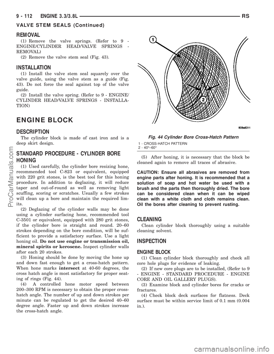
(3) Honing should be done by moving the hone up
and down fast enough to get a cross-hatch pattern.
When hone marksintersectat 40-60 degrees, the
cross hatch angle is most satisfactory for proper seat-
ing of rings (Fig. 44).
(4) A controlled hone motor speed between
200±300 RPM is necessary to obtain the proper cross-
hatch angle. The number of up and down strokes per
minute can be regulated to get the desired 40±60
degree angle. Faster up and down strokes increase
the cross-hatch angle.(5) After honing, it is necessary that the block be
cleaned again to remove all traces of abrasive.
CAUTION: Ensure all abrasives are removed from
engine parts after honing. It is recommended that a
solution of soap and hot water be used with a
brush and the parts then thoroughly dried. The bore
can be considered clean when it can be wiped
clean with a white cloth and cloth remains clean.
Oil the bores after cleaning to prevent rusting.
CLEANING
Clean cylinder block thoroughly using a suitable
cleaning solvent.
INSPECTION
ENGINE BLOCK
(1) Clean cylinder block thoroughly and check all
core hole plugs for evidence of leaking.
(2) If new core plugs are to be installed, (Refer to 9
- ENGINE - STANDARD PROCEDURE - ENGINE
CORE AND OIL GALLERY PLUGS).
(3) Examine block and cylinder bores for cracks or
fractures.
(4) Check block deck surfaces for flatness. Deck
surface must be within service limit of 0.1 mm (0.004
in.).
Fig. 44 Cylinder Bore Cross-Hatch Pattern
1 - CROSS-HATCH PATTERN
2 - 40ɱ60É
9 - 112 ENGINE 3.3/3.8LRS
VALVE STEM SEALS (Continued)
ProCarManuals.com
Page 1520 of 2177

INSTALLATION
(1) Install gearshift boot to console and secure
with three (3) retaining clips (Fig. 130).
(2) Install gearshift knob (Fig. 129). Orient shift
pattern
1¤4-turn clockwise, press down, and rotate1¤4-
turn counter-clockwise.
(3) Secure gearshift boot to base of knob.
GEARSHIFT CABLE -
CROSSOVER
REMOVAL
(1) Disconnect battery negative cable.
(2) Remove gearshift knob by pushing down and
rotating
1¤4-turn clock-wise (Fig. 131).
(3) Remove gearshift boot from center console by
disengaging at three (3) retaining clips (Fig. 132).
(4) Apply park brake to allow park brake handle to
clear center console upon removal.
(5) Remove two (2) cupholder bottom plugs (Fig.
133).
Fig. 131 Gearshift Knob Removal/Installation
1 - GEARSHIFT KNOB
2 - GEARSHIFT LEVER
Fig. 132 Gearshift Boot Removal/Installation
1 - GEARSHIFT BOOT
2 - CENTER CONSOLE
Fig. 133 Cup Holder Plugs
1 - CUPHOLDER PLUG (2)
RST850 MANUAL TRANSAXLE21-73
GEARSHIFT BOOT (Continued)
ProCarManuals.com
Page 1527 of 2177

(4) Apply park brake to allow park brake handle to
clear center console upon removal.
(5) Remove two (2) cupholder bottom plugs (Fig.
157).
(6) Remove four (4) center console-to-gearshift
mechanism screws. Remove console assembly (Fig.
158).(7) Loosen crossover cable adjustment screw (Fig.
159).
(8) Rock gearshift lever back and forth between
1±2 and 5±R planes. Release lever, allowing shifter
spring to return lever to the neutral position in the
3±4 plane. Place gearshift lever in the 3rd gear posi-
tion.
(9) Torque crossover lever adjustment screw to 8
N´m (70 in. lbs.).No load should be applied to
the shifter lever in any direction (hands off)
while tightening screw.
(10) Verify gearshift lever travel through all gear
ranges with engine off (not running).
(11) Install center console assembly (Fig. 158).
Install and torque center console-to-gearshift mecha-
nism screws to 5 N´m (45 in. lbs.).
(12) Install cupholder plugs (Fig. 157).
(13) Install gearshift boot to console (Fig. 156).
Secure boot to console with three (3) retainer clips.
(14) Install gearshift knob to gearshift lever (Fig.
155). Orient shift pattern on knob
1¤4-turn clockwise,
push down and rotate1¤4-turn counter-clockwise and
release. Secure boot to knob.
(15) Connect battery negative cable.
Fig. 157 Cup Holder Plugs
1 - CUPHOLDER PLUG (2)
Fig. 158 Center Console Removal/Installation (LHD
Shown Ð RHD Typical)
1 - CENTER CONSOLE
2 - SCREW (4)
3 - GEARSHIFT MECHANISM
Fig. 159 Crossover Cable Adjustment Screw
1 - CROSSOVER CABLE
2 - ADJUSTMENT SCREW
21 - 80 T850 MANUAL TRANSAXLERS
GEARSHIFT CABLE - CROSSOVER (Continued)
ProCarManuals.com
Page 1539 of 2177

(7) Install cupholder plugs (Fig. 202).
(8) Install gearshift boot to console (Fig. 203).
Secure with three (3) retainer clips.(9) Install gearshift knob to gearshift lever (Fig.
204). Orient shift pattern1¤4-turn clockwise, push
down and rotate1¤4-turn counter-clockwise and
release. Secure boot to knob.
(10) Connect battery negative cable.
Fig. 202 Cup Holder Plugs
1 - CUPHOLDER PLUG (2)
Fig. 203 Gearshift Boot Removal/Installation
1 - GEARSHIFT BOOT
2 - CENTER CONSOLE
Fig. 204 Gearshift Knob Removal/Installation
1 - GEARSHIFT KNOB
2 - GEARSHIFT LEVER
21 - 92 T850 MANUAL TRANSAXLERS
GEARSHIFT MECHANISM (Continued)
ProCarManuals.com