remote control CHRYSLER CARAVAN 2003 Service Manual
[x] Cancel search | Manufacturer: CHRYSLER, Model Year: 2003, Model line: CARAVAN, Model: CHRYSLER CARAVAN 2003Pages: 2177, PDF Size: 59.81 MB
Page 301 of 2177
CONDITION POSSIBLE CAUSE CORRECTION
HEADPHONES
WILL NOT HOLD
A CHANNEL OR
HAVE STATIC1. WEAK BATTERIES IN
THE HEADPHONES.1. REPLACE BATTERIES.
2. CLOSENESS TO
RADIO TRANSMITTER
SUCH AS A RADIO
TOWER, AIRPORT
TRANSMITTER OR
SOME MOBILE
RADIOS.2. MOVE TO AN AREA AWAY FREE FROM THESE
CONDITIONS.
REMOTE
CONTROL
INOPERATIVE1. WEAK BATTERIES IN
THE REMOTE
CONTROL.1. REPLACE BATTERIES.
2. OPERATION
CONSTRAINT OF
SYSTEM2. MAKE SURE THAT REAR AUDIO IS IN A DIFFERENT MODE
THAN FRONT SPEAKERS. REMOTE CONTROL WILL NOT
WORK WHEN BOTH ARE IN THE SAME MODE.
ANTENNA BODY AND CABLE
DESCRIPTION
All models use a fixed-length stainless steel rod-
type antenna mast, installed at the right front fender
of the vehicle. The antenna mast is connected to the
center wire of the coaxial antenna cable, and is not
grounded to any part of the vehicle.
OPERATION
To minimize static, the antenna base must have a
good ground. The coaxial antenna cable shield (the
outer wire mesh of the cable) is grounded to the
antenna base and the radio chassis.
The antenna coaxial cable has an additional dis-
connect, located near the right end of the instrument
panel. This additional disconnect allows the instru-
ment panel assembly to be removed and installed
without removing the radio.
DIAGNOSIS AND TESTING - ANTENNA BODY
AND CABLE
WARNING: ON VEHICLES EQUIPPED WITH AIR-
BAGS, REFER TO ELECTRICAL, RESTRAINTS
BEFORE ATTEMPTING ANY STEERING WHEEL,
STEERING COLUMN, OR INSTRUMENT PANEL
COMPONENT DIAGNOSIS OR SERVICE. FAILURE
TO TAKE THE PROPER PRECAUTIONS COULD
RESULT IN ACCIDENTAL AIRBAG DEPLOYMENT
AND POSSIBLE PERSONAL INJURY.
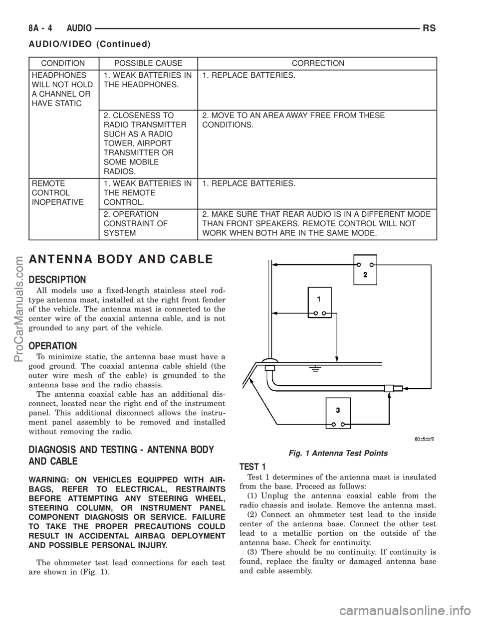
The ohmmeter test lead connections for each test
are shown in (Fig. 1).
TEST 1
Test 1 determines of the antenna mast is insulated
from the base. Proceed as follows:
(1) Unplug the antenna coaxial cable from the
radio chassis and isolate. Remove the antenna mast.
(2) Connect an ohmmeter test lead to the inside
center of the antenna base. Connect the other test
lead to a metallic portion on the outside of the
antenna base. Check for continuity.
(3) There should be no continuity. If continuity is
found, replace the faulty or damaged antenna base
and cable assembly.
Fig. 1 Antenna Test Points
8A - 4 AUDIORS
AUDIO/VIDEO (Continued)
ProCarManuals.com
Page 304 of 2177
DIAGNOSIS AND TESTING - ANTENNA MODULE - EXPORT
CONDITION POSSIBLE CAUSES CORRECTION
NO AM RECEPTION,
WEAK FM RECEPTION1. Antenna module to antenna
connector open or disconnected.1. Repair open, reconnect
antenna module connector to
glass mounted antenna.
2. Coax open or disconnected. 2. Repair open, reconnect coax.
3. No battery power at antenna
module.3. Check fuse. if okay, repair
open in battery voltage circuit.
NO AM OR FM
RECEPTION1. Coax disconnected at radio. 1. Reconnect coax.
2. Coax shorted to ground. 2. Repair or Replace coax
WEAK OR NO AM/FM
RECEPTION1. Antenna Module faulty. 1. Substitute known good
module. If reception improves,
Antenna Module was faulty.
REMOVAL
(1) Disconnect and isolate the battery negative
cable.
(2) Lower headliner as necessary to access
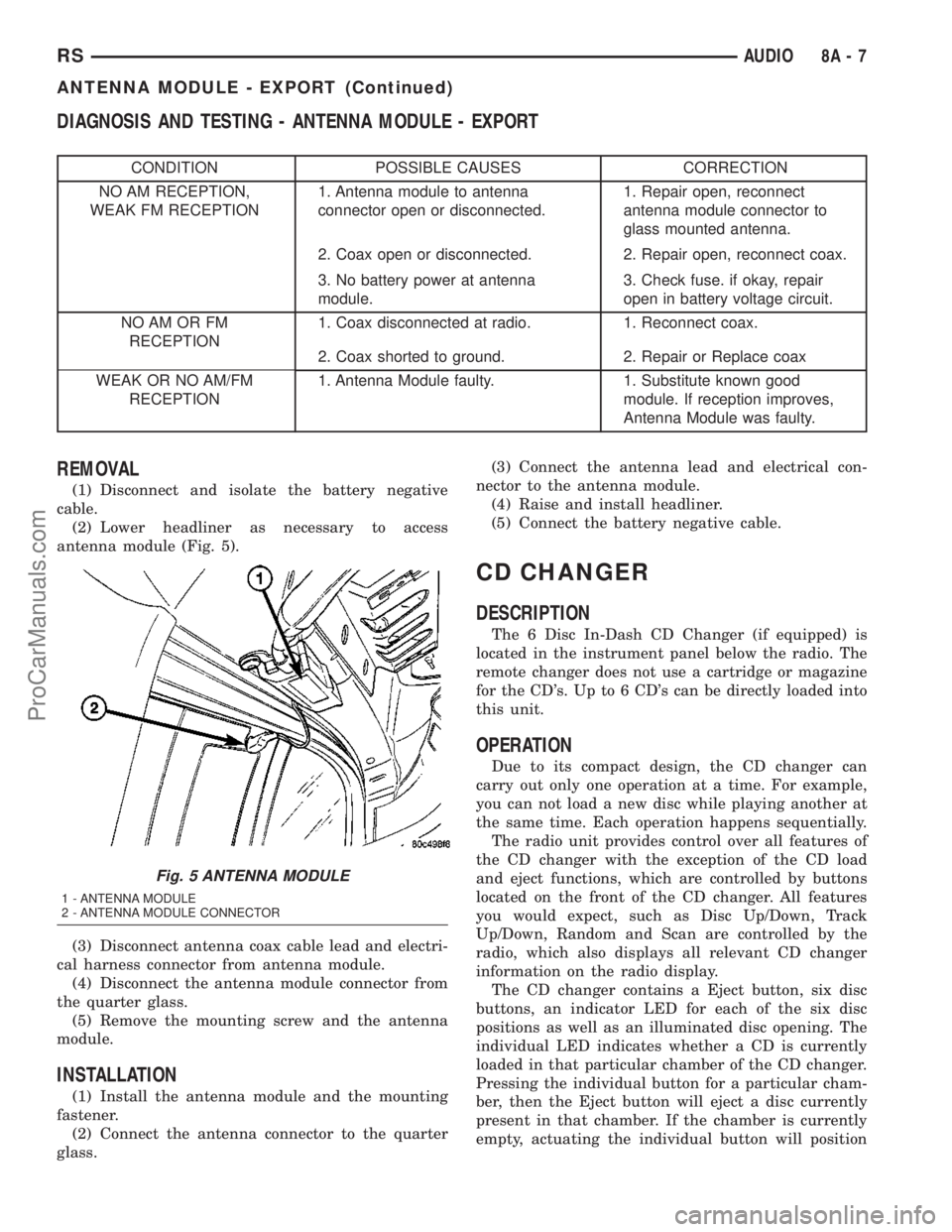
antenna module (Fig. 5).
(3) Disconnect antenna coax cable lead and electri-
cal harness connector from antenna module.
(4) Disconnect the antenna module connector from
the quarter glass.
(5) Remove the mounting screw and the antenna
module.
INSTALLATION
(1) Install the antenna module and the mounting
fastener.
(2) Connect the antenna connector to the quarter
glass.(3) Connect the antenna lead and electrical con-
nector to the antenna module.
(4) Raise and install headliner.
(5) Connect the battery negative cable.
CD CHANGER
DESCRIPTION
The 6 Disc In-Dash CD Changer (if equipped) is
located in the instrument panel below the radio. The
remote changer does not use a cartridge or magazine
for the CD's. Up to 6 CD's can be directly loaded into
this unit.
OPERATION
Due to its compact design, the CD changer can
carry out only one operation at a time. For example,
you can not load a new disc while playing another at
the same time. Each operation happens sequentially.
The radio unit provides control over all features of
the CD changer with the exception of the CD load
and eject functions, which are controlled by buttons
located on the front of the CD changer. All features
you would expect, such as Disc Up/Down, Track
Up/Down, Random and Scan are controlled by the
radio, which also displays all relevant CD changer
information on the radio display.
The CD changer contains a Eject button, six disc
buttons, an indicator LED for each of the six disc
positions as well as an illuminated disc opening. The
individual LED indicates whether a CD is currently
loaded in that particular chamber of the CD changer.
Pressing the individual button for a particular cham-
ber, then the Eject button will eject a disc currently
present in that chamber. If the chamber is currently
empty, actuating the individual button will position
Fig. 5 ANTENNA MODULE
1 - ANTENNA MODULE
2 - ANTENNA MODULE CONNECTOR
RSAUDIO8A-7
ANTENNA MODULE - EXPORT (Continued)
ProCarManuals.com
Page 307 of 2177
grid can be repaired using a Mopar Rear Window
Defogger Repair Kit (Part Number 4267922) or
equivalent. (Refer to 8 - ELECTRICAL/HEATED
GLASS/WINDSHIELD GRID - STANDARD PROCE-
DURE).
RADIO
DESCRIPTION
Available factory-installed radio receivers for this
model include:
²AM/FM/cassette/CD (RAZ sales code)
²AM/FM/CD with CD changer control (RBK sales
code)
²AM/FM/cassette with CD changer control fea-
ture (RBB sales code)
²AM/FM/cassette/CD with rear audio (RBU sales
code)
All factory-installed radio receivers can communi-
cate on the Programmable Communications Interface
(PCI) data bus network. All factory-installed receiv-
ers are stereo Electronically Tuned Radios (ETR) and
include an electronic digital clock function.
These radio receivers can only be serviced by an
authorized radio repair station. See the latest War-
ranty Policies and Procedures manual for a current
listing of authorized radio repair stations.
OPERATION
The radio receiver operates on ignition switched
battery current that is available only when the igni-
tion switch is in the On or Accessory/Accessory Delay
positions. The electronic digital clock function of the
radio operates on fused battery current supplied
through the IOD fuse, regardless of the ignition
switch position.
For more information on the features, setting pro-
cedures, and control functions for each of the avail-
able factory-installed radio receivers, refer to the
owner's manual. For complete circuit diagrams, refer
to the appropriate wiring information. The wiring
information includes wiring diagrams, proper wire
and connector repair procedures, details of wire har-
ness routing and retention, connector pin-out infor-
mation and location views for the various wire
harness connectors, splices and grounds.
DIAGNOSIS AND TESTING - RADIO
WARNING: ON VEHICLES EQUIPPED WITH AIR-
BAGS, REFER TO ELECTRICAL, RESTRAINTS
BEFORE ATTEMPTING ANY STEERING WHEEL,
STEERING COLUMN, OR INSTRUMENT PANEL
COMPONENT DIAGNOSIS OR SERVICE. FAILURE
TO TAKE THE PROPER PRECAUTIONS COULDRESULT IN ACCIDENTAL AIRBAG DEPLOYMENT
AND POSSIBLE PERSONAL INJURY.
Any diagnosis of the Audio system should
begin with the use of the DRB IIItdiagnostic
tool. For information on the use of the DRB
IIIt, refer to the appropriate Diagnostic Service
Manual.
Refer to the appropriate wiring information. The
wiring information includes wiring diagrams, proper
wire and connector repair procedures, details of wire
harness routing and retention, connector pin-out
information and location views for the various wire
harness connectors, splices and grounds.
If the vehicle is equipped with remote radio
switches located on the back of the steering wheel
spokes, and the problem being diagnosed is related to
one of the symptoms listed below, be certain to check
the remote radio switches and circuits as described
in this group, prior to attempting radio diagnosis or
repair.
²Stations changing with no remote radio switch
input
²Radio memory presets not working properly
²Volume changes with no remote radio switch
input
²Remote radio switch buttons taking on other
functions
²CD player skipping tracks
²Remote radio switch inoperative.
CAUTION: The speaker output of the radio is a
ªfloating groundº system. Do not allow any speaker
lead to short to ground, as damage to the radio
may result.
(1) Check the fuse(s) in the junction block and the
Integrated Power Module (IPM). If OK, go to Step 2.
If not OK, repair the shorted circuit or component as
required and replace the faulty fuse(s).
(2) Check for battery voltage at the fuse in the
(IPM). If OK, go to Step 3. If not OK, repair the open
circuit to the battery as required.
(3) Turn the ignition switch to the ON position.
Check for battery voltage at the fuse in the junction
block. If OK, go to Step 4. If not OK, repair the open
circuit to the ignition switch as required.
(4) Turn the ignition switch to the OFF position.
Remove the radio, but do not unplug the wire har-
ness connectors. Check for continuity between the
radio chassis and a good ground. There should be
continuity. If OK, go to Step 5. If not OK, repair the
open radio chassis ground circuit as required.
(5) Connect the battery negative cable. Turn the
ignition switch to the ON position. Check for battery
voltage at the fused ignition switch output circuit
cavity of the radio wire harness connector. If OK, go
8A - 10 AUDIORS
QUARTER GLASS INTEGRAL ANTENNA - EXPORT (Continued)
ProCarManuals.com
Page 309 of 2177
motors, and fuel pumps that have been found to be
potential sources of RFI or EMI.
OPERATION
There are two common strategies that can be used
to suppress Radio Frequency Interference (RFI) and
ElectroMagnetic Interference (EMI) radio noise. The
first suppression strategy involves preventing the
production of RFI and EMI electromagnetic signals
at their sources. The second suppression strategy
involves preventing the reception of RFI and EMI
electromagnetic signals by the audio system compo-
nents.
The use of braided ground straps in key locations
is part of the RFI and EMI prevention strategy.
These ground straps ensure adequate ground paths,
particularly for high current components such as
many of those found in the starting, charging, igni-
tion, engine control and transmission control sys-
tems. An insufficient ground path for any of these
high current components may result in radio noise
caused by induced voltages created as the high cur-
rent seeks alternative ground paths through compo-
nents or circuits intended for use by, or in close
proximity to the audio system components or circuits.
Preventing the reception of RFI and EMI is accom-
plished by ensuring that the audio system compo-
nents are correctly installed in the vehicle. Loose,
corroded or improperly soldered wire harness connec-
tions, improperly routed wiring and inadequate audio
system component grounding can all contribute to
the reception of RFI and EMI. A properly grounded
antenna body and radio chassis, as well as a shielded
antenna coaxial cable with clean and tight connec-
tions will each help reduce the potential for reception
of RFI and EMI.
REMOTE SWITCHES
DESCRIPTION
A remote radio control switch option is available on
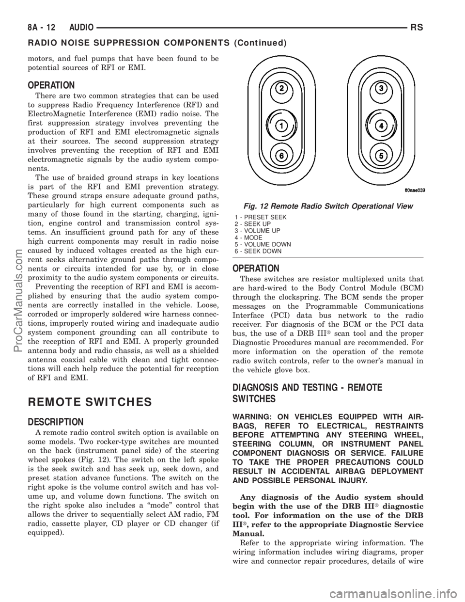
some models. Two rocker-type switches are mounted
on the back (instrument panel side) of the steering
wheel spokes (Fig. 12). The switch on the left spoke
is the seek switch and has seek up, seek down, and
preset station advance functions. The switch on the
right spoke is the volume control switch and has vol-
ume up, and volume down functions. The switch on
the right spoke also includes a ªmodeº control that
allows the driver to sequentially select AM radio, FM
radio, cassette player, CD player or CD changer (if
equipped).
OPERATION
These switches are resistor multiplexed units that
are hard-wired to the Body Control Module (BCM)
through the clockspring. The BCM sends the proper
messages on the Programmable Communications
Interface (PCI) data bus network to the radio
receiver. For diagnosis of the BCM or the PCI data
bus, the use of a DRB IIItscan tool and the proper
Diagnostic Procedures manual are recommended. For
more information on the operation of the remote
radio switch controls, refer to the owner's manual in
the vehicle glove box.
DIAGNOSIS AND TESTING - REMOTE
SWITCHES
WARNING: ON VEHICLES EQUIPPED WITH AIR-
BAGS, REFER TO ELECTRICAL, RESTRAINTS
BEFORE ATTEMPTING ANY STEERING WHEEL,
STEERING COLUMN, OR INSTRUMENT PANEL
COMPONENT DIAGNOSIS OR SERVICE. FAILURE
TO TAKE THE PROPER PRECAUTIONS COULD
RESULT IN ACCIDENTAL AIRBAG DEPLOYMENT
AND POSSIBLE PERSONAL INJURY.
Any diagnosis of the Audio system should
begin with the use of the DRB IIItdiagnostic
tool. For information on the use of the DRB
IIIt, refer to the appropriate Diagnostic Service
Manual.
Refer to the appropriate wiring information. The
wiring information includes wiring diagrams, proper
wire and connector repair procedures, details of wire
Fig. 12 Remote Radio Switch Operational View
1 - PRESET SEEK
2 - SEEK UP
3 - VOLUME UP
4 - MODE
5 - VOLUME DOWN
6 - SEEK DOWN
8A - 12 AUDIORS
RADIO NOISE SUPPRESSION COMPONENTS (Continued)
ProCarManuals.com
Page 310 of 2177

harness routing and retention, connector pin-out
information and location views for the various wire
harness connectors, splices and grounds.
(1) Disconnect and isolate the battery negative
cable. Wait two minutes for the airbag system capac-
itor to discharge before further service.
(2) Remove the remote radio switch(es) from the
steering wheel (Fig. 13). (Refer to 8 - ELECTRICAL/
AUDIO/REMOTE SWITCHES - REMOVAL).
(3) Use an ohmmeter to check the switch resis-
tance as shown in the Remote Radio Switch Test
table.
REMOTE RADIO SWITCH TEST
Switch Switch Position Resistance
Right
(White)Volume Up 1.210 Kilohms
Right
(White)Volume Down 3.010 Kilohms
Right
(White)Mode Advance 0.0511 Kilohms
Left
(Black)Seek Up 0.261 Kilohms
Left
(Black)Seek Down 0.681 Kilohms
Left
(Black)Pre-Set Station
Advance0.162 Kilohms
NOTE: The right remote radio switch back is white
in color. The left switch back is black in color. The
right/left remote radio switch orientation is with the
steering wheel installed, and driver in drivers seat.(4) If the switch resistance checks OK, go to Step
5. If not OK, replace the faulty switch.
(5) Check for continuity between the ground cir-
cuit cavity of the switch wire harness connector and
a good ground. There should be continuity. If OK, go
to Step 6. If not OK, repair the open circuit as
required.
(6) Unplug the 24-way white wire harness connec-
tor from the Body Control Module (BCM). Check for
continuity between the radio control circuit cavity of
the remote radio switch wire harness connector and a
good ground. There should be no continuity. If OK, go
to Step 7. If not OK, repair the short circuit as
required.
(7) Check for continuity between the radio control
circuit cavities of the remote radio switch wire har-
ness connector and the BCM wire harness connector.
There should be continuity. If OK, refer to the proper
Diagnostic Procedures manual to test the BCM and
the PCI data bus. If not OK, repair the open circuit
as required.
REMOVAL
WARNING: ON VEHICLES EQUIPPED WITH AIR-
BAGS, REFER TO ELECTRICAL, RESTRAINTS
BEFORE ATTEMPTING ANY STEERING WHEEL,
STEERING COLUMN, OR INSTRUMENT PANEL
COMPONENT DIAGNOSIS OR SERVICE. FAILURE
TO TAKE THE PROPER PRECAUTIONS COULD
RESULT IN ACCIDENTAL AIRBAG DEPLOYMENT
AND POSSIBLE PERSONAL INJURY.
(1) Disconnect and isolate the battery negative
cable. Wait two minutes for the airbag system capac-
itor to discharge before further service.
(2) Remove the driver side airbag module from the
vehicle. Refer to ELECTRICAL/RESTRAINTS/
DRIVER AIR BAG.
(3) Remove the steering wheel from the steering
column. Refer to STEERING/COLUMN/STEERING
WHEEL.
(4) Unplug the wire harness connector from the
remote radio switch (s).
(5) Remove three screws securing steering wheel
rear cover.
(6) Remove the remote radio switch from the steer-
ing wheel by depressing tabs on each side of each
switch.
NOTE: The right remote radio switch back is white
in color. The left switch back is black in color. The
right/left remote radio switch orientation is with the
steering wheel installed, and driver in drivers seat.
Fig. 13 REMOTE RADIO SWITCHES
1 - BLACK (LEFT) SWITCH
2 - WHITE (RIGHT) SWITCH
RSAUDIO8A-13
REMOTE SWITCHES (Continued)
ProCarManuals.com
Page 311 of 2177
INSTALLATION
WARNING: ON VEHICLES EQUIPPED WITH AIR-
BAGS, REFER TO ELECTRICAL, RESTRAINTS
BEFORE ATTEMPTING ANY STEERING WHEEL,
STEERING COLUMN, OR INSTRUMENT PANEL
COMPONENT DIAGNOSIS OR SERVICE. FAILURE
TO TAKE THE PROPER PRECAUTIONS COULD
RESULT IN ACCIDENTAL AIRBAG DEPLOYMENT
AND POSSIBLE PERSONAL INJURY.
(1) Install remote radio switch to the steering
wheel.
(2) Install three screws securing steering wheel
rear cover.
(3) Connect the wire harness to the remote radio
switch.
(4) Install the steering wheel. Refer to STEERING/
COLUMN/STEERING WHEEL.
(5) Install the driver side airbag module. Refer to
ELECTRICAL/RESTRAINTS/DRIVER AIRBAG.
(6) Connect the battery negative cable.
SPEAKER
DIAGNOSIS AND TESTING - SPEAKER
WARNING: DISABLE THE AIRBAG SYSTEM
BEFORE ATTEMPTING ANY STEERING WHEEL,
STEERING COLUMN, SEAT BELT TENSIONER, SIDE
AIRBAG, OR INSTRUMENT PANEL COMPONENT
DIAGNOSIS OR SERVICE. DISCONNECT AND ISO-
LATE THE BATTERY NEGATIVE (GROUND) CABLE,
THEN WAIT TWO MINUTES FOR THE AIRBAG SYS-
TEM CAPACITOR TO DISCHARGE BEFORE PER-
FORMING FURTHER DIAGNOSIS OR SERVICE. THIS
IS THE ONLY SURE WAY TO DISABLE THE AIRBAG
SYSTEM. FAILURE TO TAKE THE PROPER PRE-
CAUTIONS COULD RESULT IN ACCIDENTAL AIR-
BAG DEPLOYMENT AND POSSIBLE PERSONAL
INJURY.
Any diagnosis of the Audio system should
begin with the use of the DRB IIItdiagnostic
tool. For information on the use of the DRB
IIIt, refer to the appropriate Diagnostic Service
Manual.
Refer to the appropriate wiring information. The
wiring information includes wiring diagrams, proper
wire and connector repair procedures, details of wire
harness routing and retention, connector pin-out
information and location views for the various wire
harness connectors, splices and grounds.
CAUTION: The speaker output of the radio is a
ªfloating groundº system. Do not allow any speakerlead to short to ground, as damage to the radio
may result.
(1) If all speakers are inoperative, check the radio
fuses in the junction block. If OK, go to Step 2. If not
OK, repair the shorted circuit or component as
required and replace the faulty fuse.
(2) Turn the ignition switch to the ON position.
Turn the radio receiver ON. Adjust the balance and
fader control controls to check the performance of
each individual speaker. Note the speaker locations
that are not performing correctly. Go to Step 3.
(3) Turn the radio receiver OFF. Turn the ignition
OFF. Disconnect and isolate the battery negative
cable. Remove the radio receiver.
(4) Check both the speaker feed (+) circuit and
return (-) circuit cavities for the inoperative speaker
at the radio receiver wire harness connector for con-
tinuity to ground. There should be no continuity. If
OK, go to Step 5. If not OK, repair the shorted
speaker feed (+) and/or return (-) circuits(s) to the
speaker as required.
(5) Disconnect wire harness connector at the inop-
erative speaker. Check for continuity between the
speaker feed (+) circuit cavities of the radio receiver
wire harness connector and the speaker wire harness
connector. Repeat the check between the speaker
return (-) circuit cavities of the radio receiver wire
harness connector and the speaker wire harness con-
nector. In each case, there should be continuity. If
OK, replace the faulty speaker. If not OK, repair the
open speaker feed (+) and/or return (-) circuits(s) as
required.
REMOVAL
D-PILLAR SPEAKER
(1) Disconnect and isolate the battery negative
cable.
(2) Remove rear header trim (right side speaker).
(3) Remove jack cover (left side speaker).
(4) Remove liftgate scuff plate.
(5) Remove upper seat belt bolt. (Refer to 8 -
ELECTRICAL/RESTRAINTS/SEAT BELT OUT-
BOARD FRONT - REMOVAL).
(6) Partially remove quarter trim panel to access
the D-pillar speaker.
(7) Slide the speaker from the retainer (Fig. 14).
(8) Disconnect the wire harness connector from the
speaker.
FRONT DOOR SPEAKER
(1) Disconnect and isolate the battery negative
cable.
(2) Remove the front door trim panel. (Refer to 23
- BODY/DOOR - FRONT/TRIM PANEL - REMOV-
AL).
8A - 14 AUDIORS
REMOTE SWITCHES (Continued)
ProCarManuals.com
Page 318 of 2177
(5) Obtain ignition keys to be programmed from
customer (8 keys maximum).
(6) Using the DRB III, erase all ignition keys by
selecting MISCELLANEOUS and ERASE ALL CUR-
RENT IGN. KEYS.
(7) Program all ignition keys.
Learned Key In Ignition - Ignition key transponder
ID is currently programmed in SKIM memory.
BODY CONTROL MODULE
DESCRIPTION
The Body Control Module (BCM) is located in the
passenger compartment, attached to the bulkhead
underneath the left side of the instrument panel.
The BCM utilizes integrated circuitry and informa-
tion carried on the Programmable Communications
Interface (PCI) data bus network along with many
hard wired inputs to monitor many sensor and
switch inputs throughout the vehicle. In response to
those inputs, the internal circuitry and programming
of the BCM allow it to control and integrate many
electronic functions and features of the vehicle
through both hard wired outputs and the transmis-
sion of electronic message outputs to other electronic
modules in the vehicle over the PCI data bus.
OPERATION
The Body Control Module (BCM) supplies vehicle
occupants with visual and audible information and
controls various vehicle functions. To provide and
receive information, the BCM is interfaced to the
vehicle's serial bus communications network, referred
to as the Programmable Communications Interface
(PCI) bus.
This network consists of the;
²Powertrain Control Module (PCM)
²Transmission Control Module (TCM)
²Mechanical Instrument Cluster (MIC)
²Occupant Restraint Controller (ORC)
²Compass/Mini-Trip Computer (CMTC)
²Electronic Vehicle Information Center (EVIC)
²Controller Antilock Brake (CAB)²HVAC Control Module
²Sliding Door Control Modules (driver and pas-
senger side doors)
²Power Liftgate Module (PLG)
²Audio system equipped with RAZ, RBU, RBK,
and RBB radios.
²Side Impact Airbag Control Module (SIACM)
²Memory Seat Module (MSM)
²Sentry Key Immobilizer Module (SKIM)
The BCM is operational when battery power is
supplied to the module.
The BCM provides the following features:
²Power Door Locks
²Automatic Door Locks
²Battery Protection - The BCM will automatically
turn off all exterior lamps after 3 minutes, and all
interior lamps after 15 minutes after the ignition is
turned off, if they are not turned off by the driver.
²Chime Control
²Compass/Mini-Trip support.
²Interior Lighting (Courtesy/Reading Lamps)
²BCM Diagnostic Reporting
²Electronic Liftgate Release (with Power Door
Locks)
²Exterior Lighting
²Headlamp Time Delay (with/without Automatic
Headlamps)
²Illuminated Entry
²Fade to Off Interior Lamps - This feature dims
the interior lighting (courtesy lamps) gradually if the
BCM does not receive any new inputs that would
cause the interior lamps to remain on.
²Pulse Width Modulated Instrument Panel Dim-
ming
²Door Lock Inhibit - This feature disables the
door lock functions if the key is in the ignition and
either front door is ajar. Pressing the Remote Keyless
Entry (RKE) lock/unlock button under these condi-
tions result in normal lock/unlock activation.
The BCM has the ability to LEARN additional fea-
tures in the vehicle, provided the appropriate switch
input and PCI data bus messages are received. Refer
to the LEARNED FEATURES table.
RSELECTRONIC CONTROL MODULES8E-3
ELECTRONIC CONTROL MODULES (Continued)
ProCarManuals.com
Page 319 of 2177
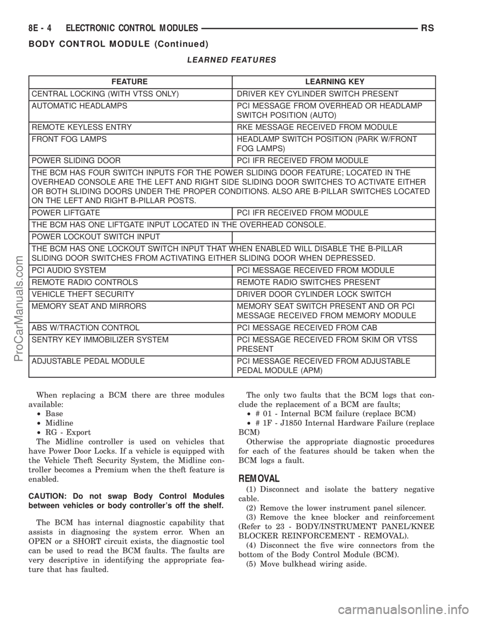
LEARNED FEATURES
FEATURE LEARNING KEY
CENTRAL LOCKING (WITH VTSS ONLY) DRIVER KEY CYLINDER SWITCH PRESENT
AUTOMATIC HEADLAMPS PCI MESSAGE FROM OVERHEAD OR HEADLAMP
SWITCH POSITION (AUTO)
REMOTE KEYLESS ENTRY RKE MESSAGE RECEIVED FROM MODULE
FRONT FOG LAMPS HEADLAMP SWITCH POSITION (PARK W/FRONT
FOG LAMPS)
POWER SLIDING DOOR PCI IFR RECEIVED FROM MODULE
THE BCM HAS FOUR SWITCH INPUTS FOR THE POWER SLIDING DOOR FEATURE; LOCATED IN THE
OVERHEAD CONSOLE ARE THE LEFT AND RIGHT SIDE SLIDING DOOR SWITCHES TO ACTIVATE EITHER
OR BOTH SLIDING DOORS UNDER THE PROPER CONDITIONS. ALSO ARE B-PILLAR SWITCHES LOCATED
ON THE LEFT AND RIGHT B-PILLAR POSTS.
POWER LIFTGATE PCI IFR RECEIVED FROM MODULE
THE BCM HAS ONE LIFTGATE INPUT LOCATED IN THE OVERHEAD CONSOLE.
POWER LOCKOUT SWITCH INPUT
THE BCM HAS ONE LOCKOUT SWITCH INPUT THAT WHEN ENABLED WILL DISABLE THE B-PILLAR
SLIDING DOOR SWITCHES FROM ACTIVATING EITHER SLIDING DOOR WHEN DEPRESSED.
PCI AUDIO SYSTEM PCI MESSAGE RECEIVED FROM MODULE
REMOTE RADIO CONTROLS REMOTE RADIO SWITCHES PRESENT
VEHICLE THEFT SECURITY DRIVER DOOR CYLINDER LOCK SWITCH
MEMORY SEAT AND MIRRORS MEMORY SEAT SWITCH PRESENT AND OR PCI
MESSAGE RECEIVED FROM MEMORY MODULE
ABS W/TRACTION CONTROL PCI MESSAGE RECEIVED FROM CAB
SENTRY KEY IMMOBILIZER SYSTEM PCI MESSAGE RECEIVED FROM SKIM OR VTSS
PRESENT
ADJUSTABLE PEDAL MODULE PCI MESSAGE RECEIVED FROM ADJUSTABLE
PEDAL MODULE (APM)
When replacing a BCM there are three modules
available:
²Base
²Midline
²RG - Export
The Midline controller is used on vehicles that
have Power Door Locks. If a vehicle is equipped with
the Vehicle Theft Security System, the Midline con-
troller becomes a Premium when the theft feature is
enabled.
CAUTION: Do not swap Body Control Modules
between vehicles or body controller's off the shelf.
The BCM has internal diagnostic capability that
assists in diagnosing the system error. When an
OPEN or a SHORT circuit exists, the diagnostic tool
can be used to read the BCM faults. The faults are
very descriptive in identifying the appropriate fea-
ture that has faulted.The only two faults that the BCM logs that con-
clude the replacement of a BCM are faults;
²# 01 - Internal BCM failure (replace BCM)
²# 1F - J1850 Internal Hardware Failure (replace
BCM)
Otherwise the appropriate diagnostic procedures
for each of the features should be taken when the
BCM logs a fault.
REMOVAL
(1) Disconnect and isolate the battery negative
cable.
(2) Remove the lower instrument panel silencer.
(3) Remove the knee blocker and reinforcement
(Refer to 23 - BODY/INSTRUMENT PANEL/KNEE
BLOCKER REINFORCEMENT - REMOVAL).
(4) Disconnect the five wire connectors from the
bottom of the Body Control Module (BCM).
(5) Move bulkhead wiring aside.
8E - 4 ELECTRONIC CONTROL MODULESRS
BODY CONTROL MODULE (Continued)
ProCarManuals.com
Page 370 of 2177
(3) Perform a visual inspection of the starter/
starter solenoid for corrosion, loose connections or
faulty wiring.
(4) Locate and remove the starter relay from the
Power Distribution Center (PDC). Refer to the PDC
label for relay identification and location.
(5) Connect a remote starter switch or a jumper
wire between the remote battery positive post and
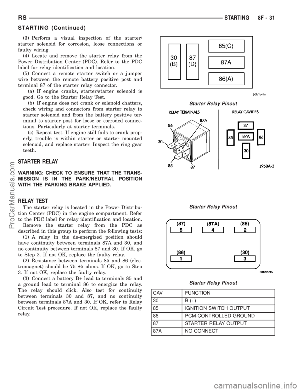
terminal 87 of the starter relay connector.
(a) If engine cranks, starter/starter solenoid is
good. Go to the Starter Relay Test.
(b) If engine does not crank or solenoid chatters,
check wiring and connectors from starter relay to
starter solenoid and from the battery positive ter-
minal to starter post for loose or corroded connec-
tions. Particularly at starter terminals.
(c) Repeat test. If engine still fails to crank prop-
erly, trouble is within starter or starter mounted
solenoid, and replace starter. Inspect the ring gear
teeth.
STARTER RELAY
WARNING: CHECK TO ENSURE THAT THE TRANS-
MISSION IS IN THE PARK/NEUTRAL POSITION
WITH THE PARKING BRAKE APPLIED.
RELAY TEST
The starter relay is located in the Power Distribu-
tion Center (PDC) in the engine compartment. Refer
to the PDC label for relay identification and location.
Remove the starter relay from the PDC as
described in this group to perform the following tests:
(1) A relay in the de-energized position should
have continuity between terminals 87A and 30, and
no continuity between terminals 87 and 30. If OK, go
to Step 2. If not OK, replace the faulty relay.
(2) Resistance between terminals 85 and 86 (elec-
tromagnet) should be 75 5 ohms. If OK, go to Step
3. If not OK, replace the faulty relay.
(3) Connect a battery B+ lead to terminals 85 and
a ground lead to terminal 86 to energize the relay.
The relay should click. Also test for continuity
between terminals 30 and 87, and no continuity
between terminals 87A and 30. If OK, refer to Relay
Circuit Test procedure. If not OK, replace the faulty
relay.
CAV FUNCTION
30 B (+)
85 IGNITION SWITCH OUTPUT
86 PCM-CONTROLLED GROUND
87 STARTER RELAY OUTPUT
87A NO CONNECT
Starter Relay Pinout
Starter Relay Pinout
Starter Relay Pinout
RSSTARTING8F-31
STARTING (Continued)
ProCarManuals.com
Page 449 of 2177
US/Mpush button to step through the zone numbers,
until the zone number for your geographic location
appears in the display.
(6) On Electronic Vehicle Information Center
(EVIC) and Compass Mini-Trip Computer (CMTC)
equipped vehicles momentarily depress and release
theRESETpush button to enter the displayed zone
number into the EVIC/CMTC module memory. On
Compass Temperature Module (CT) equipped vehicles
depress theC/Tpush button to enter the displayed
zone number into the electronic module memory.
(7) Confirm that the correct directions are now
indicated by the compass.
REMOVAL - OVERHEAD CONSOLE
(1) Disconnect and isolate the remote negative bat-
tery cable.
(2) Remove the overhead console retaining screw,
located in the front of console.
(3) Using your fingertips, grasp the sides of the
overhead console and pull straight down evenly to
disengage the two snap clips at the rear of the unit.
(4) Lower the overhead console far enough to
access the wire harness connectors.
(5) Disconnect the EVIC, CMTC or CT electronic
module and the reading/courtesy lamps electrical
connector.
(6) Remove the overhead console from the vehicle.
INSTALLATION
(1) Position the overhead console in the vehicle.
(2) Connect the EVIC, CMTC or CT electronic
module and the reading/courtesy lamps electrical
connector.
(3) Using your fingertips, grasp the sides of the
overhead console and push straight up evenly to
engage the two snap clips at the rear of the unit.
CAUTION: DO NOT PRESS ON THE SUNGLASS
STORAGE BIN DOOR. DAMAGE TO THE DOOR MAY
RESULT.
(4) Install the overhead console retaining screw,
located in the front of console. Torque the screw to
1.2 N´m (10 in. lbs.).
(5) Connect the remote negative battery cable.
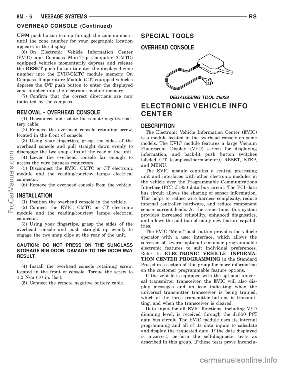
SPECIAL TOOLS
OVERHEAD CONSOLE
ELECTRONIC VEHICLE INFO
CENTER
DESCRIPTION
The Electronic Vehicle Information Center (EVIC)
is a module located in the overhead console on some
models. The EVIC module features a large Vacuum
Fluorescent Display (VFD) screen for displaying
information, and back-lit push button switches
labeled C/T (compass/thermometer), RESET, STEP,
and MENU.
The EVIC module contains a central processing
unit and interfaces with other electronic modules in
the vehicle over the Programmable Communications
Interface (PCI) J1850 data bus circuit. The PCI data
bus circuit allows the sharing of sensor information.
This helps to reduce wire harness complexity, reduce
internal controller hardware, and reduce component
sensor current loads. At the same time, this system
provides increased reliability, enhanced diagnostics,
and allows the addition of many new feature capabil-
ities.
The EVIC ªMenuº push button provides the vehicle
operator with a user interface, which allows the
selection of several optional customer programmable
electronic features to suit individual preferences.
Refer toELECTRONIC VEHICLE INFORMA-
TION CENTER PROGRAMMINGin the Standard
Procedures section of this group for more information
on the customer programmable feature options.
If the vehicle is equipped with the optional univer-
sal transmitter transceiver, the EVIC will also dis-
play messages and an icon indicating when the
universal transmitter transceiver is being trained,
which of the three transmitter buttons is transmit-
ting, and when the transceiver is cleared.
Data input for all EVIC functions, including VFD
dimming level, is received through the J1850 PCI
data bus circuit. The EVIC module uses its internal
programming and all of its data inputs to calculate
and display the requested data. If the data displayed
is incorrect, perform the self-diagnostic tests as
described in this group. If these tests prove inconclu-
DEGAUSSING TOOL #6029
8M - 6 MESSAGE SYSTEMSRS
OVERHEAD CONSOLE (Continued)
ProCarManuals.com