service reset CHRYSLER CARAVAN 2003 Service Manual
[x] Cancel search | Manufacturer: CHRYSLER, Model Year: 2003, Model line: CARAVAN, Model: CHRYSLER CARAVAN 2003Pages: 2177, PDF Size: 59.81 MB
Page 307 of 2177
grid can be repaired using a Mopar Rear Window
Defogger Repair Kit (Part Number 4267922) or
equivalent. (Refer to 8 - ELECTRICAL/HEATED
GLASS/WINDSHIELD GRID - STANDARD PROCE-
DURE).
RADIO
DESCRIPTION
Available factory-installed radio receivers for this
model include:
²AM/FM/cassette/CD (RAZ sales code)
²AM/FM/CD with CD changer control (RBK sales
code)
²AM/FM/cassette with CD changer control fea-
ture (RBB sales code)
²AM/FM/cassette/CD with rear audio (RBU sales
code)
All factory-installed radio receivers can communi-
cate on the Programmable Communications Interface
(PCI) data bus network. All factory-installed receiv-
ers are stereo Electronically Tuned Radios (ETR) and
include an electronic digital clock function.
These radio receivers can only be serviced by an
authorized radio repair station. See the latest War-
ranty Policies and Procedures manual for a current
listing of authorized radio repair stations.
OPERATION
The radio receiver operates on ignition switched
battery current that is available only when the igni-
tion switch is in the On or Accessory/Accessory Delay
positions. The electronic digital clock function of the
radio operates on fused battery current supplied
through the IOD fuse, regardless of the ignition
switch position.
For more information on the features, setting pro-
cedures, and control functions for each of the avail-
able factory-installed radio receivers, refer to the
owner's manual. For complete circuit diagrams, refer
to the appropriate wiring information. The wiring
information includes wiring diagrams, proper wire
and connector repair procedures, details of wire har-
ness routing and retention, connector pin-out infor-
mation and location views for the various wire
harness connectors, splices and grounds.
DIAGNOSIS AND TESTING - RADIO
WARNING: ON VEHICLES EQUIPPED WITH AIR-
BAGS, REFER TO ELECTRICAL, RESTRAINTS
BEFORE ATTEMPTING ANY STEERING WHEEL,
STEERING COLUMN, OR INSTRUMENT PANEL
COMPONENT DIAGNOSIS OR SERVICE. FAILURE
TO TAKE THE PROPER PRECAUTIONS COULDRESULT IN ACCIDENTAL AIRBAG DEPLOYMENT
AND POSSIBLE PERSONAL INJURY.
Any diagnosis of the Audio system should
begin with the use of the DRB IIItdiagnostic
tool. For information on the use of the DRB
IIIt, refer to the appropriate Diagnostic Service
Manual.
Refer to the appropriate wiring information. The
wiring information includes wiring diagrams, proper
wire and connector repair procedures, details of wire
harness routing and retention, connector pin-out
information and location views for the various wire
harness connectors, splices and grounds.
If the vehicle is equipped with remote radio
switches located on the back of the steering wheel
spokes, and the problem being diagnosed is related to
one of the symptoms listed below, be certain to check
the remote radio switches and circuits as described
in this group, prior to attempting radio diagnosis or
repair.
²Stations changing with no remote radio switch
input
²Radio memory presets not working properly
²Volume changes with no remote radio switch
input
²Remote radio switch buttons taking on other
functions
²CD player skipping tracks
²Remote radio switch inoperative.
CAUTION: The speaker output of the radio is a
ªfloating groundº system. Do not allow any speaker
lead to short to ground, as damage to the radio
may result.
(1) Check the fuse(s) in the junction block and the
Integrated Power Module (IPM). If OK, go to Step 2.
If not OK, repair the shorted circuit or component as
required and replace the faulty fuse(s).
(2) Check for battery voltage at the fuse in the
(IPM). If OK, go to Step 3. If not OK, repair the open
circuit to the battery as required.
(3) Turn the ignition switch to the ON position.
Check for battery voltage at the fuse in the junction
block. If OK, go to Step 4. If not OK, repair the open
circuit to the ignition switch as required.
(4) Turn the ignition switch to the OFF position.
Remove the radio, but do not unplug the wire har-
ness connectors. Check for continuity between the
radio chassis and a good ground. There should be
continuity. If OK, go to Step 5. If not OK, repair the
open radio chassis ground circuit as required.
(5) Connect the battery negative cable. Turn the
ignition switch to the ON position. Check for battery
voltage at the fused ignition switch output circuit
cavity of the radio wire harness connector. If OK, go
8A - 10 AUDIORS
QUARTER GLASS INTEGRAL ANTENNA - EXPORT (Continued)
ProCarManuals.com
Page 309 of 2177
motors, and fuel pumps that have been found to be
potential sources of RFI or EMI.
OPERATION
There are two common strategies that can be used
to suppress Radio Frequency Interference (RFI) and
ElectroMagnetic Interference (EMI) radio noise. The
first suppression strategy involves preventing the
production of RFI and EMI electromagnetic signals
at their sources. The second suppression strategy
involves preventing the reception of RFI and EMI
electromagnetic signals by the audio system compo-
nents.
The use of braided ground straps in key locations
is part of the RFI and EMI prevention strategy.
These ground straps ensure adequate ground paths,
particularly for high current components such as
many of those found in the starting, charging, igni-
tion, engine control and transmission control sys-
tems. An insufficient ground path for any of these
high current components may result in radio noise
caused by induced voltages created as the high cur-
rent seeks alternative ground paths through compo-
nents or circuits intended for use by, or in close
proximity to the audio system components or circuits.
Preventing the reception of RFI and EMI is accom-
plished by ensuring that the audio system compo-
nents are correctly installed in the vehicle. Loose,
corroded or improperly soldered wire harness connec-
tions, improperly routed wiring and inadequate audio
system component grounding can all contribute to
the reception of RFI and EMI. A properly grounded
antenna body and radio chassis, as well as a shielded
antenna coaxial cable with clean and tight connec-
tions will each help reduce the potential for reception
of RFI and EMI.
REMOTE SWITCHES
DESCRIPTION
A remote radio control switch option is available on
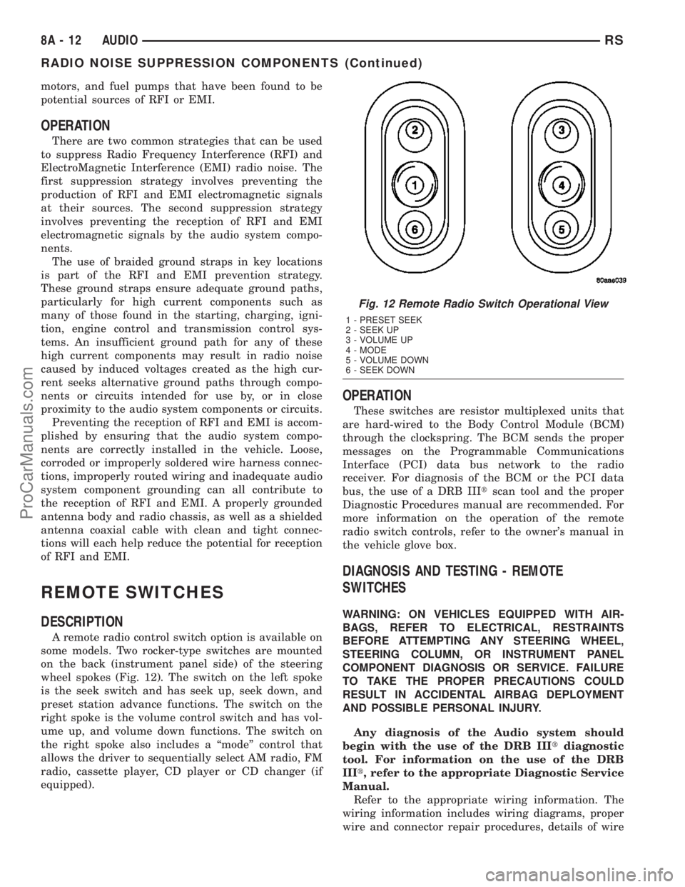
some models. Two rocker-type switches are mounted
on the back (instrument panel side) of the steering
wheel spokes (Fig. 12). The switch on the left spoke
is the seek switch and has seek up, seek down, and
preset station advance functions. The switch on the
right spoke is the volume control switch and has vol-
ume up, and volume down functions. The switch on
the right spoke also includes a ªmodeº control that
allows the driver to sequentially select AM radio, FM
radio, cassette player, CD player or CD changer (if
equipped).
OPERATION
These switches are resistor multiplexed units that
are hard-wired to the Body Control Module (BCM)
through the clockspring. The BCM sends the proper
messages on the Programmable Communications
Interface (PCI) data bus network to the radio
receiver. For diagnosis of the BCM or the PCI data
bus, the use of a DRB IIItscan tool and the proper
Diagnostic Procedures manual are recommended. For
more information on the operation of the remote
radio switch controls, refer to the owner's manual in
the vehicle glove box.
DIAGNOSIS AND TESTING - REMOTE
SWITCHES
WARNING: ON VEHICLES EQUIPPED WITH AIR-
BAGS, REFER TO ELECTRICAL, RESTRAINTS
BEFORE ATTEMPTING ANY STEERING WHEEL,
STEERING COLUMN, OR INSTRUMENT PANEL
COMPONENT DIAGNOSIS OR SERVICE. FAILURE
TO TAKE THE PROPER PRECAUTIONS COULD
RESULT IN ACCIDENTAL AIRBAG DEPLOYMENT
AND POSSIBLE PERSONAL INJURY.
Any diagnosis of the Audio system should
begin with the use of the DRB IIItdiagnostic
tool. For information on the use of the DRB
IIIt, refer to the appropriate Diagnostic Service
Manual.
Refer to the appropriate wiring information. The
wiring information includes wiring diagrams, proper
wire and connector repair procedures, details of wire
Fig. 12 Remote Radio Switch Operational View
1 - PRESET SEEK
2 - SEEK UP
3 - VOLUME UP
4 - MODE
5 - VOLUME DOWN
6 - SEEK DOWN
8A - 12 AUDIORS
RADIO NOISE SUPPRESSION COMPONENTS (Continued)
ProCarManuals.com
Page 445 of 2177
also affect compass operation. If the vehicle roof
should become magnetized, the demagnetizing and
calibration procedures found in this section may be
required to restore proper compass operation.
DESCRIPTION - TEMPERATURE
All the available overhead consoles on this model
include Temperature information. The temperature
displays the outside ambient temperature in whole
degrees. The temperature display can be toggled
from Fahrenheit to Celsius by selecting the desired
U.S./Metric option from the customer programmable
features. The displayed temperature is not an instant
reading of conditions, but an average temperature. It
may take the temperature display several minutes to
respond to a major temperature change, such as driv-
ing out of a heated garage into winter temperatures.
When the ignition switch is turned to the Off posi-
tion, the last displayed temperature reading stays in
the electronic control modules (CT, CMTC, EVIC)
memory. When the ignition switch is turned to the
On position again, the electronic module will display
the memory temperature for one minute; then update
the display to the current average temperature read-
ing within five minutes.
The temperature function is supported by an ambi-
ent temperature sensor. The sensor is mounted out-
side the passenger compartment near the front and
center of the vehicle, and is hard wired to the Front
Control Module (FCM). The FCM sends temperature
status messages to the module over the J1850 PCI
data bus circuit.
Following are general descriptions of the major
components used in the overhead console. Refer to
Wiring Diagrams for complete circuit schematics.
OPERATION
Refer to the vehicle Owner's Manual for specific
operation of each overhead console and its systems.
DIAGNOSIS AND TESTING - OVERHEAD
CONSOLE
If the problem with the overhead console is an
inaccurate or scrambled display, refer toSelf-Diag-
nostic Testbelow. If the problem with the overhead
console is incorrect Vacuum Fluorescent Display
(VFD) dimming levels, use a DRB IIItscan tool and
the proper Diagnostic Procedures manual to test for
the correct dimming message inputs being received
from the Body Control Module (BCM) or Front Con-
trol Module (FCM) over the J1850 Programmable
Communications Interface (PCI) data bus circuit. If
the problem is a no-display condition, use the follow-
ing procedures. For complete circuit diagrams, refer
toOverhead Consolein the Wiring Diagrams sec-
tion of the service manual.(1) Check the fused B(+) fuse in the integrated
power module. If OK, go to Step 2. If not OK, repair
the shorted circuit or component as required and
replace the faulty fuse.
(2) Check for battery voltage at the fused B(+) fuse
in the integrated power module. If OK, go to Step 3.
If not OK, repair the open fused B(+) circuit to the
fused B(+) fuse in the integrated power module as
required.
(3) Check the fused ignition switch output (run/
start) fuse in the integrated power module. If OK, go
to Step 4. If not OK, repair the shorted circuit or
component as required and replace the faulty fuse.
(4) Turn the ignition switch to the On position.
Check for battery voltage at the fused ignition switch
output (run/start) fuse in the integrated power mod-
ule. If OK, go to Step 5. If not OK, repair the open
fused ignition switch output (run/start) circuit to the
ignition switch as required.
(5) Turn the ignition switch to the Off position.
Disconnect and isolate the battery negative cable.
Remove the overhead console. Check for continuity
between the ground circuit cavity of the roof wire
harness connector for the electronics module and a
good ground. There should be continuity. If OK, go to
Step 6. If not OK, repair the open ground circuit to
ground as required.
(6) Connect the battery negative cable. Check for
battery voltage at the fused B(+) circuit cavity of the
roof wire harness connector for the electronics mod-
ule. If OK, go to Step 7. If not OK, repair the open
fused B(+) circuit to the fused B(+) fuse in the inte-
grated power module as required.
(7)
Turn the ignition switch to the On position.
Check for battery voltage at the fused ignition switch
output (run/start) circuit cavity of the roof wire har-
ness connector for the electronics module. If OK, refer
toSelf-Diagnostic Test
later this group for further
diagnosis of the electronics module and the J1850
PCI data bus circuit. If not OK, repair the open fused
ignition switch output (run/start) circuit to the fuse
in the integrated power module as required.
SELF-DIAGNOSTIC TEST
A self-diagnostic test is used to determine that the
electronics module is operating properly, and that all
the J1850 PCI data bus messages are being received
for initial operation. Initiate the self-diagnostic test
as follows:
(1) With the ignition switch in the Off position, on
Electronic Vehicle Information Center (EVIC) and
Compass Mini-Trip Computer (CMTC) equipped vehi-
cles simultaneously depress and hold theSTEP and
the RESET buttons. On Compass Temperature
Module (CT) equipped vehicles depress theC/T and
the US/M push buttons.
8M - 2 MESSAGE SYSTEMSRS
OVERHEAD CONSOLE (Continued)
ProCarManuals.com
Page 446 of 2177
(2) Turn the ignition switch to the On position.
(3)
Following completion of these tests, the electron-
ics module will display one of the following messages:
a.Pass Self Test (EVIC only), PASS (CT,
CMTC)- The electronics module is working properly.
b.Failed Self Test (EVIC only), FAIL (CT,
CMTC)- The electronics module has an internal fail-
ure. The electronics module is faulty and must be
replaced.
c.Failed J1850 Communication (EVIC only),
BUS (CT, CMTC)- The electronics module is not
receiving proper message input through the J1850
PCI data bus circuit. This can result from one or
more faulty electronic modules in the vehicle, or from
a faulty PCI data bus. The use of a DRB IIItscan
tool and the proper Diagnostic Procedures manual
are required for further diagnosis.
NOTE: If the compass functions, but accuracy is
suspect, it may be necessary to perform a variation
adjustment. This procedure allows the compass
unit to accommodate variations in the earth's mag-
netic field strength, based on geographic location.
Refer to Compass Variation Adjustment in the Stan-
dard Procedures section of this group.
NOTE: If the compass reading displays dashes, and
only ªCALº appears in the display, demagnetizing
may be necessary to remove excessive residual
magnetic fields from the vehicle. Refer to Compass
Demagnetizing in the Standard Procedures section
of this group.
STANDARD PROCEDURE
STANDARD PROCEDURE - READING/
COURTESY LAMP REPLACEMENT
(1) Open hood, disconnect and isolate the negative
battery cable remote terminal from the remote bat-
tery post.
(2) Remove the reading/courtesy lamp lens. Using
a trim stick, gently pry the forward edge of the read-
ing/courtesy lamp lens outward.
(3) Remove the reading/courtesy lamp socket from
the overhead console. Rotate the reading/courtesy
lamp socket one quarter turn counter clockwise.
(4) Remove the lamp and socket assembly.
(5) Reverse the above procedure to install.
STANDARD PROCEDURE - MODULE LAMP
REPLACEMENT
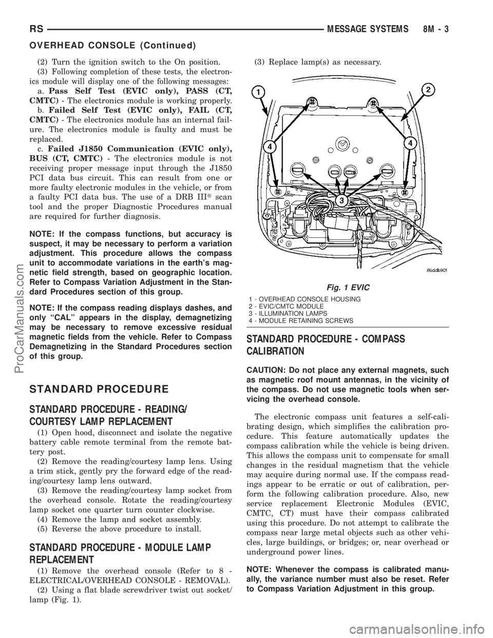
(1) Remove the overhead console (Refer to 8 -
ELECTRICAL/OVERHEAD CONSOLE - REMOVAL).
(2) Using a flat blade screwdriver twist out socket/
lamp (Fig. 1).(3) Replace lamp(s) as necessary.
STANDARD PROCEDURE - COMPASS
CALIBRATION
CAUTION: Do not place any external magnets, such
as magnetic roof mount antennas, in the vicinity of
the compass. Do not use magnetic tools when ser-
vicing the overhead console.
The electronic compass unit features a self-cali-
brating design, which simplifies the calibration pro-
cedure. This feature automatically updates the
compass calibration while the vehicle is being driven.
This allows the compass unit to compensate for small
changes in the residual magnetism that the vehicle
may acquire during normal use. If the compass read-
ings appear to be erratic or out of calibration, per-
form the following calibration procedure. Also, new
service replacement Electronic Modules (EVIC,
CMTC, CT) must have their compass calibrated
using this procedure. Do not attempt to calibrate the
compass near large metal objects such as other vehi-
cles, large buildings, or bridges; or, near overhead or
underground power lines.
NOTE: Whenever the compass is calibrated manu-
ally, the variance number must also be reset. Refer
to Compass Variation Adjustment in this group.
Fig. 1 EVIC
1 - OVERHEAD CONSOLE HOUSING
2 - EVIC/CMTC MODULE
3 - ILLUMINATION LAMPS
4 - MODULE RETAINING SCREWS
RSMESSAGE SYSTEMS8M-3
OVERHEAD CONSOLE (Continued)
ProCarManuals.com
Page 450 of 2177
sive, the use of a DRBIIItscan tool and the proper
Diagnostic Procedures manual are recommended for
further testing of the EVIC module and the J1850
PCI data bus circuit.
The EVIC module cannot be repaired, and is avail-
able for service only as a unit. This unit includes the
plastic module and display lens. If any of these com-
ponents is faulty or damaged, the complete EVIC
module must be replaced.
OPERATION
The EVIC has access to both non-switched and
ignition switched sources of battery current so that
some of its features remain operational at any time,
while others may only operate with the ignition
switch in the On position. When the ignition switch
is turned to the On position, the EVIC module VFD
will return to the last function being displayed before
the ignition was turned to the Off position.
The compass/thermometer display is the normal
EVIC display. With the ignition switch in the On
position, momentarily depressing and releasing the
C/T (compass/thermometer) push button switch will
cause the EVIC to return to the compass/thermome-
ter/trip computer display mode from any other mode.
While in the compass/thermometer/trip computer dis-
play mode, momentarily depressing and releasing the
Step push button will step through the available trip
computer display options.
The EVIC trip computer features several functions
that can be reset. The functions that can be reset
are: average fuel economy, trip odometer and elapsed
time. With the ignition switch in the On position and
with one of the functions of the trip computer that
can be reset currently displayed, depressing the
Reset push button twice within three seconds will
perform a global reset, and all of the trip computer
information that can be reset will be reset to zero.
With the ignition switch in the On position and the
function that is to be reset currently displayed,
momentarily depressing and releasing the Reset
push button once will perform a local reset, and only
the value of the displayed function will be reset to
zero. A global or local reset will only occur if the
function currently displayed is a function that can be
reset. The distance to service function can also be
reset using the local reset method, but it will reset
back to the Service Interval distance that is set in
the EVIC programmable features mode. Refer to
ELECTRONIC VEHICLE INFORMATION CEN-
TER PROGRAMMINGin the Standard Procedures
section of this group for more information on setting
the Service Interval.
For more information on the features, control func-
tions and setting procedures for the EVIC module,
see the owner's manual in the vehicle glove box.
DIAGNOSIS AND TESTING - ELECTRONIC
VEHICLE INFORMATION CENTER
Electronic Vehicle Information Center (EVIC) data
is obtained from the Body Control Module (BCM) on
the J1850 Data Bus circuit. The EVIC will display
dashes (- -) for any of the screens it did not receive
the bus messages. The label corresponding to the
missing information will be lit. If no EVIC data is
displayed, check the J1850 Data Bus circuit commu-
nications and the BCM. If the brightness level is
improper check the J1850 Data Bus circuit.
The DRB IIItis recommended for checking the
J1850 Data Bus circuit and the BCM. Perform the
EVIC self diagnosis before replacing the EVIC mod-
ule.
STANDARD PROCEDURE - ELECTRONIC
VEHICLE INFORMATION CENTER
PROGRAMMING
EVIC PROGRAMMING MODE
Some vehicles are equipped with a Electronic Vehi-
cle Information Center (EVIC) equipped overhead
console. The Electronic Vehicle Information Center
(EVIC) provides the vehicle operator with a user
interface, which allows the selection of several
optional customer programmable electronic features
to suit individual preferences. The EVIC must be
placed into its programming mode in order to view or
change the programmable features. To enter the
EVIC programming mode and to view or change the
selected programmable features options, proceed as
follows:
(1) Turn the ignition switch to the On position.
(2) Depress and release the Menu push button.
The first item in the programmable features menu
list will appear in the EVIC display.
(3) Momentarily depress and release the Menu
push button to step through the programmable fea-
tures list. Each programmable feature and its cur-
rently selected option will appear on the EVIC
display in the sequence shown in the Programmable
Features list that follows.
(4) Momentarily depress and release the Step push
button to step through the available options for the
programmable feature being displayed.
(5) The option that last appears in the display
with a programmable feature before exiting the pro-
gramming mode, becomes the newly selected pro-
grammable feature option.
(6) The EVIC exits the programming mode and
returns to its normal operating mode when the C/T
push button is depressed or when the end of the pro-
grammable features menu list is reached, whichever
occurs first.
RSMESSAGE SYSTEMS8M-7
ELECTRONIC VEHICLE INFO CENTER (Continued)
ProCarManuals.com
Page 451 of 2177
PROGRAMMABLE FEATURES
NOTE: Tire pressure monitoring (TPM) system infor-
mation is not covered in this section of the service
manual. Refer to the tires/wheels section of this
manual for detailed tire pressure monitoring system
information.
²LANGUAGE?- The options include English,
Francaise, Deutsch, Italiana, or Espanol. The default
is English. All EVIC display nomenclature, including
the trip computer functions, warning messages and
the programmable features appear in the selected
language.
²DISPLAY U.S. OR METRIC?- The options
include U.S. and M. The default is U.S. This feature
toggles the trip computer temperature, fuel economy
and odometer display readings between U.S. and
metric units of measure. It also changes the odome-
ter display in the instrument cluster.
²SERVICE INTV. =- The options include from
1000 to 12000 kilometers in 1000 kilometer incre-
ments (2000 to 7500 miles in 500 mile increments).
The default is 12000 kilometers (7500 miles). The
selected distance becomes the interval at which the
Perform Service warning message will be displayed
by the EVIC. If a new distance is selected, a second
programmable feature appears,RESET SERVICE
DISTANCE?- The options include No and Yes. The
default is Yes. When Yes is selected, the accumulated
distance since the last previous Perform Service
warning message will be reset to zero because the
service interval has been changed. When No is
selected, the distance until the next Perform Service
warning message is reduced by the accumulated dis-
tance since the last previous message.
²USE FACTORY SETTINGS?- The options
include Yes and No. The default is Yes. When yes is
selected all the programmable features will return to
there defaults and the rest of the programmable fea-
tures will not be displayed. If No is selected the rest
of the programmable features will be displayed at
there default values. This feature will automatically
return to the Yes default under two conditions. First,
if no programmable features are changed from there
defaults. Second, if all the programmable features
equal there defaults.
²AUTO DOOR LOCKS?- The options include
Yes and No. The default is Yes. When Yes is selected,
all doors and the liftgate lock automatically when
vehicle speed reaches 25 kilometers-per-hour (15
miles-per-hour). If YES is selected, a second program-
mable feature appears,AUTO UNLOCK ON EXIT?
- The options again include Yes and No. The default
is No. When Yes is selected, following each Auto Door
Lock event all doors and the liftgate will automati-
cally unlock when the driver door is opened, if thevehicle is stopped and the transmission gear selector
is in Park or Neutral. The Auto Door Unlock event
will only occur once following each Auto Door Lock
event.
²REMOTE UNLOCK- The options include
Driver Door 1st and All Doors. The default is Driver
Door 1st. When Diver Door 1st is selected, only the
driver door unlocks when the Unlock button of the
Remote Keyless Entry (RKE) transmitter is
depressed once. The Unlock button of the RKE trans-
mitter must be depressed twice to unlock all doors.
When All Doors is selected, all doors unlock when the
Unlock button of the RKE transmitter is depressed
once.
²REMOTE LINKED TO MEMORY?- This pro-
grammable feature only applies to vehicles equipped
with the optional memory / heated system. The
options include Yes and No. The default is No. When
Yes is selected, the memory system will recall the
Driver 1 or Driver 2 memory settings assigned to the
RKE transmitter being used to unlock the vehicle.
When No is selected, the memory system will only
recall memory settings when the Driver 1 or Driver 2
push buttons of the memory switch on the driver side
front door trim panel are depressed.
²SOUND HORN ON LOCK?- The options
include Yes and No. The default is No. When Yes is
selected, a short horn chirp will provide an audible
confirmation when the RKE receiver recognizes a
valid Lock signal from an RKE transmitter. When No
is selected, no horn chirp will occur with the RKE
Lock event. This feature may be selected indepen-
dent of theFLASH LIGHTS WITH LOCKS?pro-
grammable feature.
²FLASH LIGHTS WITH LOCKS?- The options
include Yes and No. The default is Yes. When Yes is
selected, a single flash of the hazard warning lamps
will provide an optical confirmation when the RKE
receiver recognizes a valid Lock signal from an RKE
transmitter, and two flashes of the same lamps will
occur when the RKE receiver recognizes a valid
Unlock signal from an RKE transmitter. When No is
selected, no lamp flash will occur with the RKE Lock
or Unlock event. This feature may be selected inde-
pendent of theSOUND HORN ON LOCK?pro-
grammable feature.
²HEADLAMP DELAY =- The options include
Off, 30 Sec, 60 Sec, and 90 Sec. The default is 90 Sec.
When a time interval is selected, the headlamps will
remain on for that length of time when the head-
lamps are turned off after the ignition is turned off,
or if the Auto mode is selected on vehicles with the
Auto Headlamps option. When Off is selected, the
headlamp delay feature is disabled.
²HEADLAMPS ON WITH WIPERS?- This pro-
grammable feature only applies to vehicles equipped
8M - 8 MESSAGE SYSTEMSRS
ELECTRONIC VEHICLE INFO CENTER (Continued)
ProCarManuals.com
Page 480 of 2177
CONDITION POSSIBLE CAUSES CORRECTION
Power loss during power
door operationWiring problems (system or
vehicle)Troubleshoot using electrical schematics.
Refer to wiring diagrams
Low battery voltage Charge battery
Failure of sliding door control or
body control moduleDisconnect then reconnect battery to reset
module, function door, if no function exists
check for loose wire connections, see Body
Diagnostic Manual for detailed procedures
Failure of drive assembly Remove lower drive unit and check for no
drive condition
No latching in primary
and/or secondary positionsFailure of inside/outside handle
assemblyGo to that9POSSIBLE CAUSE9and review
9CORRECTIONS9
Failure of latch assembly Check wire connections and for blown fuse
Check cable connections
Check for foreign matter preventing the
operation of latch assembly
Troubleshoot using body diagnostic manual
Replace latch assembly, if necessary
Binding or sticking of components Establish location of binding and replace
necessary components
Failure of sliding door control or
body control moduleDisconnect then reconnect battery to reset
module, function door, if no function exists
check for loose wire connections, see Body
Diagnostic Manual for detailed procedures
Door seal force too high Inspect seals for damage, mis-assembly,
foreign matter. Refer to Door adjustment in
the Body section of the service manual for
specifications
Failure of drive assembly Remove lower drive unit and check for no
drive condition
Failure of striker Striker misaligned or loose
Striker damaged
Replace striker if necessary
Latch will not fully release
from primary positionFailure of latch assembly Check wire connections and for blown fuse
Check cable connections
Check for foreign matter preventing the
operation of latch assembly
Troubleshoot using body diagnostic manual
Replace latch assembly, if necessary
Failure of fuel filler door lockout
mechanismCheck operation of fuel filler door lockout
mechanism. Refer to the Body section for
information
RSPOWER SLIDING DOOR SYSTEM8N-25
POWER SLIDING DOOR SYSTEM (Continued)
ProCarManuals.com
Page 506 of 2177

The power seat system includes the following com-
ponents:
²Power seat recliners
²Power seat switches
²Power seat tracks
²Circuit breaker
The power seat system with memory and heated
seat options includes the following components:
²Power seat recliner
²Power seat switch
²Power seat track.
²Memory Seat Mirror Module (MSMM)
²Memory set switch
²Heated Seat Module (HSM)
²Heated seat switch
²Electronic Vehicle Information Center (EVIC)
²Programmable Communications Interface (PCI)
data bus network
Refer to Wiring Diagrams for complete circuit dia-
grams. Following are general descriptions and opera-
tions for the major components in the power seat
system and memory seat system.
DESCRIPTION - MEMORY SYSTEM
An electronic memory system is available on some
models. The memory system is able to store and
recall the driver side power seat positions (including
the power recliner position) and both outside side
view mirrors positions for two drivers. On vehicles
equipped with a factory radio, the memory system is
also able to store and recall radio station presets fortwo drivers. The memory system also will store and
recall the last station listened to for each driver, even
if it is not one of the preset stations.
The memory system will automatically return to
its preset settings when the corresponding numbered
button of the memory switch is depressed, or when
the doors are unlocked using the corresponding
Remote Keyless Entry (RKE) transmitter. A customer
programmable feature of the memory system allows
the RKE recall of memory features to be disabled, if
desired. This programmable feature is internal in the
EVIC module, which is located in the overhead con-
sole.
A Memory Seat Mirror Module (MSMM) is used on
some models to control and integrate the many elec-
tronic functions and features included in the memory
seat and mirror systems.
The memory system includes the following compo-
nents:
²Memory Seat Mirror Module (MSMM)
²Memory set switch
²Position potentiometers on both outside side
view mirrors
²Position potentiometers on the driver side power
seat track and power seat recliner motors.
²Electronic Vehicle Information Center (EVIC)
²Radio receiver (if PCI data bus capable).
Certain functions of the memory system rely upon
resources shared with other electronic modules in the
vehicle over the Programmable Communications
Interface (PCI) J1850 data bus network. The PCI
data bus network allows the sharing of sensor infor-
mation. This helps to reduce wire harness complexity,
internal controller hardware, and component sensor
current loads. At the same time, this system provides
increased reliability, enhanced diagnostics, and
allows the addition of many new feature capabilities.
Initial diagnosis of these electronic modules or the
PCI data bus network requires the use of a DRBIIIt
scan tool and the proper Diagnostic Procedures man-
ual. If this method does not prove conclusive, the use
of a automotive meter such as the Fluket, the proper
wiring schematics and the service manual diagnostic
routines are required.
The other electronic modules that may affect mem-
ory system operation are as follows:
²Body Control Module (BCM)- Refer toBody
Control Modulein Electronic Control Modules for
more information.
²Powertrain Control Module (PCM)- Refer to
Powertrain Control Modulein Electronic Control
Modules for more information.
²Transmission Control Module (TCM)- Refer
toTransmission Control Modulein Electronic
Control Modules for more information.
Fig. 1 Identifying a Side Airbag Equipped Seat
1 - Airbag Label
RSPOWER SEAT SYSTEM8N-51
POWER SEAT SYSTEM (Continued)
ProCarManuals.com
Page 513 of 2177

(3) Reconnect the power seat wire harness connec-
tor to the power seat switch connector receptacle.
(4) Position the outboard seat cushion side shield
onto the seat cushion frame
(5) Install and tighten the screws that secure the
outboard seat cushion side shield to the seat cushion
frame. Tighten the screws to 1.5 N´m (14 in. lbs.).
(6) Install the switch knobs on the switch control
levers, if equipped.
(7) Reconnect the battery negative cable.
DRIVER POWER SEAT TRACK
DESCRIPTION
The eight-way driver side power seat option
includes a electrically operated power seat track
located under the driver side front seat. The front
power seat track on the driver side of the vehicle also
provides the mounting location for the Memory Seat/
Mirror Module (MSMM). The power seat circuit
breakers are mounted on the rear of the driver side
power seat track, just behind the seat rear trim
panel. The lower half of the power seat track is
secured to the floor panel via four studs and nuts
that must be accessed from the underside of the vehi-
cle. Four bolts secure the bottom of the seat cushion
pan to the upper half of the power seat track unit.
Four additional bolts secure the seat back frame to
the power seat track unit.
The power seat track unit includes four reversible
electric motors that are secured to the upper half of
the track unit. Each motor moves the seat adjuster
through a combination of worm-drive gearboxes and
screw-type drive units. Each of the four power seat
track motors used on models equipped with the
optional memory system incorporates a position
potentiometer integral to the motor assembly, which
electronically monitors the motor position. This
enables the memory system to function by referenc-
ing the motor positions programmed into the memory
seat/mirror module.
The front and rear of the seat are operated by two
separate vertical adjustment motors. These motors
can be operated independently of each other, tilting
the entire seat assembly forward or rearward; or,
they can be operated in unison by selecting the
proper power seat switch functions, which will raise
or lower the entire seat assembly. A third motor is
the horizontal adjustment motor, which moves the
seat track in the forward and rearward directions.
The forth motor is the recliner adjustment motor,
which moves the seat back in the forward and rear-
ward directions.
The power seat track unit cannot be repaired, and
is serviced only as a complete unit. If any componentin this unit is faulty or damaged, the entire power
seat track unit must be replaced.
OPERATION
When the driver side power seat switch control
knob or knobs are actuated, a battery feed and a
ground path are applied through the switch contacts
to the power seat track or recliner adjuster motor.
The selected adjuster motor operates to move the
seat track or recliner through its drive unit in the
selected direction until the switch is released, or
until the travel limit of the adjuster is reached.
When the switch is moved in the opposite direction,
the battery feed and ground path to the motor are
reversed through the switch contacts. This causes the
adjuster motor to run in the opposite direction.
No power seat switch should be held applied in any
direction after the adjuster has reached its travel
limit. The power seat adjuster motors each contain a
self-resetting circuit breaker to protect them from
overload. However, consecutive or frequent resetting
of the circuit breaker must not be allowed to con-
tinue, or the motor may be damaged.
See the owner's manual in the vehicle glove box for
more information on the power seat switch functions
and the seat adjusting procedures.
DIAGNOSIS AND TESTING - DRIVER POWER
SEAT TRACK
WARNING: SOME VEHICLES ARE EQUIPPED WITH
SEATBACK MOUNTED AIRBAGS. BEFORE
ATTEMPTING TO DIAGNOSE OR SERVICE ANY
SEAT OR POWER SEAT SYSTEM COMPONENT
YOU MUST FIRST DISCONNECT AND ISOLATE THE
BATTERY NEGATIVE CABLE. THEN WAIT TWO MIN-
UTES FOR THE SYSTEM CAPACITOR TO DIS-
CHARGE BEFORE FURTHER SYSTEM SERVICE.
THIS IS THE ONLY SURE WAY TO DISABLE THE
AIRBAG SYSTEM. FAILURE TO DO SO COULD
RESULT IN ACCIDENTAL AIRBAG DEPLOYMENT
AND POSSIBLE PERSONAL INJURY.
Actuate the driver side power seat switch to move
all three power seat track adjusters in each direction.
The power seat track adjusters should move in each
of the selected directions. If a power seat track
adjuster fails to operate in only one direction, move
the adjuster a short distance in the opposite direction
and test again to be certain that the adjuster is not
at its travel limit. If the power seat track adjuster
still fails to operate in only one direction, refer to
Diagnosis and Testing Power Seat Switchin this
section. If the power seat track adjuster fails to oper-
ate in more than one direction, perform the following
tests. For complete circuit diagrams, refer toWiring
Diagrams.
8N - 58 POWER SEAT SYSTEMRS
PASSENGER SEAT SWITCH (Continued)
ProCarManuals.com
Page 515 of 2177

ward and rearward directions. The recliner adjust-
ment motor moves the seat back in the forward and
rearward directions.
The power seat track unit cannot be repaired, and
is serviced only as a complete unit. If any component
in this unit is faulty or damaged, the entire power
seat track unit must be replaced.
OPERATION
When a passenger side power seat switch control
knob or knobs are actuated, a battery feed and a
ground path are applied through the switch contacts
to the power seat track or recliner adjuster motor.
The selected adjuster motor operates to move the
seat track or recliner through its drive unit in the
selected direction until the switch is released, or
until the travel limit of the adjuster is reached.
When the switch is moved in the opposite direction,
the battery feed and ground path to the motor are
reversed through the switch contacts. This causes the
adjuster motor to run in the opposite direction.
No power seat switch should be held applied in any
direction after the adjuster has reached its travel
limit. The power seat adjuster motors each contain a
self-resetting circuit breaker to protect them from
overload. However, consecutive or frequent resetting
of the circuit breaker must not be allowed to con-
tinue, or the motor may be damaged.
See the owner's manual in the vehicle glove box for
more information on the power seat switch functions
and the seat adjusting procedures.
DIAGNOSIS AND TESTING - POWER SEAT
TRACK
WARNING: SOME VEHICLES ARE EQUIPPED WITH
SEATBACK MOUNTED AIRBAGS. BEFORE
ATTEMPTING TO DIAGNOSE OR SERVICE ANY
SEAT OR POWER SEAT SYSTEM COMPONENT
YOU MUST FIRST DISCONNECT AND ISOLATE THE
BATTERY NEGATIVE CABLE. THEN WAIT TWO MIN-
UTES FOR THE SYSTEM CAPACITOR TO DIS-
CHARGE BEFORE FURTHER SYSTEM SERVICE.
THIS IS THE ONLY SURE WAY TO DISABLE THE
AIRBAG SYSTEM. FAILURE TO DO SO COULDRESULT IN ACCIDENTAL AIRBAG DEPLOYMENT
AND POSSIBLE PERSONAL INJURY.
Actuate the passenger side power seat switch to
move the power seat track adjuster in each direction.
The power seat track adjuster should move in each of
the selected directions. If a power seat track adjuster
fails to operate in only one direction, move the
adjuster a short distance in the opposite direction
and test again to be certain that the adjuster is not
at its travel limit. If the power seat track adjuster
still fails to operate in only one direction, refer to
Diagnosis and Testing Power Seat Switchin this
section. If the power seat track adjuster fails to oper-
ate in more than one direction, perform the following
tests. For complete circuit diagrams, refer toWiring
Diagrams.
(1) Check the power seat circuit breaker under the
seat. If OK, go to Step 2. If not OK, replace the
faulty power seat circuit breaker.
(2) Check for battery voltage at the power seat cir-
cuit breaker under the seat. If OK, go to Step 3. If
not OK, repair the open fused B(+) circuit to the fuse
in the Intelligent Power Module as required.
(3) Remove the outboard seat cushion side shield
from the seat. Disconnect the seat wire harness con-
nector from the power seat switch connector recepta-
cle. Check for battery voltage at the fused B(+)
circuit cavity of the power seat wire harness connec-
tor for the power seat switch. If OK, go to Step 4. If
not OK, repair the open fused B(+) circuit to the
power seat circuit breaker under the seat as
required.
(4) Check for continuity between the ground cir-
cuit cavity of the power seat wire harness connector
for the power seat switch and a good ground. There
should be continuity. If OK, go to Step 5. If not OK,
repair the open ground circuit to ground as required.
(5) Test the power seat switch. Refer toDiagnosis
and Testing Power Seat Switchin this section. If
the switch tests OK, test the circuits of the power
seat wire harness between the inoperative power seat
track adjuster motor and the power seat switch for
shorts or opens. If the circuits check OK, replace the
faulty power seat track unit. If the circuits are not
OK, repair the power seat wire harness as required.
8N - 60 POWER SEAT SYSTEMRS
PASSENGER POWER SEAT TRACK (Continued)
ProCarManuals.com