ECU CHRYSLER CARAVAN 2005 Service Manual
[x] Cancel search | Manufacturer: CHRYSLER, Model Year: 2005, Model line: CARAVAN, Model: CHRYSLER CARAVAN 2005Pages: 2339, PDF Size: 59.69 MB
Page 1618 of 2339

(28) Obtain helper and/or transmission jack.
Secure transmission jack to transaxle assembly.
(29) Remove upper mount bracket from transaxle
(Fig. 14).
(30) Remove remaining transaxle bellhousing-to-
engine bolts.
(31) Remove transaxle assembly from vehicle.
DISASSEMBLY
NOTE: If transaxle is being overhauled (clutch
and/or seal replacement) or replaced, it is neces-
sary to perform the PCM/TCM Quick Learn Proce-
dure. (Refer to 8 - ELECTRICAL/ELECTRONIC
CONTROL MODULES/POWERTRAIN/TRANSMIS-
SION CONTROL MODULE - STANDARD PROCE-
DURE)
NOTE: This procedure does not include final drive
(differential) disassembly.
(1) Remove input and output speed sensors.
(2) Remove three (3) solenoid/pressure switch
assembly-to-case bolts.
(3) Remove solenoid/pressure switch assembly and
gasket (Fig. 15).(4) Remove oil pan-to-case bolts (Fig. 16).
(5) Remove oil pan (Fig. 17).
Fig. 15 Solenoid/Pressure Switch Assembly and
Gasket
1 - SOLENOID/PRESSURE SWITCH ASSEMBLY
2 - GASKET
Fig. 16 Remove Oil Pan Bolts
1 - OIL PAN BOLTS (USE RTV UNDER BOLT HEADS)
Fig. 17 Remove Oil Pan
1 - OIL PAN
2 - 1/8 INCH BEAD OF MOPARTATF RTV (MS-GF41)
3 - OIL FILTER
RS41TE AUTOMATIC TRANSAXLE21 - 157
41TE AUTOMATIC TRANSAXLE (Continued)
Page 1657 of 2339

(69) Install and tighten solenoid/pressure switch
assembly-to-transaxle case bolts to 12 N´m (110 in.
lbs.) (Fig. 158).
(70) Install and torque input and output speed
sensors to case to 27 N´m (20 ft. lbs.).
INSTALLATION
NOTE: If transaxle assembly has been replaced or
overhauled (clutch and/or seal replacement), it is
necessary to perfrom the ªQuick-Learnº procedure.
(Refer to 8 - ELECTRICAL/ELECTRONIC CONTROL
MODULES/TRANSMISSION CONTROL MODULE -
STANDARD PROCEDURE)
(1) Using a transmission jack and a helper, posi-
tion transaxle assembly to engine. Install and torque
bellhousing bolts to 95 N´m (70 ft. lbs.).
(2) Install upper mount assembly to transaxle and
torque bolts to 54 N´m (40 ft. lbs.) (Fig. 159).
(3) Raise engine/transaxle assembly into position.
Install and torque upper mount-to-bracket thru-bolt
to 75 N´m (55 ft. lbs.) (Fig. 159).
(4) Remove transmission jack and screw jack.
(5) Secure left wheelhouse splash shield.
(6) Install torque converter-to-drive plate bolts and
torque to 88 N´m (65 ft. lbs.)
(7) Install inspection cover.
(8) Install lateral bending brace.
(9) Install starter motor.
(10) Install front mount/bracket assembly.
(11) Align and install rear mount bracket-to-case
bolts by hand (Fig. 160). Torque horizontal bolt to
102 N´m (75 ft. lbs.).(12) AWD models: Install power transfer unit.
(Refer to 21 - TRANSMISSION/TRANSAXLE/
POWER TRANSFER UNIT - INSTALLATION)
(13) Install left and right halfshaft assemblies.
(Refer to 3 - DIFFERENTIAL & DRIVELINE/HALF
SHAFT - INSTALLATION)
(14) Install front wheel/tire assemblies.
(15) Lower vehicle.
(16) Torque remaining rear mount bracket-to-tran-
saxle vertical bolts (Fig. 160) to 102 N´m (75 ft. lbs.).
(17) Install transaxle upper bellhousing-to-block
bolts and torque to 95 N´m (70 ft. lbs.).
(18) Install and connect crank position sensor (if
equipped).
(19) Connect gearshift cable to upper mount
bracket and transaxle manual valve lever (Fig. 161).
(20) Connect solenoid/pressure switch assembly
(Fig. 162).
(21) Connect transmission range sensor connector
(Fig. 162).
(22) Connect input and output speed sensor con-
nectors (Fig. 162).
(23) Remove plugs and connect transaxle oil cooler
lines. (Refer to 7 - COOLING/TRANSMISSION -
STANDARD PROCEDURE)
(24) Remove plug and Install fluid level indicator/
tube assembly.
Fig. 158 Solenoid Pack-to-Transaxle Bolts
1 - BOLTS
2 - SOLENOID AND PRESSURE SWITCH ASSEMBLY
Fig. 159 Left Mount to Bracket and Transaxle
1 - BOLT - BRACKET TO FRAME RAIL 68 N´m (50 ft. lbs.)
2 - BOLT - MOUNT TO RAIL THRU 75 N´m (55 ft. lbs.)
3 - BOLT - LEFT MOUNT TO TRANSAXLE 54 N´m (40 ft. lbs.)
4 - TRANSAXLE
5 - MOUNT - LEFT
6 - BRACKET - LEFT MOUNT
21 - 196 41TE AUTOMATIC TRANSAXLERS
41TE AUTOMATIC TRANSAXLE (Continued)
Page 1695 of 2339

(9) Disconnect gear shift cable from gear shift
lever (Fig. 212).
(10) Remove gear shift cable from column bracket
(Fig. 212).
(11) Disengage grommet from dash panel (Fig.
213) and remove gear shift cable from inside vehicle.INSTALLATION
(1) Fish gear shift cable dash panel opening into
engine compartment and secure grommet (Fig. 214).
(2) Install gear shift cable through column bracket
(Fig. 215) until audible ªclickº is heard.
(3) Connect gear shift cable to gear shift lever (Fig.
215).
Fig. 212 Gearshift Cable at Column
1 - GEAR SHIFT CABLE
Fig. 213 Gearshift Cable/Grommet at Dash Panel
1 - CABLE GROMMET
2 - DASH PANEL
Fig. 214 Gearshift Cable/Grommet at Dash Panel
1 - CABLE GROMMET
2 - DASH PANEL
Fig. 215 Gearshift Cable at Column
1 - GEAR SHIFT CABLE
21 - 234 41TE AUTOMATIC TRANSAXLERS
GEAR SHIFT CABLE (Continued)
Page 1741 of 2339

ment can be obtained. The result of this engagement
is a direct 1:1 mechanical link between the engine
and the transmission.
The engagement and disengagement of the TCC
are automatic and controlled by the Powertrain Con-
trol Module (PCM). The engagement cannot be acti-
vated in the lower gears because it eliminates the
torque multiplication effect of the torque converter
necessary for acceleration. Inputs that determine
clutch engagement are: coolant temperature, vehicle
speed and throttle position. The torque converter
clutch is engaged by the clutch solenoid on the valve
body. The clutch will engage at approximately 56
km/h (35 mph) with light throttle, after the shift to
third gear.
REMOVAL
(1) Remove transmission and torque converter
from vehicle. (Refer to 21 - TRANSMISSION/TRANS-
AXLE/AUTOMATIC - 41TE - REMOVAL)
(2) Place a suitable drain pan under the converter
housing end of the transmission.
CAUTION: Verify that transmission is secure on the
lifting device or work surface, the center of gravity
of the transmission will shift when the torque con-
verter is removed creating an unstable condition.
The torque converter is a heavy unit. Use caution
when separating the torque converter from the
transmission.
(3) Pull the torque converter forward until the cen-
ter hub clears the oil pump seal.
(4) Separate the torque converter from the trans-
mission.
INSTALLATION
Check converter hub and drive notches for sharp
edges, burrs, scratches, or nicks. Polish the hub and
notches with 320/400 grit paper or crocus cloth if nec-
essary. The hub must be smooth to avoid damaging
the pump seal at installation.
(1) Lubricate converter hub and oil pump seal lip
with transmission fluid.
(2) Place torque converter in position on transmis-
sion.
CAUTION: Do not damage oil pump seal or bushing
while inserting torque converter into the front of the
transmission.(3) Align torque converter to oil pump seal open-
ing.
(4) Insert torque converter hub into oil pump.
(5) While pushing torque converter inward, rotate
converter until converter is fully seated in the oil
pump gears.
(6) Check converter seating with a scale and
straightedge (Fig. 329). Surface of converter lugs
should be 1/2 in. to rear of straightedge when con-
verter is fully seated.
(7) If necessary, temporarily secure converter with
C-clamp attached to the converter housing.
(8) Install the transmission in the vehicle. (Refer
to 21 - TRANSMISSION/TRANSAXLE/AUTOMATIC
- 41TE - INSTALLATION)
(9) Fill the transmission with the recommended
fluid. (Refer to 21 - TRANSMISSION/TRANSAXLE/
AUTOMATIC - 41TE/FLUID - STANDARD PROCE-
DURE)
Fig. 329 Checking Torque Converter Seating
1 - SCALE
2 - STRAIGHTEDGE
21 - 280 41TE AUTOMATIC TRANSAXLERS
TORQUE CONVERTER (Continued)
Page 1753 of 2339

(5) Install check balls into position as shown in
(Fig. 360). If necessary, secure them with petrolatum
or transmission assembly gel for assembly ease.
(6) Install thermal valve into transfer plate (Fig.
361).
Fig. 360 Ball Check Location
1 - (#4) BALL CHECK LOCATION
2 - (#2) BALL CHECK LOCATION
3 - RETAINER4 - (#3) BALL CHECK LOCATION
5 - LOW/REVERSE SWITCH VALVE
6 - T/C LIMIT VALVE
Fig. 361 Install Thermal Valve
1 - THERMAL VALVE
21 - 292 41TE AUTOMATIC TRANSAXLERS
VALVE BODY (Continued)
Page 1765 of 2339

REMOVAL
REMOVAL - TIRE AND WHEEL ASSEMBLY
(ALUMINUM WHEEL)
(1) Raise the vehicle so the tire and wheel assem-
bly clears ground level.
(2) Remove the 5 wheel mounting nuts from the
studs.
(3) Remove the tire and wheel from the hub.
REMOVAL - TIRE AND WHEEL ASSEMBLY
(STEEL WHEEL)
(1) Raise the vehicle so the tire and wheel assem-
bly clears ground level.
(2) Noting the location of the valve stem in rela-
tionship to the wheel mounting nuts, remove the
three wheel mounting nuts securing the wheel cover
to the wheel and hub (Fig. 12).
CAUTION: When removing the wheel cover, do not
pry the wheel cover from the wheel. This can result
in damage to the wheel cover. The wheel cover is
removed by pulling it off the wheel by hand.
(3) Grasp the wheel cover at the edges in line with
the remaining installed wheel mounting nuts and
pull straight outward from the wheel. This will pop
the wheel cover retaining tabs over the two remain-
ing wheel nuts, removing the wheel cover from the
vehicle.
(4) Remove the two remaining wheel mounting
nuts from the hub's studs.
(5) Remove the wheel and tire from the hub.
INSTALLATION
INSTALLATION - TIRE AND WHEEL ASSEMBLY
(ALUMINUM WHEEL)
NOTE: Never use oil or grease on studs or wheel
mounting nuts.
(1) Position the tire and wheel assembly on the
wheel mounting studs using the hub pilot as a guide.
Place and hold the wheel flush up against the mount-
ing surface.
(2) Loosely install all 5 wheel mounting nuts.
Lightly snug the wheel nuts, then progressively
tighten them in the proper sequence (Fig. 13).
Tighten wheel mounting nuts to 135 N´m (100 ft.
lbs.).
(3) Lower the vehicle.
INSTALLATION - TIRE AND WHEEL ASSEMBLY
(STEEL WHEEL)
NOTE: Never use oil or grease on studs or wheel
mounting nuts.
(1) Position the tire and wheel assembly on the
wheel mounting studs using the hub pilot as a guide.
Place and hold the wheel flush up against the mount-
ing surface.
NOTE: Wheel mounting nuts must be installed on
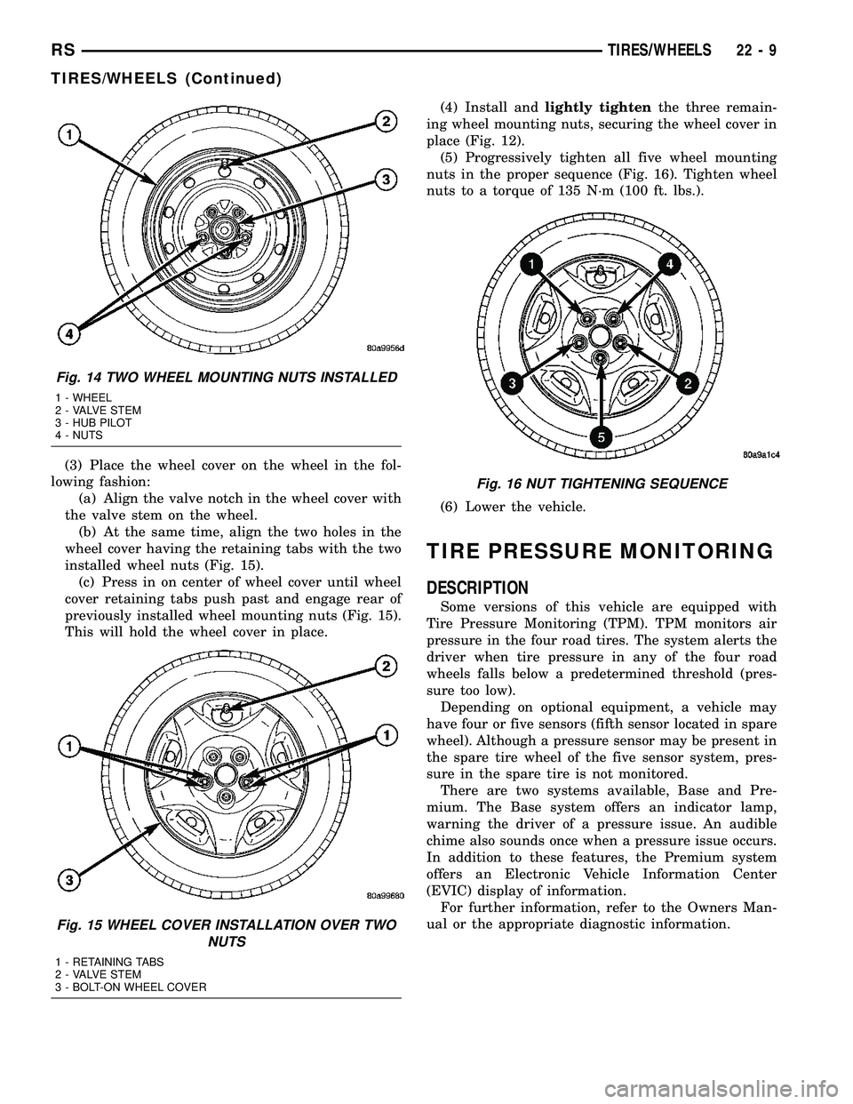
the studs as shown (Fig. 14) to allow proper instal-
lation of the wheel cover.
(2) Using the valve stem as an index placed at the
12 O'clock position, install andlightly tightentwo
wheel mounting nuts on the studs located at the 4
O'clock and 8 O'clock positions as shown (Fig. 14).
Fig. 12 NUTS SECURING WHEEL COVER
1 - VALVE STEM
2 - BOLT-ON WHEEL COVER
3 - NUTS SECURING WHEEL COVER
Fig. 13 Tightening Sequence
22 - 8 TIRES/WHEELSRS
TIRES/WHEELS (Continued)
Page 1766 of 2339

(3) Place the wheel cover on the wheel in the fol-
lowing fashion:
(a) Align the valve notch in the wheel cover with
the valve stem on the wheel.
(b) At the same time, align the two holes in the
wheel cover having the retaining tabs with the two
installed wheel nuts (Fig. 15).
(c) Press in on center of wheel cover until wheel
cover retaining tabs push past and engage rear of
previously installed wheel mounting nuts (Fig. 15).
This will hold the wheel cover in place.(4) Install andlightly tightenthe three remain-
ing wheel mounting nuts, securing the wheel cover in
place (Fig. 12).
(5) Progressively tighten all five wheel mounting
nuts in the proper sequence (Fig. 16). Tighten wheel
nuts to a torque of 135 N´m (100 ft. lbs.).
(6) Lower the vehicle.
TIRE PRESSURE MONITORING
DESCRIPTION
Some versions of this vehicle are equipped with
Tire Pressure Monitoring (TPM). TPM monitors air
pressure in the four road tires. The system alerts the
driver when tire pressure in any of the four road
wheels falls below a predetermined threshold (pres-
sure too low).
Depending on optional equipment, a vehicle may
have four or five sensors (fifth sensor located in spare
wheel). Although a pressure sensor may be present in
the spare tire wheel of the five sensor system, pres-
sure in the spare tire is not monitored.
There are two systems available, Base and Pre-
mium. The Base system offers an indicator lamp,
warning the driver of a pressure issue. An audible
chime also sounds once when a pressure issue occurs.
In addition to these features, the Premium system
offers an Electronic Vehicle Information Center
(EVIC) display of information.
For further information, refer to the Owners Man-
ual or the appropriate diagnostic information.
Fig. 14 TWO WHEEL MOUNTING NUTS INSTALLED
1 - WHEEL
2 - VALVE STEM
3 - HUB PILOT
4 - NUTS
Fig. 15 WHEEL COVER INSTALLATION OVER TWO
NUTS
1 - RETAINING TABS
2 - VALVE STEM
3 - BOLT-ON WHEEL COVER
Fig. 16 NUT TIGHTENING SEQUENCE
RSTIRES/WHEELS22-9
TIRES/WHEELS (Continued)
Page 1776 of 2339

DIAGNOSIS AND TESTING - WHEEL
INSPECTION
Inspect wheels for:
²Excessive runout
²Dents, cracks or irregular bends
²Damaged wheel stud (lug) holes
²Air Leaks
NOTE: Do not attempt to repair a wheel by hammer-
ing, heating or welding.
If a wheel is damaged, an original equipment
replacement wheel should be used. When obtaining
replacement wheels, they must be equivalent in load
carrying capacity. The diameter, width, offset, pilot
hole and bolt circle of the wheel should be the same
as the original wheel.
WARNING: FAILURE TO USE EQUIVALENT
REPLACEMENT WHEELS MAY ADVERSELY
AFFECT THE SAFETY AND HANDLING OF THE
VEHICLE.
WARNING: REPLACEMENT WITH USED WHEELS IS
NOT RECOMMENDED. THE SERVICE HISTORY OF
THE WHEEL MAY HAVE INCLUDED SEVERE TREAT-
MENT OR VERY HIGH MILEAGE. THE RIM COULD
FAIL WITHOUT WARNING.
CLEANING
WHEEL AND WHEEL TRIM CARE
All wheels and wheel trim, especially aluminum
and chrome plated, should be cleaned regularly using
mild soap and water to maintain their luster and to
prevent corrosion. Wash them with the same soap
solution recommended for the body of the vehicle.
When cleaning extremely dirty wheels, care must
be taken in the selection of tire and wheel cleaning
chemicals and equipment to prevent damage to the
wheels. MopartWheel Treatment or MopartChrome
Cleaner is recommended. Any of the ªDO NOT USEº
items listed below can damage wheels and wheel
trim.DO NOT USE:
²Any abrasive cleaner
²Any abrasive cleaning pad (such as steel wool)
or abrasive brush
²Any cleaner that contains an acid which can
react with and discolor the chrome surface.Many
wheel cleaners contain acids that can harm the
wheel surface.
²Oven cleaner
²A car wash that uses carbide-tipped wheel clean-
ing brushes or acidic solutions.
SPECIFICATIONS
WHEEL
SPECIFICATIONS
DESCRIPTION SPECIFICATION
Wheel Mounting (Lug)
Nut Hex Size19 mm
Wheel Mounting Stud
SizeM12 x 1.5 mm
TORQUE SPECIFICATIONS
DESCRIPTION N´mFt.
Lbs.In.
Lbs.
TPM Sensor Mounting Nut 4 Ð 35
Wheel Mounting (Lug ) Nut 135 100 Ð
WHEEL COVER
DESCRIPTION
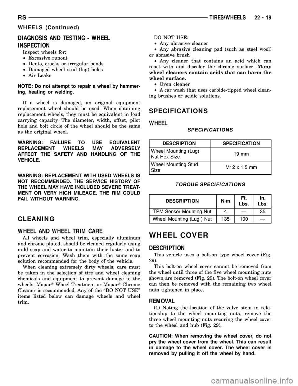
This vehicle uses a bolt-on type wheel cover (Fig.
29).
This bolt-on wheel cover cannot be removed from
the wheel until three of the five wheel mounting nuts
shown are removed (Fig. 29). The bolt-on wheel cover
can then be removed with the remaining two wheel
nuts tightened in place.
REMOVAL
(1) Noting the location of the valve stem in rela-
tionship to the wheel mounting nuts, remove the
three wheel mounting nuts securing the wheel cover
to the wheel and hub (Fig. 29).
CAUTION: When removing the wheel cover, do not
pry the wheel cover from the wheel. This can result
in damage to the wheel cover. The wheel cover is
removed by pulling it off the wheel by hand.
RSTIRES/WHEELS22-19
WHEELS (Continued)
Page 1777 of 2339

(2) Grasp the wheel cover at the edges in line with
the remaining installed wheel nuts and pull straight
outward from the wheel. This will pop the wheel
cover retaining tabs over the two remaining wheel
nuts, removing the wheel cover from the wheel.
INSTALLATION
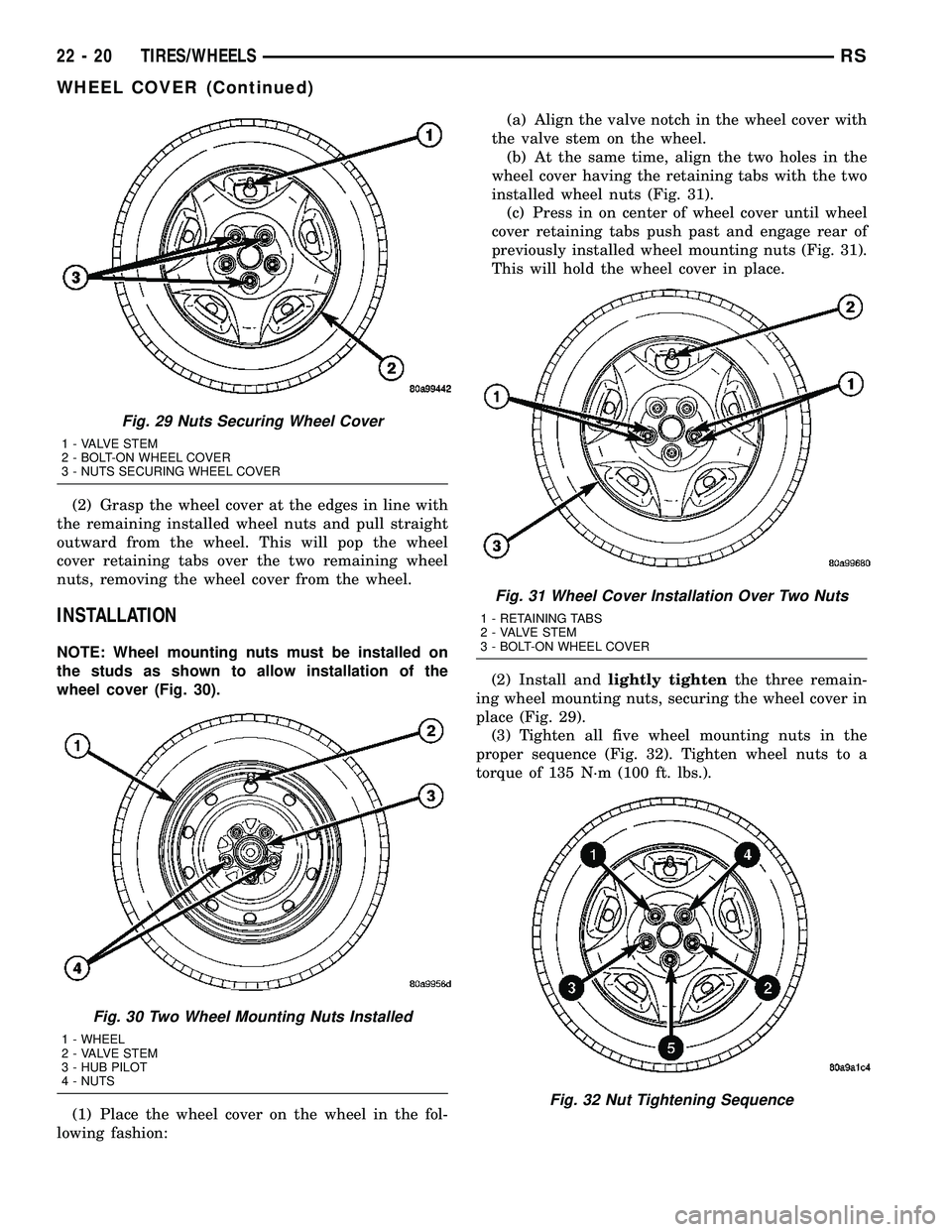
NOTE: Wheel mounting nuts must be installed on
the studs as shown to allow installation of the
wheel cover (Fig. 30).
(1) Place the wheel cover on the wheel in the fol-
lowing fashion:(a) Align the valve notch in the wheel cover with
the valve stem on the wheel.
(b) At the same time, align the two holes in the
wheel cover having the retaining tabs with the two
installed wheel nuts (Fig. 31).
(c) Press in on center of wheel cover until wheel
cover retaining tabs push past and engage rear of
previously installed wheel mounting nuts (Fig. 31).
This will hold the wheel cover in place.
(2) Install andlightly tightenthe three remain-
ing wheel mounting nuts, securing the wheel cover in
place (Fig. 29).
(3) Tighten all five wheel mounting nuts in the
proper sequence (Fig. 32). Tighten wheel nuts to a
torque of 135 N´m (100 ft. lbs.).
Fig. 29 Nuts Securing Wheel Cover
1 - VALVE STEM
2 - BOLT-ON WHEEL COVER
3 - NUTS SECURING WHEEL COVER
Fig. 30 Two Wheel Mounting Nuts Installed
1 - WHEEL
2 - VALVE STEM
3 - HUB PILOT
4 - NUTS
Fig. 31 Wheel Cover Installation Over Two Nuts
1 - RETAINING TABS
2 - VALVE STEM
3 - BOLT-ON WHEEL COVER
Fig. 32 Nut Tightening Sequence
22 - 20 TIRES/WHEELSRS
WHEEL COVER (Continued)
Page 1778 of 2339

WHEEL MOUNTING STUDS -
FRONT
REMOVAL
NOTE: Before proceeding, (Refer to 5 - BRAKES -
WARNING)(Refer to 5 - BRAKES - CAUTION).
CAUTION: Wheel mounting studs MUST NOT be
hammered out of hub flange of hub and bearing
assembly. If a stud is removed by hammering it out,
damage to hub and bearing assembly will occur
leading to premature bearing failure.
(1) Raise vehicle. (Refer to LUBRICATION &
MAINTENANCE/HOISTING - STANDARD PROCE-
DURE)
(2) Remove front wheel and tire assembly. (Refer
to 22 - TIRES/WHEELS - REMOVAL)
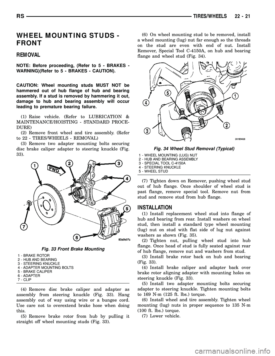
(3) Remove two adapter mounting bolts securing
disc brake caliper adapter to steering knuckle (Fig.
33).
(4) Remove disc brake caliper and adapter as
assembly from steering knuckle (Fig. 33). Hang
assembly out of way using wire or a bungee cord.
Use care not to overextend brake hose when doing
this.
(5) Remove brake rotor from hub by pulling it
straight off wheel mounting studs (Fig. 33).(6) On wheel mounting stud to be removed, install
a wheel mounting (lug) nut far enough so the threads
on the stud are even with end of nut. Install
Remover, Special Tool C-4150A, on hub and bearing
flange and wheel stud (Fig. 34).
(7) Tighten down on Remover, pushing wheel stud
out of hub flange. Once shoulder of wheel stud is
past flange, remove special tool. Remove nut from
stud and remove stud from hub flange.
INSTALLATION
(1) Install replacement wheel stud into flange of
hub and bearing from rear. Install washers on wheel
stud, then install a standard type wheel mounting
(lug) nut on stud with flat side of lug nut against
washers as shown (Fig. 35).
(2) Tighten nut, pulling wheel stud into hub
flange. Once head of stud is fully seated against rear
of hub flange, remove nut and washers from stud.
(3) Install brake rotor back on hub and bearing
(Fig. 33).
(4) Install brake caliper and adapter back over
brake rotor aligning adapter with mounting holes on
steering knuckle (Fig. 33).
(5) Install two adapter mounting bolts securing
adapter to steering knuckle. Tighten mounting bolts
to 169 N´m (125 ft. lbs.) torque.
(6) Install wheel and tire assembly. Tighten wheel
mounting (lug) nuts in proper sequence to 135 N´m
(100 ft. lbs.) torque.
(7) Lower vehicle.
Fig. 33 Front Brake Mounting
1 - BRAKE ROTOR
2 - HUB AND BEARING
3 - STEERING KNUCKLE
4 - ADAPTER MOUNTING BOLTS
5 - BRAKE CALIPER
6 - ADAPTER
7 - CLIP
Fig. 34 Wheel Stud Removal (Typical)
1 - WHEEL MOUNTING (LUG) NUT
2 - HUB AND BEARING ASSEMBLY
3 - SPECIAL TOOL C-4150A
4 - STEERING KNUCKLE
5 - WHEEL STUD
RSTIRES/WHEELS22-21