jump cable CHRYSLER CARAVAN 2005 Service Manual
[x] Cancel search | Manufacturer: CHRYSLER, Model Year: 2005, Model line: CARAVAN, Model: CHRYSLER CARAVAN 2005Pages: 2339, PDF Size: 59.69 MB
Page 38 of 2339
JUMP STARTING
STANDARD PROCEDURE - JUMP STARTING
WARNING: REVIEW ALL SAFETY PRECAUTIONS
AND WARNINGS. (Refer to 8 - ELECTRICAL/BAT-
TERY SYSTEM/BATTERY - STANDARD PROCE-
DURE).
WARNING: DO NOT JUMP START A FROZEN BAT-
TERY, PERSONAL INJURY CAN RESULT.
WARNING: DO NOT JUMP START WHEN MAINTE-
NANCE FREE BATTERY INDICATOR DOT IS BRIGHT
COLOR.
WARNING: DO NOT ALLOW JUMPER CABLE
CLAMPS TO TOUCH EACH OTHER WHEN CON-
NECTED TO A BOOSTER SOURCE.
WARNING: DO NOT USE OPEN FLAME NEAR BAT-
TERYWARNING: REMOVE METALLIC JEWELRY WORN
ON HANDS OR WRISTS TO AVOID INJURY BY
ACCIDENTAL ARCING OF BATTERY CURRENT.
WARNING: WHEN USING A HIGH OUTPUT BOOST-
ING DEVICE, DO NOT ALLOW BATTERY VOLTAGE
TO EXCEED 16 VOLTS.
WARNING: REFER TO INSTRUCTIONS PROVIDED
WITH DEVICE BEING USED.
CAUTION: DO NOT ATTEMPT TO PUSH OR TOW
THE VEHICLE TO START IT. THE VEHICLE CANNOT
BE STARTED THIS WAY. PUSHING WITH ANOTHER
VEHICLE MAY DAMAGE THE TRANSAXLE OR THE
REAR OF THE VEHICLE.
(1) Raise hood on disabled vehicle and visually
inspect engine compartment for:
²Battery cable clamp condition, clean if necessary.
²Frozen battery.
²Clear or bright color test indicator, if equipped.
²Generator drive belt condition and tension.
²Fuel fumes or leakage, correct if necessary.
CAUTION: If the cause of starting problem on dis-
abled vehicle is severe, damage to booster vehicle
charging system can result.
(2) When using another vehicle as a booster
source, park the booster vehicle within cable reach.
Turn off all accessories, set the parking brake, place
the automatic transmission in PARK or the manual
transmission in NEUTRAL and turn the ignition
OFF.
(3) On disabled vehicle, place gear selector in park
or neutral and set park brake. Turn off all accesso-
ries.
(4) Connect jumper cables to booster battery. RED
clamp to positive terminal (+). BLACK clamp to neg-
ative terminal (-). DO NOT allow clamps at opposite
end of cables to touch, electrical arc will result.
Review all warnings in this procedure.
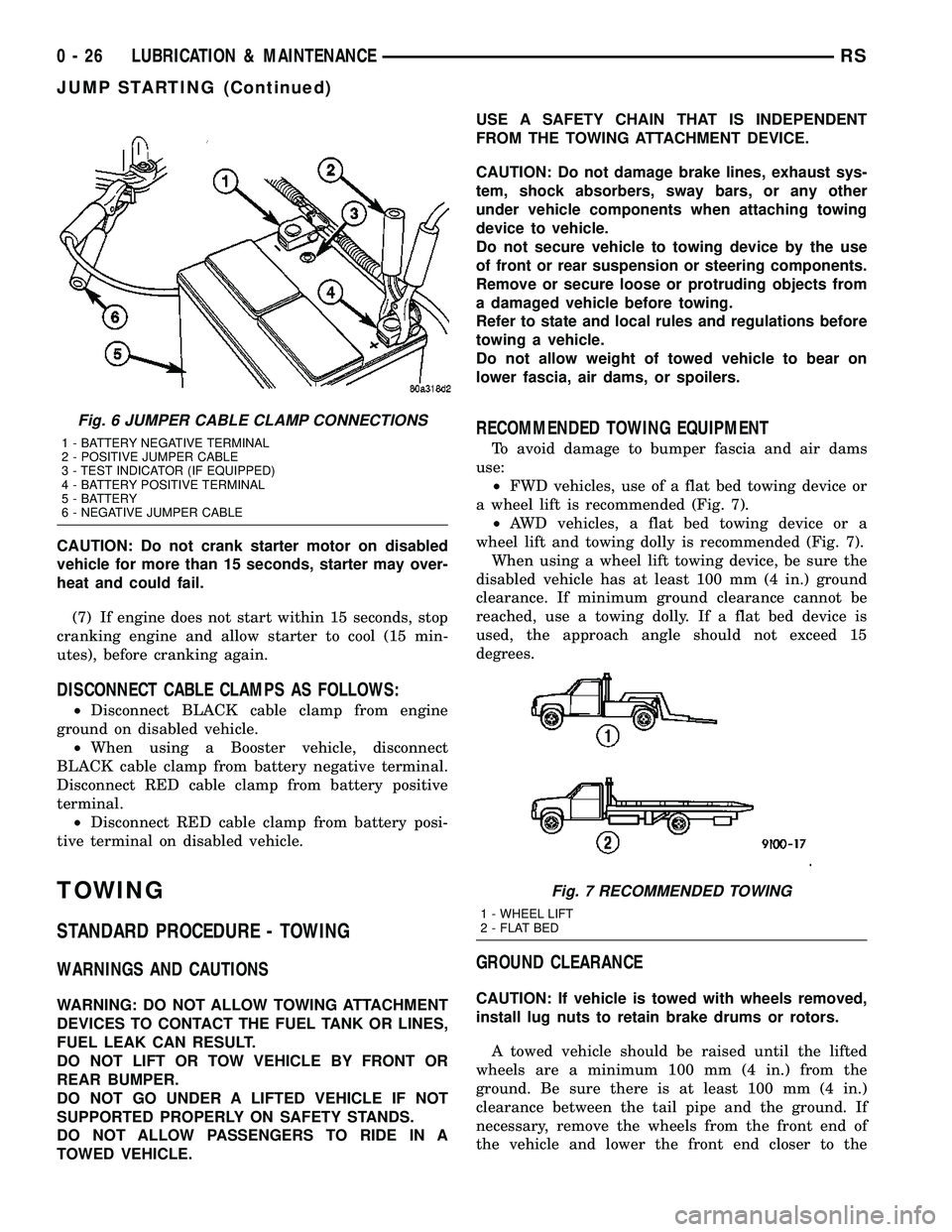
(5) On disabled vehicle, connect RED jumper cable
clamp to positive (+) terminal. Connect BLACK
jumper cable clamp to engine ground as close to the
ground cable attaching point as possible (Fig. 6).
(Refer to 8 - ELECTRICAL/BATTERY SYSTEM/BAT-
TERY - STANDARD PROCEDURE).
(6) Start the engine in the vehicle which has the
booster battery, let the engine idle a few minutes,
then start the engine in the vehicle with the dis-
charged battery.
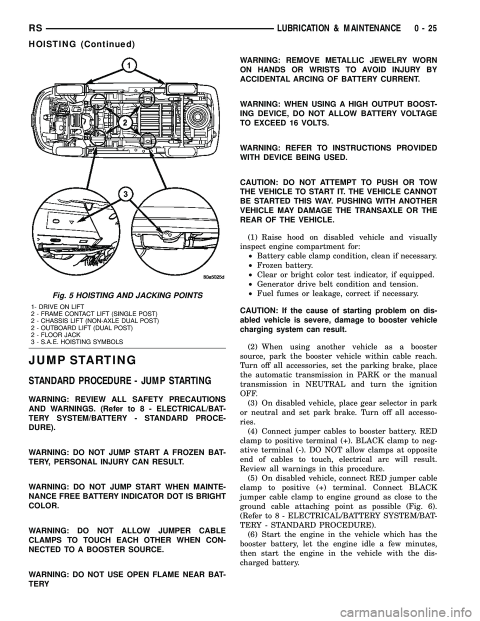
Fig. 5 HOISTING AND JACKING POINTS
1- DRIVE ON LIFT
2 - FRAME CONTACT LIFT (SINGLE POST)
2 - CHASSIS LIFT (NON-AXLE DUAL POST)
2 - OUTBOARD LIFT (DUAL POST)
2 - FLOOR JACK
3 - S.A.E. HOISTING SYMBOLS
RSLUBRICATION & MAINTENANCE0-25
HOISTING (Continued)
Page 39 of 2339
CAUTION: Do not crank starter motor on disabled
vehicle for more than 15 seconds, starter may over-
heat and could fail.
(7) If engine does not start within 15 seconds, stop
cranking engine and allow starter to cool (15 min-
utes), before cranking again.
DISCONNECT CABLE CLAMPS AS FOLLOWS:
²Disconnect BLACK cable clamp from engine
ground on disabled vehicle.
²When using a Booster vehicle, disconnect
BLACK cable clamp from battery negative terminal.
Disconnect RED cable clamp from battery positive
terminal.
²Disconnect RED cable clamp from battery posi-
tive terminal on disabled vehicle.
TOWING
STANDARD PROCEDURE - TOWING
WARNINGS AND CAUTIONS
WARNING: DO NOT ALLOW TOWING ATTACHMENT
DEVICES TO CONTACT THE FUEL TANK OR LINES,
FUEL LEAK CAN RESULT.
DO NOT LIFT OR TOW VEHICLE BY FRONT OR
REAR BUMPER.
DO NOT GO UNDER A LIFTED VEHICLE IF NOT
SUPPORTED PROPERLY ON SAFETY STANDS.
DO NOT ALLOW PASSENGERS TO RIDE IN A
TOWED VEHICLE.USE A SAFETY CHAIN THAT IS INDEPENDENT
FROM THE TOWING ATTACHMENT DEVICE.
CAUTION: Do not damage brake lines, exhaust sys-
tem, shock absorbers, sway bars, or any other
under vehicle components when attaching towing
device to vehicle.
Do not secure vehicle to towing device by the use
of front or rear suspension or steering components.
Remove or secure loose or protruding objects from
a damaged vehicle before towing.
Refer to state and local rules and regulations before
towing a vehicle.
Do not allow weight of towed vehicle to bear on
lower fascia, air dams, or spoilers.
RECOMMENDED TOWING EQUIPMENT
To avoid damage to bumper fascia and air dams
use:
²FWD vehicles, use of a flat bed towing device or
a wheel lift is recommended (Fig. 7).
²AWD vehicles, a flat bed towing device or a
wheel lift and towing dolly is recommended (Fig. 7).
When using a wheel lift towing device, be sure the
disabled vehicle has at least 100 mm (4 in.) ground
clearance. If minimum ground clearance cannot be
reached, use a towing dolly. If a flat bed device is
used, the approach angle should not exceed 15
degrees.
GROUND CLEARANCE
CAUTION: If vehicle is towed with wheels removed,
install lug nuts to retain brake drums or rotors.
A towed vehicle should be raised until the lifted
wheels are a minimum 100 mm (4 in.) from the
ground. Be sure there is at least 100 mm (4 in.)
clearance between the tail pipe and the ground. If
necessary, remove the wheels from the front end of
the vehicle and lower the front end closer to the
Fig. 6 JUMPER CABLE CLAMP CONNECTIONS
1 - BATTERY NEGATIVE TERMINAL
2 - POSITIVE JUMPER CABLE
3 - TEST INDICATOR (IF EQUIPPED)
4 - BATTERY POSITIVE TERMINAL
5 - BATTERY
6 - NEGATIVE JUMPER CABLE
Fig. 7 RECOMMENDED TOWING
1 - WHEEL LIFT
2 - FLAT BED
0 - 26 LUBRICATION & MAINTENANCERS
JUMP STARTING (Continued)
Page 320 of 2339
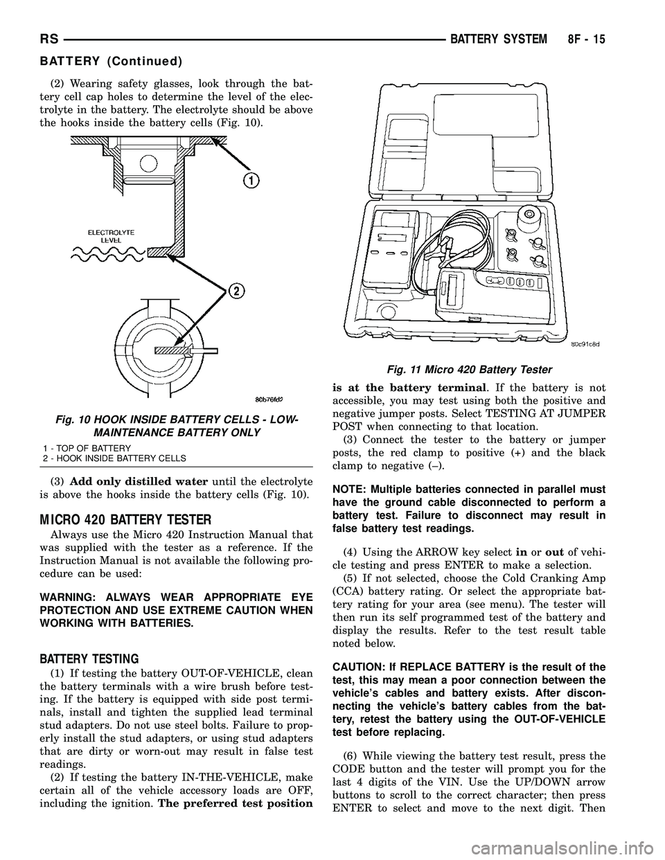
(2) Wearing safety glasses, look through the bat-
tery cell cap holes to determine the level of the elec-
trolyte in the battery. The electrolyte should be above
the hooks inside the battery cells (Fig. 10).
(3)Add only distilled wateruntil the electrolyte
is above the hooks inside the battery cells (Fig. 10).
MICRO 420 BATTERY TESTER
Always use the Micro 420 Instruction Manual that
was supplied with the tester as a reference. If the
Instruction Manual is not available the following pro-
cedure can be used:
WARNING: ALWAYS WEAR APPROPRIATE EYE
PROTECTION AND USE EXTREME CAUTION WHEN
WORKING WITH BATTERIES.
BATTERY TESTING
(1) If testing the battery OUT-OF-VEHICLE, clean
the battery terminals with a wire brush before test-
ing. If the battery is equipped with side post termi-
nals, install and tighten the supplied lead terminal
stud adapters. Do not use steel bolts. Failure to prop-
erly install the stud adapters, or using stud adapters
that are dirty or worn-out may result in false test
readings.
(2) If testing the battery IN-THE-VEHICLE, make
certain all of the vehicle accessory loads are OFF,
including the ignition.The preferred test positionis at the battery terminal. If the battery is not
accessible, you may test using both the positive and
negative jumper posts. Select TESTING AT JUMPER
POST when connecting to that location.
(3) Connect the tester to the battery or jumper
posts, the red clamp to positive (+) and the black
clamp to negative (±).
NOTE: Multiple batteries connected in parallel must
have the ground cable disconnected to perform a
battery test. Failure to disconnect may result in
false battery test readings.
(4) Using the ARROW key selectinoroutof vehi-
cle testing and press ENTER to make a selection.
(5) If not selected, choose the Cold Cranking Amp
(CCA) battery rating. Or select the appropriate bat-
tery rating for your area (see menu). The tester will
then run its self programmed test of the battery and
display the results. Refer to the test result table
noted below.
CAUTION: If REPLACE BATTERY is the result of the
test, this may mean a poor connection between the
vehicle's cables and battery exists. After discon-
necting the vehicle's battery cables from the bat-
tery, retest the battery using the OUT-OF-VEHICLE
test before replacing.
(6) While viewing the battery test result, press the
CODE button and the tester will prompt you for the
last 4 digits of the VIN. Use the UP/DOWN arrow
buttons to scroll to the correct character; then press
ENTER to select and move to the next digit. Then
Fig. 10 HOOK INSIDE BATTERY CELLS - LOW-
MAINTENANCE BATTERY ONLY
1 - TOP OF BATTERY
2 - HOOK INSIDE BATTERY CELLS
Fig. 11 Micro 420 Battery Tester
RSBATTERY SYSTEM8F-15
BATTERY (Continued)
Page 363 of 2339
- DIAGNOSIS AND TESTING). If battery connec-
tions and battery charge is OK proceed to Step 2.
(2) Using a voltmeter, test for battery voltage at
both sides of horn fuse 7. If voltage is OK, on both
sides of fuse, proceed to Fuse OK. If voltage is OK,
on one side of fuse, the fuse is blown, proceed to Step
3.
(3) Using a suitable ammeter in place of the fuse,
test amperage draw of the horn circuit. If amperage
draw is greater than 20 amps without the horn
switch depressed, a grounded circuit exists between
the fuse and the horn relay. Proceed to Step 4. If
amperage draw is greater than 20 amps with the
horn switch depressed, a grounded circuit exists
between the horn relay and the horn. Proceed to step
Step 5.
(4) Remove the horn relay from the IPM. If the
amperage draw drops to 0 amps, the horn switch or
circuit is shorted. If the amperage draw does not
drop to 0 amps, repair short at the IPM.
(5) Disengage a wire connector from one of the
horns. If amperage drops and the connected horn
sounds, replace the faulty horn. If amperage does not
drop with both horns disconnected and the horn
switch depressed, proceed to Step 6.
(6) Using a continuity tester, with the horns dis-
connected test continuity of the X2 cavity of the horn
relay to ground. If continuity is detected, the circuit
is grounded between the Junction Block and the
horns. Locate and repair pinched harness.
FUSE OK
(1) Remove the horn relay from the intelligent
power module.
(2) Using a continuity tester, Depress horn switch
and test continuity from the X3 cavity of the horn
relay to ground.
(a) If continuity is detected, proceed to Step 3.
(b) If NO continuity, proceed to Step 4.
(3) Using a suitable jumper wire, jump across the
fuse F62 cavity and the X2 cavity of the horn relay in
the Junction Block.
(a) If the horn sounds, replace the horn relay.
(b) If the horn does not sound, proceed to Step 4.
(4) Remove airbag trim cover from steering wheel.
Refer to ELECTRICAL, RESTRAINTS.
(5) Test continuity across horn switch connectors
with horn switch depressed.
(a) If continuity is detected, repair open circuit
between the relay and the horn switch.
(b) If NO continuity, replace airbag trim cover.
(6) Install horn relay into intelligent power mod-
ule.
(7) Disengage wire connectors from horns.(8) Using a voltmeter, with the horn switch
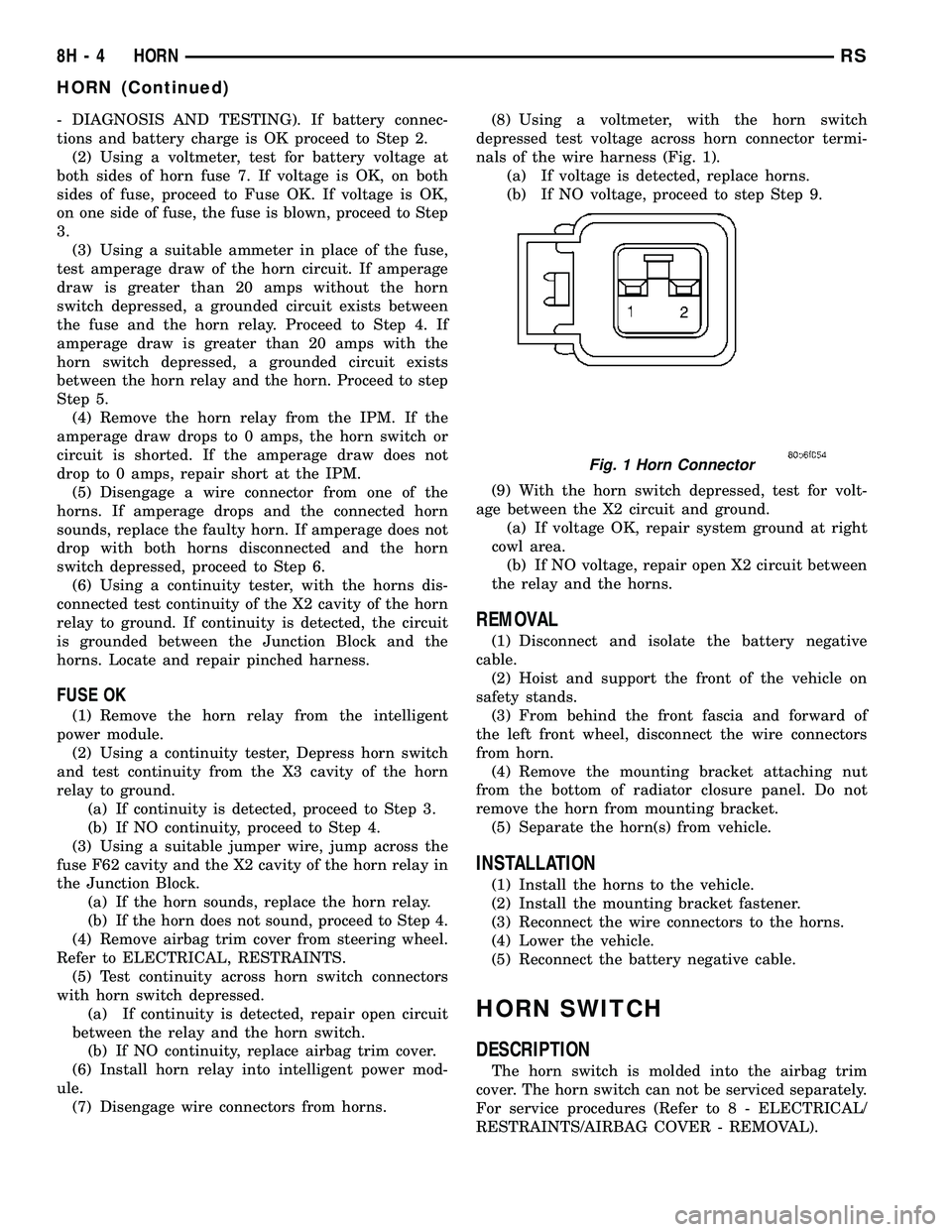
depressed test voltage across horn connector termi-
nals of the wire harness (Fig. 1).
(a) If voltage is detected, replace horns.
(b) If NO voltage, proceed to step Step 9.
(9) With the horn switch depressed, test for volt-
age between the X2 circuit and ground.
(a) If voltage OK, repair system ground at right
cowl area.
(b) If NO voltage, repair open X2 circuit between
the relay and the horns.
REMOVAL
(1) Disconnect and isolate the battery negative
cable.
(2) Hoist and support the front of the vehicle on
safety stands.
(3) From behind the front fascia and forward of
the left front wheel, disconnect the wire connectors
from horn.
(4) Remove the mounting bracket attaching nut
from the bottom of radiator closure panel. Do not
remove the horn from mounting bracket.
(5) Separate the horn(s) from vehicle.
INSTALLATION
(1) Install the horns to the vehicle.
(2) Install the mounting bracket fastener.
(3) Reconnect the wire connectors to the horns.
(4) Lower the vehicle.
(5) Reconnect the battery negative cable.
HORN SWITCH
DESCRIPTION
The horn switch is molded into the airbag trim
cover. The horn switch can not be serviced separately.
For service procedures (Refer to 8 - ELECTRICAL/
RESTRAINTS/AIRBAG COVER - REMOVAL).
Fig. 1 Horn Connector
8H - 4 HORNRS
HORN (Continued)
Page 422 of 2339
(2) Connect a jumper wire between the two termi-
nals in the body half of the ambient temperature sen-
sor wire harness connector.
(3) Check for continuity between the sensor return
circuit and the ambient temperature sensor signal
circuit cavities of the PCM wire harness connector.
There should be continuity. If OK, go to Step 4. If not
OK, repair the open sensor return circuit or ambient
temperature sensor signal circuit to the ambient tem-
perature sensor as required.
(4) Remove the jumper wire from the body half of
the ambient temperature sensor wire harness con-
nector. Check for continuity between the sensor
return circuit cavity of the PCM wire harness connec-
tor and a good ground. There should be no continuity.
If OK, go to Step 5. If not OK, repair the shorted
sensor return circuit as required.
(5) Check for continuity between the ambient tem-
perature sensor signal circuit cavity of the PCM wire
harness connector and a good ground. There should
be no continuity. If OK, (Refer to 8 - ELECTRICAL/
OVERHEAD CONSOLE - DIAGNOSIS AND TEST-ING) to determine the cause. If not OK, repair the
shorted ambient temperature sensor signal circuit as
required.
REMOVAL
(1) Disconnect and isolate the battery negative
cable.
(2) From behind the front bumper fascia, remove
the screw holding the sensor to the radiator closure
panel.
(3) Disconnect the sensor electrical connector.
(4) Remove the sensor from vehicle.
INSTALLATION
(1) Position the sensor in the vehicle and connect
the sensor electrical connector.
(2) From behind the front bumper fascia, install
the sensor mounting screw.
(3) Connect the battery negative cable.
RSOVERHEAD CONSOLE8M-13
AMBIENT TEMP SENSOR (Continued)
Page 485 of 2339
(3) Switch ignition ON position.
(4) Connect the clip end of a 12 volt test light to
Pin 13 in door harness connector at the window
switch. Touch the test light probe to Pin 9 and then
to Pin 11.
²If the test light illuminates, the wiring circuit
between the battery and switch is OK.
²If the lamp does not illuminate, first check the
25 amp circuit breaker attached to the electrical dis-
tribution wiring bracket. If the circuit breaker is OK,
then check the 40 amp fuse (#28) in the Integrated
Power Module (IPM). If both components are OK,
then check for a broken wire.
VENT WINDOW MOTOR
DIAGNOSIS AND TESTING
VENT WINDOW MOTOR
If the power vent window motor is receiving proper
current and ground and does not operate proceed
with motor test. Refer to the appropriate wiring
information.
(1) Remove D-pillar trim panel necessary to gain
access to power vent window motor wire connector,
(Refer to 23 - BODY/INTERIOR/LEFT D-PILLAR
TRIM PANEL - REMOVAL) or (Refer to 23 - BODY/
INTERIOR/RIGHT D-PILLAR TRIM PANEL -
REMOVAL).
(2) Disconnect power vent window motor wire con-
nector from body harness.
(3) Using two jumper wires, connect one to a bat-
tery (+) source and the other to a good ground (-).
(4) Connect the Negative (-) jumper probe to one of
the motor connector terminals.
(5) Momentarily touch the Positive (+) jumper
probe to the other motor connector terminal.
When positive probe is connected the motor should
rotate in one direction to either move window open or
closed. If window is all the way open or closed the
motor will grunt and the crank system will flex when
actuated in that one direction.
Reverse jumper probes at the motor connector ter-
minals and window should now move in opposite
direction. If window does not move or grunt, replace
the motor.
If window moved completely open or closed, reverse
the jumper probes and cycle window to the opposite
position to verify full operation.
If motor grunts and does not move, verify that
crank system is not binding.
REMOVAL
(1) Disconnect and isolate the battery negative
cable.(2) Remove D-pillar trim panel. (Refer to 23 -
BODY/INTERIOR/LEFT D-PILLAR TRIM PANEL -
REMOVAL) or (Refer to 23 - BODY/INTERIOR/
RIGHT D-PILLAR TRIM PANEL - REMOVAL).
(3) Disconnect wire connector from power vent
motor.
(4) Using a flat bladed tool, carefully lift the circu-
lar actuator link tab. Remove link from window ball
socket.
(5) Remove bolts holding power vent motor to
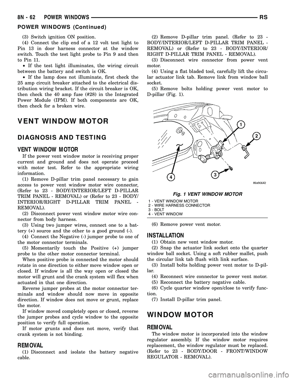
D-pillar (Fig. 1).
(6) Remove power vent motor.
INSTALLATION
(1) Obtain new vent window motor.
(2) Snap the actuator link socket onto the quarter
window ball socket. Using a soft rubber mallet, push
the circular link tab flush with link surface.
(3) Install bolts holding power vent motor to D-pil-
lar.
(4) Reconnect wire connector to power vent motor.
(5) Reconnect the battery negative cable.
(6) Cycle quarter window open/close to verify func-
tion.
(7) Install D-pillar trim panel.
WINDOW MOTOR
REMOVAL
The window motor is incorporated into the window
regulator assembly. If the window motor requires
replacement, the window regulator must be replaced.
(Refer to 23 - BODY/DOOR - FRONT/WINDOW
REGULATOR - REMOVAL).
Fig. 1 VENT WINDOW MOTOR
1 - VENT WINDOW MOTOR
2 - WIRE HARNESS CONNECTOR
3 - BOLT
4 - VENT WINDOW
8N - 62 POWER WINDOWSRS
POWER WINDOWS (Continued)
Page 556 of 2339
OPERATION
When rear wiper operation is required, the BCM
will provide ignition ON voltage to the rear wiper
motor. When the wiper switch is turned OFF, the
BCM provides circuit ground to operate the motor
until the wipe cycle is complete and the wiper arm
returns to the base of the rear window.
The rear wiper/washer switch only offers an inter-
mittent rear wiper mode. The wiper motor will cycle
every 7 seconds. The intermittent delay time is also
adjusted based upon vehicle speed. With the vehicle
traveling greater than 50 mph, the cycle changes to
every 5 seconds.
When rear washer is requested by depressing and
holding down the switch, the BCM then provides a
ground for the rear washer motor. Until the switch is
released, the motor will be in a continuous wipe
mode, then return to an intermittent wipe mode.
WASHER FLUID LEVEL
SWITCH
REMOVAL
(1) Disconnect and isolate the battery negative
cable.
(2) Hoist and support vehicle on hoist or jack
stands.
(3) If necessary, remove the right front wheel and
tire assembly (Refer to 22 - TIRES/WHEELS -
REMOVAL).
(4) Disconnect the right front wheelhouse splash
shield and move aside (Refer to 23 - BODY/EXTERI-
OR/WHEELHOUSE SPLASH SHIELD - REMOVAL).
(5) Drain washer fluid from the reservoir and into
a suitable clean container. This can be done by dis-connecting the windshield washer hose from the
front (outboard) washer pump port allowing the
washer fluid to drain into a container through a tem-
porary jumper hose connected to the front washer
pump.
(6) Disconnect the electrical body harness connec-
tor to the the fluid level sensor. Slide the red lock on
the connector to the release position, then, depress
the black tab and pull the connector off the sensor.
(7) Remove the sensor from reservoir by using a
side foot to gently pry the sensor from the body of
the reservoir. Do not damage the reservoir/sensor
sealing surface or puncture reservoir during removal.
CAUTION: To avoid damage to the sensor, assure
the reservoir is in an upright position before remov-
ing the sensor from the reservoir. Do not rotate the
sensor during removal.
INSTALLATION
(1) Use a new grommet when installing a new sen-
sor assembly.
(2) Assure that the flat of the sensor is aligned
under the ridge of the reservoir and that the sensor
connector is facing down in the fully seated position.
This will allow for proper operation of the sensor
float switch.
(3) Connect the electrical body harness connectors
to the fluid level sensor. Slide the red lock on the
connector to the closed or locked position.
(4) Assure that washer hose is properly routed to
prevent pinching and possible inoperative washers.
(5) Connect the left right front wheelhouse splash
shield and move aside (Refer to 23 - BODY/EXTERI-
OR/WHEELHOUSE SPLASH SHIELD - INSTALLA-
TION).
(6) Install the right front wheel and tire assembly
(Refer to 22 - TIRES/WHEELS - INSTALLATION).
(7) lower vehicle from hoist or jack stands.
(8) Connect the battery negative cable.
(9) Verify system operation.
WASHER HOSES
REMOVAL
(1) Remove washer reservoir from vehicle (Refer to
8 - ELECTRICAL/WIPERS/WASHERS/WASHER
RESERVOIR - REMOVAL).
(2) Disconnect washer hose front the reservoir cav-
ity.
(3) Disconnect the washer hose from the reservoir
pump.
(4) Remove parts as necessary to replace washer
hose (engine compartment, interior components, etc.).
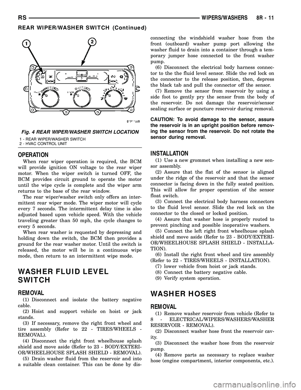
Fig. 4 REAR WIPER/WASHER SWITCH LOCATION
1 - REAR WIPER/WASHER SWITCH
2 - HVAC CONTROL UNIT
RSWIPERS/WASHERS8R-11
REAR WIPER/WASHER SWITCH (Continued)
Page 557 of 2339
INSTALLATION
(1) Install parts as necessary to after replacing
washer hose (engine compartment, interior compo-
nents, etc.).
(2) Connect the washer hose to the reservoir
pump.
(3) Connect washer hose to the reservoir cavity.
(4) Install the washer reservoir into vehicle (Refer
to 8 - ELECTRICAL/WIPERS/WASHERS/WASHER
RESERVOIR - INSTALLATION).
WASHER PUMP MOTOR
REMOVAL
(1) Disconnect and isolate the battery negative
cable.
(2) Hoist and support vehicle on hoist or jack
stands.
(3) If necessary, remove the right front wheel and
tire assembly (Refer to 22 - TIRES/WHEELS -
REMOVAL).
(4) Disconnect the right front wheelhouse splash
shield and move aside (Refer to 23 - BODY/EXTERI-
OR/WHEELHOUSE SPLASH SHIELD - REMOVAL).
(5) Drain washer fluid from the reservoir and into
a suitable clean container. This can be done by dis-
connecting the windshield washer hose from the
front (outboard) washer pump port and allowing the
washer fluid to drain into a container through a tem-
porary jumper hose connected to the front washer
pump port.
(6) Disconnect the electrical body harness connec-
tors to the washer pump motor. Slide the red lock on
the connector to the release position, then, depress
the black tab and pull the connector off the pump.
(7) Remove pump from reservoir by pulling pump
upper retention tab away from reservoir cavity and
then lifting pump up from mounting grommet. Do
not damage reservoir/pump sealing surface or punc-
ture reservoir during removal.
(8) Remove pump grommet and discard.
INSTALLATION
(1) Use new grommet when installing a new pump
assembly.
(2) Assure pump upper retention tab is pressed
into reservoir slot and that pump is rotated flat
against the reservoir and that pump connector is fac-
ing up in the fully seated position. Assure the pump
is aligned to and fully seated in the reservoir cavity.
(3) Connect the electrical body harness connectors
to the washer pump motor. Slide the red lock on the
connector to the closed or locked position.
(4) Assure that washer hose is properly routed to
prevent pinching and possible inoperative washers.(5) Connect the left right front wheelhouse splash
shield and move aside (Refer to 23 - BODY/EXTERI-
OR/WHEELHOUSE SPLASH SHIELD - INSTALLA-
TION).
(6) Install the right front wheel and tire assembly
(Refer to 22 - TIRES/WHEELS - INSTALLATION).
(7) lower vehicle from hoist or jack stands.
(8) Connect the battery negative cable.
(9) Verify system operation.
WASHER RESERVOIR
REMOVAL
(1) Disconnect and isolate the battery negative
cable.
(2) Remove the engine fresh air housing inside the
engine compartment (Refer to 9 - ENGINE/AIR
INTAKE SYSTEM/AIR CLEANER HOUSING -
REMOVAL).
(3) Disconnect the washer hose at the in-line con-
nector forward of the cowl grille so that the in-line
connector remains with the washer hose from the
fresh air plenum.
(4) Disconnect the washer hose from the hose clip
located on the front fender side shield.
(5) Remove the filler tube screw.
(6) Hoist and support vehicle on hoist or jack
stands.
(7) Remove the right front wheel and tire assembly
(Refer to 22 - TIRES/WHEELS - REMOVAL).
(8) Disconnect the left right front wheelhouse
splash shield and move aside (Refer to 23 - BODY/
EXTERIOR/WHEELHOUSE SPLASH SHIELD -
REMOVAL).
(9) Drain washer fluid from the reservoir and into
a suitable clean container. This can be done by dis-
connecting the windshield washer hose from the
front (outboard) washer pump port allowing the
washer fluid to drain into a container through a tem-
porary jumper hose connected to the washer pump
port.
(10) Disconnect the electrical body harness connec-
tors to the washer pump motor and the fluid level
sensor. Slide the red lock on the connector to the
release position, then, depress the black tab and pull
the connector off the pump or sensor.
(11) Remove the two reservoir mounting screws.
(12) Disconnect the reservoir from the body mount
by raising the reservoir upward slightly and then
down so that the reservoir filler neck and front
washer hose pull through the opening in the front
fender side shield.
8R - 12 WIPERS/WASHERSRS
WASHER HOSES (Continued)
Page 1374 of 2339
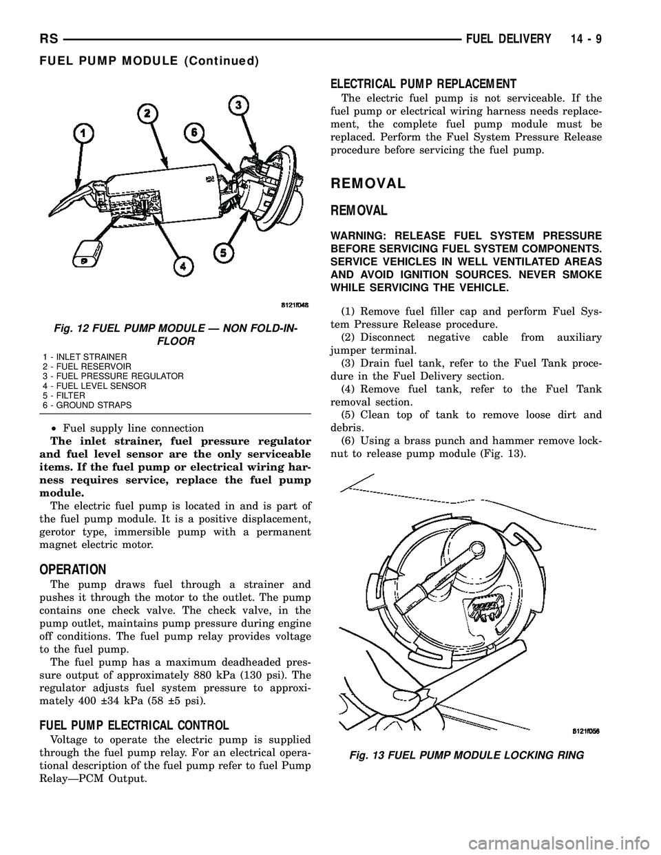
²Fuel supply line connection
The inlet strainer, fuel pressure regulator
and fuel level sensor are the only serviceable
items. If the fuel pump or electrical wiring har-
ness requires service, replace the fuel pump
module.
The electric fuel pump is located in and is part of
the fuel pump module. It is a positive displacement,
gerotor type, immersible pump with a permanent
magnet electric motor.
OPERATION
The pump draws fuel through a strainer and
pushes it through the motor to the outlet. The pump
contains one check valve. The check valve, in the
pump outlet, maintains pump pressure during engine
off conditions. The fuel pump relay provides voltage
to the fuel pump.
The fuel pump has a maximum deadheaded pres-
sure output of approximately 880 kPa (130 psi). The
regulator adjusts fuel system pressure to approxi-
mately 400 34 kPa (58 5 psi).
FUEL PUMP ELECTRICAL CONTROL
Voltage to operate the electric pump is supplied
through the fuel pump relay. For an electrical opera-
tional description of the fuel pump refer to fuel Pump
RelayÐPCM Output.
ELECTRICAL PUMP REPLACEMENT
The electric fuel pump is not serviceable. If the
fuel pump or electrical wiring harness needs replace-
ment, the complete fuel pump module must be
replaced. Perform the Fuel System Pressure Release
procedure before servicing the fuel pump.
REMOVAL
REMOVAL
WARNING: RELEASE FUEL SYSTEM PRESSURE
BEFORE SERVICING FUEL SYSTEM COMPONENTS.
SERVICE VEHICLES IN WELL VENTILATED AREAS
AND AVOID IGNITION SOURCES. NEVER SMOKE
WHILE SERVICING THE VEHICLE.
(1) Remove fuel filler cap and perform Fuel Sys-
tem Pressure Release procedure.
(2) Disconnect negative cable from auxiliary
jumper terminal.
(3) Drain fuel tank, refer to the Fuel Tank proce-
dure in the Fuel Delivery section.
(4) Remove fuel tank, refer to the Fuel Tank
removal section.
(5) Clean top of tank to remove loose dirt and
debris.
(6) Using a brass punch and hammer remove lock-
nut to release pump module (Fig. 13).
Fig. 12 FUEL PUMP MODULE Ð NON FOLD-IN-
FLOOR
1 - INLET STRAINER
2 - FUEL RESERVOIR
3 - FUEL PRESSURE REGULATOR
4 - FUEL LEVEL SENSOR
5 - FILTER
6 - GROUND STRAPS
Fig. 13 FUEL PUMP MODULE LOCKING RING
RSFUEL DELIVERY14-9
FUEL PUMP MODULE (Continued)
Page 1383 of 2339
QUICK CONNECT FITTING
STANDARD PROCEDURE - QUICK-CONNECT
FITTINGS
REMOVAL
When disconnecting a quick-connect fitting, the
retainer will remain on the fuel tube nipple.
WARNING: RELEASE FUEL SYSTEM PRESSURE
BEFORE DISCONNECTING A QUICK-CONNECT FIT-
TINGS. REFER TO THE FUEL PRESSURE RELEASE
PROCEDURE. THIS MAY RESULT IN PERSONAL
INJURY OR DEATH.
(1) Perform Fuel Pressure Release Procedure.
Refer to the Fuel Pressure Release Procedure in this
section.
(2) Disconnect negative cable from battery or aux-
iliary jumper terminal.
(3) Squeeze retainer tabs together and pull fuel
tube/quick-connect fitting assembly off of fuel tube
nipple. The retainer will remain on fuel tube.
INSTALLATION
CAUTION: Make sure that the o-ring in installed in
fitting. Never install a quick-connect fitting without
the retainer being either on the fuel tube or already
in the quick-connect fitting. In either case, ensure
the retainer locks securely into the quick-connect
fitting by firmly push-pulling-push on fuel tube and
fitting to ensure it is secured.
(1) Using a clean lint free cloth, clean the fuel tube
nipple and retainer.
(2) Prior to connecting the fitting to the fuel tube,
coat the fuel tube nipple with clean engine oil.
(3) Push the quick-connect fitting over the fuel
tube until theretainer seats and a click is heard.
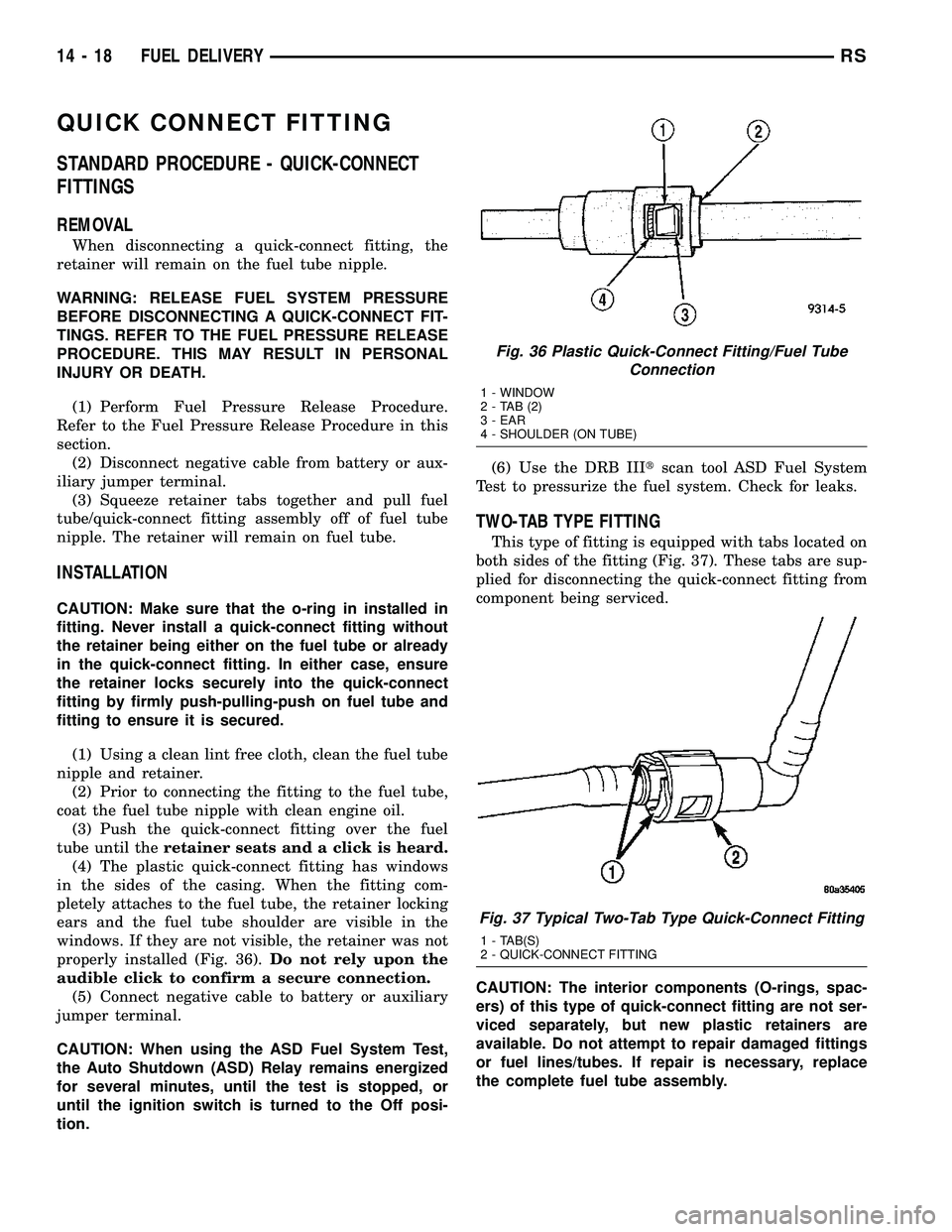
(4) The plastic quick-connect fitting has windows
in the sides of the casing. When the fitting com-
pletely attaches to the fuel tube, the retainer locking
ears and the fuel tube shoulder are visible in the
windows. If they are not visible, the retainer was not
properly installed (Fig. 36).Do not rely upon the
audible click to confirm a secure connection.
(5) Connect negative cable to battery or auxiliary
jumper terminal.
CAUTION: When using the ASD Fuel System Test,
the Auto Shutdown (ASD) Relay remains energized
for several minutes, until the test is stopped, or
until the ignition switch is turned to the Off posi-
tion.(6) Use the DRB IIItscan tool ASD Fuel System
Test to pressurize the fuel system. Check for leaks.
TWO-TAB TYPE FITTING
This type of fitting is equipped with tabs located on
both sides of the fitting (Fig. 37). These tabs are sup-
plied for disconnecting the quick-connect fitting from
component being serviced.
CAUTION: The interior components (O-rings, spac-
ers) of this type of quick-connect fitting are not ser-
viced separately, but new plastic retainers are
available. Do not attempt to repair damaged fittings
or fuel lines/tubes. If repair is necessary, replace
the complete fuel tube assembly.
Fig. 36 Plastic Quick-Connect Fitting/Fuel Tube
Connection
1 - WINDOW
2-TAB(2)
3 - EAR
4 - SHOULDER (ON TUBE)
Fig. 37 Typical Two-Tab Type Quick-Connect Fitting
1 - TAB(S)
2 - QUICK-CONNECT FITTING
14 - 18 FUEL DELIVERYRS