jump cable CHRYSLER CARAVAN 2005 User Guide
[x] Cancel search | Manufacturer: CHRYSLER, Model Year: 2005, Model line: CARAVAN, Model: CHRYSLER CARAVAN 2005Pages: 2339, PDF Size: 59.69 MB
Page 1384 of 2339
WARNING: THE FUEL SYSTEM IS UNDER A CON-
STANT PRESSURE (EVEN WITH THE ENGINE OFF).
BEFORE SERVICING ANY FUEL SYSTEM HOSES,
FITTINGS OR LINES, THE FUEL SYSTEM PRES-
SURE MUST BE RELEASED. REFER TO THE FUEL
PRESSURE RELEASE PROCEDURE IN THIS
GROUP. THIS MAY RESULT IN PERSONAL INJURY
OR DEATH.
DISCONNECTION/CONNECTION
(1) Perform fuel pressure release procedure. Refer
to Fuel Pressure Release Procedure in this group.
(2) Disconnect negative battery cable from battery
or auxiliary jumper terminal.
(3) Clean fitting of any foreign material before dis-
assembly.
(4) To disconnect quick-connect fitting, squeeze
plastic retainer tabs (Fig. 37) against sides of quick-
connect fitting with your fingers. Tool use is not
required for removal and may damage plastic
retainer. Pull fitting from fuel system component
being serviced. The plastic retainer will remain on
component being serviced after fitting is discon-
nected. The O-rings and spacer will remain in quick-
connect fitting connector body.
(5) Inspect quick-connect fitting body and compo-
nent for damage. Replace as necessary.
CAUTION: When the quick-connect fitting was dis-
connected, the plastic retainer will remain on the
component being serviced. If this retainer must be
removed, very carefully release the retainer from
the component with two small screwdrivers. After
removal, inspect the retainer for cracks or any dam-
age.
(6) Prior to connecting quick-connect fitting to
component being serviced, check condition of fitting
and component. Clean parts with a lint-free cloth.
Lubricate with clean engine oil.
(7) Insert quick-connect fitting to component being
serviced and into plastic retainer. When a connection
is made, a click will be heard.
(8) Verify a locked condition by firmly push-pull-
ing-push on fuel tube and fitting (15-30 lbs.).
(9) Connect negative cable to battery or auxiliary
jumper terminal.
(10) Use the DRB IIItscan tool ASD Fuel System
Test to pressurize the fuel system. Check for leaks.PLASTIC RETAINER RING TYPE FITTING
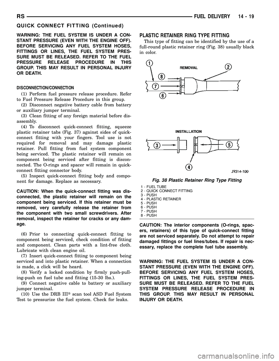
This type of fitting can be identified by the use of a
full-round plastic retainer ring (Fig. 38) usually black
in color.
CAUTION: The interior components (O-rings, spac-
ers, retainers) of this type of quick-connect fitting
are not serviced separately. Do not attempt to repair
damaged fittings or fuel lines/tubes. If repair is nec-
essary, replace the complete fuel tube assembly.
WARNING: THE FUEL SYSTEM IS UNDER A CON-
STANT PRESSURE (EVEN WITH THE ENGINE OFF).
BEFORE SERVICING ANY FUEL SYSTEM HOSES,
FITTINGS OR LINES, THE FUEL SYSTEM PRES-
SURE MUST BE RELEASED. REFER TO THE FUEL
SYSTEM PRESSURE RELEASE PROCEDURE IN
THIS GROUP. THIS MAY RESULT IN PERSONAL
INJURY OR DEATH.
Fig. 38 Plastic Retainer Ring Type Fitting
1 - FUEL TUBE
2 - QUICK CONNECT FITTING
3 - PUSH
4 - PLASTIC RETAINER
5 - PUSH
6 - PUSH
7 - PUSH
8 - PUSH
RSFUEL DELIVERY14-19
QUICK CONNECT FITTING (Continued)
Page 1385 of 2339
DISCONNECTION/CONNECTION
(1) Perform fuel pressure release procedure. Refer
to Fuel Pressure Release Procedure in this section.
(2) Disconnect negative battery cable from battery
or auxiliary jumper terminal.
(3) Clean fitting of any foreign material before dis-
assembly.
(4) To release fuel system component from quick-
connect fitting, firmly push fitting towards compo-
nent being serviced while firmly pushing plastic
retainer ring into fitting (Fig. 38). With plastic ring
depressed, pull fitting from component.The plastic
retainer ring must be pressed squarely into fit-
ting body. If this retainer is cocked during
removal, it may be difficult to disconnect fit-
ting. Use an open-end wrench on shoulder of
plastic retainer ring to aid in disconnection.(5) After disconnection, plastic retainer ring will
remain with quick-connect fitting connector body.
(6) Inspect fitting connector body, plastic retainer
ring and fuel system component for damage. Replace
as necessary.
(7) Prior to connecting quick-connect fitting to
component being serviced, check condition of fitting
and component. Clean parts with a lint-free cloth.
Lubricate with clean engine oil.
(8) Insert quick-connect fitting into component
being serviced until a click is felt.
(9) Verify a locked condition by firmly push-pull-
ing-push on fuel tube and fitting (15-30 lbs.).
(10) Connect negative battery cable to battery or
auxiliary jumper terminal.
(11) Use the DRB IIItscan tool ASD Fuel System
Test to pressurize the fuel system. Check for leaks.
14 - 20 FUEL DELIVERYRS
QUICK CONNECT FITTING (Continued)
Page 2171 of 2339
REMOVAL
WARNING: ON VEHICLES EQUIPPED WITH AIR-
BAGS, DISABLE THE AIRBAG SYSTEM BEFORE
ATTEMPTING ANY STEERING WHEEL, STEERING
COLUMN, OR INSTRUMENT PANEL COMPONENT
DIAGNOSIS OR SERVICE. DISCONNECT AND ISO-
LATE THE BATTERY NEGATIVE (GROUND) CABLE,
THEN WAIT TWO MINUTES FOR THE AIRBAG SYS-
TEM CAPACITOR TO DISCHARGE BEFORE PER-
FORMING FURTHER DIAGNOSIS OR SERVICE. THIS
IS THE ONLY SURE WAY TO DISABLE THE AIRBAG
SYSTEM. FAILURE TO TAKE THE PROPER PRE-
CAUTIONS COULD RESULT IN ACCIDENTAL AIR-
BAG DEPLOYMENT AND POSSIBLE PERSONAL
INJURY.
(1) Disconnect and isolate the battery negative
cable.
(2) Remove the center bezel from the instrument
panel (Refer to 23 - BODY/INSTRUMENT PANEL/
INSTRUMENT PANEL CENTER BEZEL -
REMOVAL).
(3) Place the instrument panel center bezel unit
face down on a suitable work surface. Take the
proper precautions to protect the center bezel from
cosmetic damage.
(4) If the vehicle is equipped with the optional
Automatic Temperature Control (ATC) system, dis-
connect the infrared sensor jumper harness connector
from the receptacle on the back of the A/C-heater
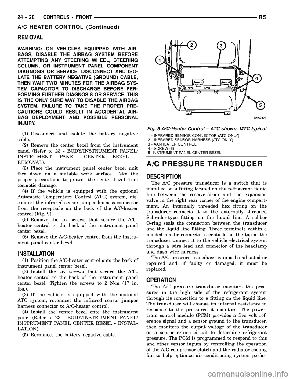
control (Fig. 9).
(5) Remove the six screws that secure the A/C-
heater control to the back of the instrument panel
center bezel.
(6) Remove the A/C-heater control from the instru-
ment panel center bezel.
INSTALLATION
(1) Position the A/C-heater control onto the back of
instrument panel center bezel.
(2) Install the six screws that secure the A/C-
heater control to the back of the instrument panel
center bezel. Tighten the screws to 2 N´m (17 in.
lbs.).
(3) If the vehicle is equipped with the optional
ATC system, reconnect the infrared sensor jumper
harness connector to A/C-heater control.
(4) Install the center bezel onto the instrument
panel (Refer to 23 - BODY/INSTRUMENT PANEL/
INSTRUMENT PANEL CENTER BEZEL - INSTAL-
LATION).
(5) Reconnect the battery negative cable.
A/C PRESSURE TRANSDUCER
DESCRIPTION
The A/C pressure transducer is a switch that is
installed on a fitting located on the refrigerant liquid
line between the receiver/drier and the expansion
valve in the right rear corner of the engine compart-
ment. An internally threaded hex fitting on the
transducer connects it to the externally threaded
Schrader-type fitting on the liquid line. A rubber
O-ring seals the connection between the transducer
and the liquid line fitting. Three terminals within a
molded plastic connector receptacle on the top of the
transducer connect it to the vehicle electrical system
through a wire lead and connector of the headlamp
and dash wire harness.
The A/C pressure transducer cannot be adjusted or
repaired and, if faulty or damaged, it must be
replaced.
OPERATION
The A/C pressure transducer monitors the pres-
sures in the high side of the refrigerant system
through its connection to a fitting on the liquid line.
The transducer will change its internal resistance in
response to the pressures it monitors. The power-
train control module (PCM) provides a five volt ref-
erence signal and a sensor ground to the transducer,
then monitors the output voltage of the transducer
on a sensor return circuit to determine refrigerant
pressure. The PCM is programmed to respond to this
and other sensor inputs by controlling the operation
of the A/C compressor clutch and the radiator cooling
fan to help optimize air conditioning system perfor-
Fig. 9 A/C-Heater Control ± ATC shown, MTC typical
1 - INFRARED SENSOR CONNECTOR (ATC ONLY)
2 - INFRARED SENSOR HARNESS (ATC ONLY)
3 - A/C-HEATER CONTROL
4 - SCREW (6)
5- INSTRUMENT PANEL CENTER BEZEL
24 - 20 CONTROLS - FRONTRS
A/C HEATER CONTROL (Continued)
Page 2179 of 2339

(8) Run the HVAC Cool Down test to verify system
is operating properly (Refer to 24 - HEATING & AIR
CONDITIONING - DIAGNOSIS AND TESTING).
RS MODELS
(1) Install the evaporator temperature sensor into
the top of the HVAC housing.
(2) Connect the wire harness connector to the
evaporator temperature sensor.
(3) Install the instrument panel (Refer to 23 -
BODY/INSTRUMENT PANEL/INSTRUMENT
PANEL ASSEMBLY - INSTALLATION).
(4) Reconnect the negative battery cable.
INFRARED TEMPERATURE
SENSOR
DESCRIPTION
The infrared temperature sensor consists of two
infrared transducers that are concealed behind a
clear lens located near the bottom of the center panel
outlet near the top of the instrument panel center
bezel (Fig. 19). These sensors are used only on mod-
els equipped with the optional automatic tempera-
ture control (ATC) heating-A/C system. A molded
plastic connector receptacle on the bottom of the
panel outlet unit is concealed behind the center
bezel. A short, dedicated jumper wire harness routedbehind the center bezel connects the sensors directly
to the ATC A/C-heater control module near the bot-
tom of the center bezel. The infrared temperature
sensor is integral to the center bezel panel outlet
unit. The infrared sensors cannot be adjusted or
repaired and, if faulty or damaged, the center bezel
must be replaced.
OPERATION
The dual infrared temperature sensors provide
independent measurement inputs to the Automatic
Temperature Control (ATC) heater-A/C control mod-
ule that indicates the surface temperature of the
driver seat and front seat passenger seat occupants.
By using a surface temperature measurement, rather
than an air temperature measurement, the ATC sys-
tem is able to adjust itself to the comfort level as per-
ceived by the occupant. This allows the system to
detect and compensate for other ambient conditions
affecting comfort levels, such as solar heat gain or
evaporative heat loss. The ATC system logic responds
to the infrared sensor inputs by calculating and
adjusting the air flow temperature and air flow rate
needed to properly obtain and maintain the individ-
ually selected comfort level temperatures of both the
driver and passenger seat occupants. The ATC heat-
er-A/C control module continually monitors the infra-
red sensor circuits, and will store a Diagnostic
Trouble Code (DTC) for any problem it detects. This
DTC information can be retrieved and the infrared
temperature sensor diagnosed using a DRBIIItscan
tool. Refer to Body Diagnostic Procedures.
Fig. 18 Evaporator Temperature Sensor - RS Models
1 - EVAPORATOR TEMPERATURE SENSOR
2 - WIRE HARNESS CONNECTOR
3 - HVAC HOUSING
Fig. 19 Infrared Temperature Sensor ± RS shown,
RG typical
1 - INSTRUMENT PANEL CENTER BEZEL
2 - CENTER IP AIR OUTLETS
3 - INFRARED TEMPERATURE SENSOR
24 - 28 CONTROLS - FRONTRS
EVAPORATOR TEMPERATURE SENSOR (Continued)
Page 2195 of 2339
REMOVAL
FRONT CENTER BEZEL OUTLETS
The three outlets located near the top of the
instrument panel center bezel are serviced only as a
set of all three outlets. If the vehicle is equipped with
the optional automatic temperature control (ATC)
system, the center outlet of the three has fixed vanes
and also houses the remote front infrared tempera-
ture sensors.
WARNING: ON VEHICLES EQUIPPED WITH AIR-
BAGS, DISABLE THE AIRBAG SYSTEM BEFORE
ATTEMPTING ANY STEERING WHEEL, STEERING
COLUMN, OR INSTRUMENT PANEL COMPONENT
DIAGNOSIS OR SERVICE. DISCONNECT AND ISO-
LATE THE BATTERY NEGATIVE (GROUND) CABLE,
THEN WAIT TWO MINUTES FOR THE AIRBAG SYS-
TEM CAPACITOR TO DISCHARGE BEFORE PER-
FORMING FURTHER DIAGNOSIS OR SERVICE. THIS
IS THE ONLY SURE WAY TO DISABLE THE AIRBAG
SYSTEM. FAILURE TO TAKE THE PROPER PRE-
CAUTIONS COULD RESULT IN ACCIDENTAL AIR-
BAG DEPLOYMENT AND POSSIBLE PERSONAL
INJURY.
(1) Disconnect and isolate the negative battery
cable.
(2) Remove the center bezel from the instrument
panel (Refer to 23 - BODY/INSTRUMENT PANEL/
INSTRUMENT PANEL CENTER BEZEL -
REMOVAL).
(3) Place the center bezel face down on a suitable
work surface. Be certain to take the proper precau-
tions to protect the face of the center bezel from cos-
metic damage.
(4) If the vehicle is equipped with the optional
ATC system, disconnect the ATC remote infrared
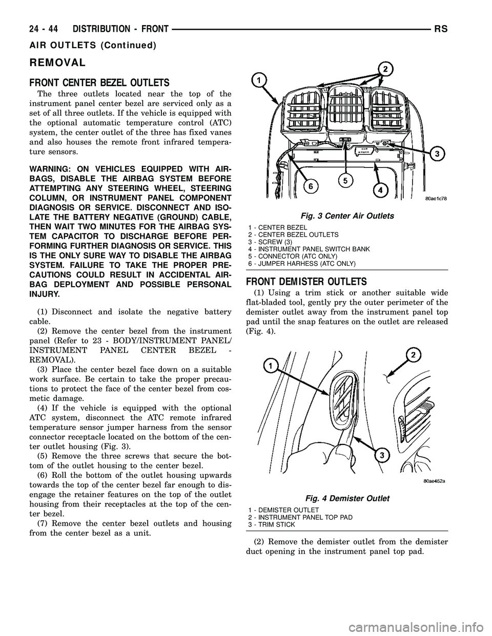
temperature sensor jumper harness from the sensor
connector receptacle located on the bottom of the cen-
ter outlet housing (Fig. 3).
(5) Remove the three screws that secure the bot-
tom of the outlet housing to the center bezel.
(6) Roll the bottom of the outlet housing upwards
towards the top of the center bezel far enough to dis-
engage the retainer features on the top of the outlet
housing from their receptacles at the top of the cen-
ter bezel.
(7) Remove the center bezel outlets and housing
from the center bezel as a unit.
FRONT DEMISTER OUTLETS
(1) Using a trim stick or another suitable wide
flat-bladed tool, gently pry the outer perimeter of the
demister outlet away from the instrument panel top
pad until the snap features on the outlet are released
(Fig. 4).
(2) Remove the demister outlet from the demister
duct opening in the instrument panel top pad.
Fig. 3 Center Air Outlets
1 - CENTER BEZEL
2 - CENTER BEZEL OUTLETS
3 - SCREW (3)
4 - INSTRUMENT PANEL SWITCH BANK
5 - CONNECTOR (ATC ONLY)
6 - JUMPER HARHESS (ATC ONLY)
Fig. 4 Demister Outlet
1 - DEMISTER OUTLET
2 - INSTRUMENT PANEL TOP PAD
3 - TRIM STICK
24 - 44 DISTRIBUTION - FRONTRS
AIR OUTLETS (Continued)
Page 2196 of 2339

INSTRUMENT PANEL OUTLETS
(1) Using a trim stick or another suitable wide
flat-bladed tool, gently pry the outer perimeter of the
instrument panel outlet away from the instrument
panel top pad until the snap features on the outlet
are released (Fig. 5).
(2) Remove the instrument panel outlet from the
panel duct opening in the instrument panel top pad.
INSTALLATION
FRONT CENTER BEZEL OUTLETS
(1) Position the center bezel outlets and housing
onto the center bezel as a unit.
(2) Engage the retainer features on the top of the
outlet housing with their receptacles at the top of the
center bezel, then roll the bottom of the outlet hous-
ing downwards towards the center bezel.
(3) Install the three screws that secure the bottom
of the outlet housing to the center bezel. Tighten the
screws to 2 N´m (17 in. lbs.).
(4) If the vehicle is equipped with the optional
ATC system, reconnect the ATC remote infrared tem-
perature sensor jumper harness to the sensor connec-
tor receptacle located on the bottom of the center
outlet housing.
(5) Reinstall the center bezel onto the instrument
panel (Refer to 23 - BODY/INSTRUMENT PANEL/
INSTRUMENT PANEL CENTER BEZEL - INSTAL-
LATION).
(6) Reconnect the battery negative cable.
FRONT DEMISTER OUTLETS
(1) Position the demister outlet over the demister
duct opening in the instrument panel top pad.(2) Using hand pressure, press the demister outlet
firmly and evenly into the instrument panel top pad
opening until the snap features on the outlet are
fully engaged.
INSTRUMENT PANEL OUTLETS
(1) Position the instrument panel outlet into the
panel duct opening in the instrument panel top pad.
(2) Using hand pressure, press the instrument
panel outlet firmly and evenly into the instrument
panel top pad opening until the snap features on the
outlet are fully engaged.
BLOWER MOTOR
DESCRIPTION
The blower motor is a 12-volt, Direct Current (DC)
motor with a squirrel cage-type blower wheel that is
secured to the blower motor shaft (Fig. 6). The
blower motor and wheel are located near the passen-
ger side end of the HVAC housing in the passenger
compartment below the instrument panel. The
blower motor and blower motor wheel are factory bal-
anced and cannot be adjusted or repaired. If faulty or
damaged, the blower motor and blower wheel must
be replaced as an assembly.
OPERATION
On models equipped with the manual heater-A/C
system, the blower motor will operate whenever the
ignition switch is in the On position and the blower
control switch is in any position except Off. On mod-
els equipped with the Automatic Temperature Con-
trol (ATC) system, the blower motor will operate
Fig. 5 Instrument Panel Outlet - Left Side Shown
1 - INSTRUMENT PANEL TOP PAD
2 - INSTRUMENT PANEL OUTLET
3 - TRIM STICK
Fig. 6 Blower Motor
1 - BLOWER MOTOR
2 - RUBBER GROMMET
3 - BLOWER MOTOR CONNECTOR
4 - MOUNTING TABS
RSDISTRIBUTION - FRONT24-45
AIR OUTLETS (Continued)
Page 2197 of 2339
whenever the ignition switch is in the On position
and the A/C-heater control power is turned on.
The blower motor receives battery current when-
ever the front blower motor relay is energized. The
front blower motor relay output circuit is protected
by a fuse in the Integrated Power Module (IPM)
located in the engine compartment near the battery.
In the manual heater-A/C system, the blower motor
speed is controlled by regulating the path to ground
through the blower control switch and the blower
motor resistor. In the ATC system, the blower motor
speed is controlled by an electronic blower motor
power module, which uses a pulse width modulated
input from the ATC module and feedback from the
blower motor to regulate the blower motor ground
path it provides. The blower motor and wheel are
used to control the velocity of air moving through the
HVAC housing by spinning the blower wheel within
the housing at the selected speed or, in the ATC sys-
tem, at the selected or programmed speed.
DIAGNOSIS AND TESTING
FRONT BLOWER MOTOR
BLOWER MOTOR INOPERATIVE
WARNING: ON VEHICLES EQUIPPED WITH AIR-
BAGS, DISABLE THE AIRBAG SYSTEM BEFORE
ATTEMPTING ANY STEERING WHEEL, STEERING
COLUMN, OR INSTRUMENT PANEL COMPONENT
DIAGNOSIS OR SERVICE. DISCONNECT AND ISO-
LATE THE BATTERY NEGATIVE (GROUND) CABLE,
THEN WAIT TWO MINUTES FOR THE AIRBAG SYS-
TEM CAPACITOR TO DISCHARGE BEFORE PER-
FORMING FURTHER DIAGNOSIS OR SERVICE. THIS
IS THE ONLY SURE WAY TO DISABLE THE AIRBAG
SYSTEM. FAILURE TO TAKE THE PROPER PRE-
CAUTIONS COULD RESULT IN ACCIDENTAL AIR-
BAG DEPLOYMENT AND POSSIBLE PERSONAL
INJURY.
For circuit descriptions and diagrams, refer to the
appropriate wiring information. The wiring informa-
tion includes wiring, diagrams, proper wire and con-
nector repair procedures, further details on wire
harness routing and retention, as well as pin-out and
location views for the various wire harness connec-
tors, splices and grounds.BLOWER MOTOR ELECTRICAL DIAGNOSIS
(1) Check the fuse (Fuse 10 - 40 ampere) in the
Integrated Power Module (IPM). If OK, go to Step 2.
If not OK, repair the shorted circuit or component as
required and replace the faulty fuse.
(2) Turn the ignition switch to the On position. Be
certain that the A/C-heater control power is turned
on. Check for battery voltage at the fuse (Fuse 10 -
40 ampere) in the IPM. If OK, go to Step 3. If not
OK, check the front blower motor relay.
(3) Turn the ignition switch to the Off position.
Disconnect and isolate the battery negative cable.
Disconnect the front HVAC wire harness connector
for the front blower motor resistor block (Manual
Temperature Control) or the front blower motor
power module (Automatic Temperature Control) from
the resistor or module connector receptacle. Recon-
nect the battery negative cable. Turn the ignition
switch to the On position. Be certain that the A/C-
heater control power is turned on. Check for battery
voltage at the fused front blower motor relay output
circuit cavity of the front HVAC wire harness connec-
tor for the front blower motor resistor block (MTC) or
the front blower motor power module (ATC). If OK,
go to Step 4. If not OK, repair the open fused front
blower motor relay output circuit to the IPM as
required.
(4) Turn the ignition switch to the Off position.
Disconnect and isolate the battery negative cable.
Disconnect the front blower motor pigtail wire con-
nector from the connector receptacle of the front
blower motor resistor block (MTC) or the front
blower motor power module (ATC). Use jumper wires
to connect a battery and ground feeds to the blower
motor pigtail wire connector. The blower motor
should operate. If OK with MTC, proceed to diagno-
sis of the front blower motor resistor block (Refer to
24 - HEATING & AIR CONDITIONING/CONTROLS
- FRONT/BLOWER MOTOR RESISTOR - DIAGNO-
SIS AND TESTING). If OK with ATC, use a DRBIII
scan tool to diagnose the front blower motor power
module. Refer to Body Diagnostic information. If not
OK with MTC or ATC, replace the faulty front blower
motor.
BLOWER MOTOR NOISE OR VIBRATION
Refer to the Blower Motor Noise/Vibration Diagno-
sis chart for basic checks of the blower motor when a
vibration or noise is present (Fig. 7).
24 - 46 DISTRIBUTION - FRONTRS
BLOWER MOTOR (Continued)
Page 2209 of 2339
DIAGNOSIS AND TESTING
REAR BLOWER MOTOR
BLOWER MOTOR INOPERATIVE
For circuit descriptions and diagrams, refer to the
appropriate wiring information. The wiring informa-
tion includes wiring, diagrams, proper wire and con-
nector repair procedures, further details on wire
harness routing and retention, as well as pin-out and
location views for the various wire harness connec-
tors, splices and grounds.
BLOWER MOTOR ELECTRICAL DIAGNOSIS
(1) Check the fuse (Fuse 12 - 25 ampere) in the
Integrated Power Module (IPM). If OK, go to Step 2.
If not OK, repair the shorted circuit or component as
required and replace the faulty fuse.
(2) Turn the ignition switch to the On position. Be
certain that the rear A/C-heater control power is
turned on. Check for battery voltage at the fuse
(Fuse 12 - 25 ampere) in the IPM. If OK, go to Step
3. If not OK, check the rear blower motor relay.
(3) Turn the ignition switch to the Off position.
Disconnect and isolate the battery negative cable.
Disconnect the rear HVAC wire harness connector
from the rear blower motor resistor block (Manual
Temperature Control) or the rear blower motor power
module (Automatic Temperature Control). Reconnect
the battery negative cable. Turn the ignition switch
to the On position. Be certain that the rear A/C-
heater control power is turned on. Check for battery
voltage at the fused rear blower motor relay output
circuit cavity of the rear HVAC wire harness connec-
tor for the rear blower motor resistor block (MTC) or
the rear blower motor power module (ATC). If OK, go
to Step 4. If not OK, repair the open fused front
blower motor relay output circuit to the IPM as
required.
(4) Turn the ignition switch to the Off position.
Disconnect and isolate the battery negative cable.Disconnect the rear blower motor pigtail wire connec-
tor from the rear HVAC wire harness (MTC) or the
rear blower power module (ATC). Use jumper wires
to connect a battery and ground feeds to the blower
motor pigtail wire connector. The rear blower motor
should operate. If OK with MTC, proceed to diagno-
sis of the rear blower motor resistor block (Refer to
24 - HEATING & AIR CONDITIONING/CONTROLS
- REAR/BLOWER MOTOR RESISTOR - DIAGNOSIS
AND TESTING). If OK with ATC, use a DRBIII scan
tool to diagnose the rear blower motor power module.
Refer to the appropriate diagnostic information. If
not OK with MTC or ATC, replace the faulty rear
blower motor.
BLOWER MOTOR NOISE OR VIBRATION
Refer to the Blower Motor Noise/Vibration Diagno-
sis chart for basic checks of the blower motor when a
vibration or noise is present (Fig. 3).
REMOVAL
WARNING: REFER TO THE APPLICABLE WARN-
INGS AND CAUTIONS FOR THIS SYSTEM BEFORE
PERFORMING THE FOLLOWING OPERATION (Refer
to 24 - HEATING & AIR CONDITIONING/PLUMBING -
WARNING) and (Refer to 24 - HEATING & AIR CON-
DITIONING/PLUMBING - CAUTION).
(1) Remove the rear HVAC housing from the vehi-
cle (Refer to 24 - HEATING & AIR CONDITIONING/
DISTRIBUTION/HVAC HOUSING - REMOVAL).
(2) Disconnect the rear blower motor pigtail wire
connector.
NOTE: With the Manual Temperature Control sys-
tem, the blower motor pigtail wire is connected to a
take out and connector of the rear HVAC wire har-
ness. With the Automatic Temperature Control sys-
tem , the blower pigtail wire is connected to a
receptacle on the blower motor power module.
24 - 58 DISTRIBUTION - REARRS
BLOWER MOTOR (Continued)
Page 2319 of 2339

INTERMEDIATE - INSTALLATION, CABLE- PARKING BRAKE ..................... 5-69
INTERMEDIATE - REMOVAL, CABLE - PARKING BRAKE ...................... 5-69
INTERNATIONAL SYMBOLS - DESCRIPTION .........................0-1
INTRODUCTION - DIAGNOSIS AND TESTING, ENGINE DIAGNOSIS ........9-3,9-78
IOD FUSE - DESCRIPTION ...........8W-97-3
IOD FUSE - OPERATION .............8W-97-3
JOINT - DESCRIPTION, LOWER BALL ......2-10
JOINT - DIAGNOSIS AND TESTING, LOWER BALL ........................ 2-10
JOINT - OPERATION, LOWER BALL .......2-10
JOINT MOLDING - INSTALLATION, ROOF . . 23-60
JOINT MOLDING - REMOVAL, ROOF ......23-60
JOUNCE BUMPER - DESCRIPTION ........2-35
JOUNCE BUMPER - OPERATION ..........2-35
JUMP STARTING - STANDARD PROCEDURE ......................... 0-25
JUNCTION BLOCK - DESCRIPTION, NON-ABS ............................ 5-33
JUNCTION BLOCK - INSTALLATION, NON-ABS ............................ 5-34
JUNCTION BLOCK - OPERATION, NON-ABS ............................ 5-33
JUNCTION BLOCK - REMOVAL, NON-ABS . . 5-34
KEY - DESCRIPTION, TRANSPONDER .....8Q-6
KEY - OPERATION, TRANSPONDER .......8Q-6
KEY LOCK TUMBLER - FOLD-IN-FLOOR - INSTALLATION, FLOOR CONSOLE ........23-90
KEY LOCK TUMBLER - FOLD-IN-FLOOR - REMOVAL, FLOOR CONSOLE ...........23-90
KEY REMOTE ENTRY MODULE - DESCRIPTION, SENTRY ................8Q-3
KEY REMOTE ENTRY MODULE - DIAGNOSIS AND TESTING, SENTRY .......8Q-5
KEY REMOTE ENTRY MODULE - INSTALLATION, SENTRY ................8Q-6
KEY REMOTE ENTRY MODULE - OPERATION, SENTRY .................. 8Q-4
KEY REMOTE ENTRY MODULE - REMOVAL, SENTRY ................... 8Q-6
KEY REMOTE ENTRY SYSTEM - DIAGNOSIS AND TESTING, SENTRY .......8Q-3
KEYLESS ENTRY TRANSMITTER, DIAGNOSIS AND TESTING .............8N-24
KEYLESS ENTRY TRANSMITTER PROGRAMMING - STANDARD
PROCEDURE, REMOTE ................8N-24
KEY/LOCK CYLINDER - DESCRIPTION ....19-20
KEY/LOCK CYLINDER - INSTALLATION ....19-20
KEY/LOCK CYLINDER - OPERATION ......19-20
KEY/LOCK CYLINDER - REMOVAL .......19-20
KNEE - INSTALLATION, BLOCKER- INFLATABLE ......................... 23-75
KNEE - REMOVAL, BLOCKER- INFLATABLE ......................... 23-75
KNEE BLOCKER AIRBAG - DESCRIPTION . . 8O-22
KNEE BLOCKER AIRBAG - INSTALLATION . 8O-23
KNEE BLOCKER AIRBAG - OPERATION . . . 8O-22
KNEE BLOCKER AIRBAG - REMOVAL .....8O-23
KNOB - INSTALLATION, SEAT BELT HEIGHT ADJUSTER ................... 8O-38
KNOB - REMOVAL, SEAT BELT HEIGHT ADJUSTER ......................... 8O-38
KNOCK SENSOR - DESCRIPTION ..........8I-8
KNOCK SENSOR - OPERATION ...........8I-8
KNUCKLE - DESCRIPTION ................2-6
KNUCKLE - INSPECTION, STEERING ........2-9
KNUCKLE - INSTALLATION, STEERING ......2-9
KNUCKLE - OPERATION .................2-7
KNUCKLE - REMOVAL, STEERING .........2-7
LABEL, DESCRIPTION - VEHICLE EMISSION CONTROL INFORMATION .......25-1
LAMP - DESCRIPTION, VTSS/SKIS INDICATOR .......................... 8Q-8
LAMP - DIAGNOSIS AND TESTING, FRONT FOG .......................... 8L-7
LAMP - INSTALLATION, CENTER CONSOLE ........................... 8L-21
LAMP - INSTALLATION, CENTER HIGH MOUNTED STOP ...................... 8L-6
LAMP - INSTALLATION, COURTESY ......8L-21
LAMP - INSTALLATION, DOME/CARGO ....8L-22
LAMP - INSTALLATION, FRONT FOG .......8L-8
LAMP - INSTALLATION, LICENSE ........8L-17
LAMP - INSTALLATION, LIFTGATE .......8L-22 LAMP - INSTALLATION, PARK/TURN
SIGNAL ............................ 8L-18
LAMP - INSTALLATION, READING ........8L-23
LAMP - INSTALLATION, TAIL ...........8L-19
LAMP - INSTALLATION, VANITY .........8L-24
LAMP - OPERATION, VTSS/SKIS INDICATOR .......................... 8Q-8
LAMP - REMOVAL, CENTER CONSOLE ....8L-21
LAMP - REMOVAL, CENTER HIGH MOUNTED STOP ...................... 8L-6
LAMP - REMOVAL, COURTESY ..........8L-21
LAMP - REMOVAL, DOME/CARGO .......8L-22
LAMP - REMOVAL, FRONT FOG ..........8L-8
LAMP - REMOVAL, LICENSE ............8L-17
LAMP - REMOVAL, LIFTGATE ...........8L-22
LAMP - REMOVAL, PARK/TURN SIGNAL . . 8L-18
LAMP - REMOVAL, READING ...........8L-22
LAMP - REMOVAL, TAIL ...............8L-18
LAMP - REMOVAL, VANITY .............8L-24
LAMP SWITCH - DESCRIPTION, BRAKE ....8L-4
LAMP SWITCH - DIAGNOSIS AND TESTING, BRAKE ...................... 8L-4
LAMP SWITCH - INSTALLATION, BRAKE . . . 8L-5
LAMP SWITCH - INSTALLATION, CENTER CONSOLE ........................... 8L-21
LAMP SWITCH - INSTALLATION, GLOVE BOX ............................... 8L-22
LAMP SWITCH - OPERATION, BRAKE ......8L-4
LAMP SWITCH - REMOVAL, BRAKE .......8L-5
LAMP SWITCH - REMOVAL, CENTER CONSOLE ........................... 8L-21
LAMP SWITCH - REMOVAL, GLOVE BOX . . 8L-22
LAMP UNIT - INSTALLATION, CENTER HIGH MOUNTED STOP .................8L-6
LAMP UNIT - INSTALLATION, TAIL .......8L-19
LAMP UNIT - REMOVAL, CENTER HIGH MOUNTED STOP ...................... 8L-6
LAMP UNIT - REMOVAL, TAIL ...........8L-19
LAMP UNIT ALIGNMENT - EXPORT - STANDARD PROCEDURE, FRONT FOG .....8L-9
LAMP UNIT ALIGNMENT - STANDARD PROCEDURE, FRONT FOG ...............8L-9
LAMPS - INSTALLATION, CLUSTER ILLUMINATION ...................... 8L-21
LAMPS - REMOVAL, CLUSTER ILLUMINATION ...................... 8L-21
LAMPS, SPECIFICATIONS - EXTERIOR .....8L-3
LAMPS, SPECIFICATIONS - INTERIOR ....8L-20
LAMPS/LIGHTING - EXTERIOR - DESCRIPTION ........................ 8L-2
LAMPS/LIGHTING - EXTERIOR - OPERATION .......................... 8L-2
LAMPS/LIGHTING - EXTERIOR - WARNING ........................... 8L-3
LAP BELT - FOLD-IN-FLOOR - INSTALLATION, SEAT BELT CENTER .....23-157
LAP BELT - FOLD-IN-FLOOR - REMOVAL, SEAT BELT CENTER .................. 23-157
LASH ADJUSTER NOISE DIAGNOSIS - DIAGNOSIS AND TESTING, HYDRAULIC ....9-34
LASH ADJUSTERS - INSTALLATION, HYDRAULIC .......................... 9-35
LASH ADJUSTERS - REMOVAL, HYDRAULIC .......................... 9-35
LATCH - DESCRIPTION ...........8N-12,8N-49
LATCH - FOLD-IN-FLOOR - INSTALLATION, FLOOR CONSOLE LID ....23-90
LATCH - FOLD-IN-FLOOR - REMOVAL, FLOOR CONSOLE LID .................23-90
LATCH - INSTALLATION .....23-18,23-41,23-63
LATCH - INSTALLATION ..........8N-13,8N-50
LATCH - INSTALLATION, FUEL FILL DOOR BLOCKER ..................... 23-53
LATCH - INSTALLATION, GLOVE BOX .....23-66
LATCH - INSTALLATION, HOLD OPEN .....23-25
LATCH / LOCK ASSEMBLY - INSTALLATION ....................... 23-27
LATCH / LOCK ASSEMBLY - REMOVAL ....23-26
LATCH - OPERATION ............8N-12,8N-49
LATCH - REMOVAL .........23-18,23-41,23-63
LATCH - REMOVAL ..............8N-12,8N-49
LATCH - REMOVAL, FUEL FILL DOOR BLOCKER ........................... 23-53
LATCH - REMOVAL, GLOVE BOX .........23-66
LATCH - REMOVAL, HOLD OPEN ........23-25
LATCH ACTUATOR - DESCRIPTION ......8N-13
LATCH ACTUATOR - INSTALLATION ......8N-14
LATCH ACTUATOR - OPERATION ........8N-13 LATCH ACTUATOR - REMOVAL
..........8N-13
LATCH CABLE - INSTALLATION, HOLD OPEN .............................. 23-38
LATCH CABLE - REMOVAL, HOLD OPEN . . . 23-38
LATCH HANDLE - INSTALLATION, INSIDE . . 23-34
LATCH HANDLE - REMOVAL, INSIDE .....23-34
LATCH LOCKING LINK - INSTALLATION, SEAT RISER ........................ 23-151
LATCH LOCKING LINK - REMOVAL, SEAT RISER ............................ 23-151
LATCH RELEASE CABLE - INSTALLATION . . 23-64
LATCH RELEASE CABLE - REMOVAL .....23-63
LATCH STRIKER - INSTALLATION . . 23-19,23-42, 23-64
LATCH STRIKER - INSTALLATION, FUEL FILL DOOR BLOCKER .................23-53
LATCH STRIKER - INSTALLATION, GLOVE BOX ............................... 23-66
LATCH STRIKER - INSTALLATION, HOLD OPEN .............................. 23-26
LATCH STRIKER - INSTALLATION, REAR . . 23-29
LATCH STRIKER - REMOVAL . 23-19,23-41,23-64
LATCH STRIKER - REMOVAL, FUEL FILL DOOR BLOCKER ..................... 23-53
LATCH STRIKER - REMOVAL, GLOVE BOX ............................... 23-66
LATCH STRIKER - REMOVAL, HOLD OPEN .............................. 23-26
LATCH STRIKER - REMOVAL, REAR ......23-29
LEAD - DIAGNOSIS AND TESTING, TIRE/VEHICLE ......................... 22-14
LEAF SPRING FRONT - INSTALLATION, BUSHING ............................ 2-30
LEAF SPRING FRONT - REMOVAL, BUSHING ............................ 2-29
LEAK DETECTION ASSY - INSTALLATION, NATURAL VAC ....................... 25-14
LEAK DETECTION ASSY - REMOVAL, NATURAL VAC ....................... 25-14
LEAK DETECTION PUMP - INSTALLATION . 25-15
LEAK DETECTION PUMP - REMOVAL .....25-15
LEAK INSPECTION - DIAGNOSIS AND TESTING, ENGINE OIL ...............9-8,9-84
LEAK REPAIRING - STANDARD PROCEDURE, TIRE ................... 22-17
LEAK TEST - DIAGNOSIS AND TESTING, COOLING SYSTEM .....................7-2
LEAKAGE - DIAGNOSIS AND TESTING, TORQUE CONVERTER HOUSING FLUID . . 21-154, 21-9
LEAKAGE TEST - DIAGNOSIS AND TESTING, CYLINDER COMBUSTION
PRESSURE ....................... 9-85,9-9
LEAKS - DIAGNOSIS AND TESTING, INTAKE MANIFOLD ...............9-147,9-60
LEAKS, DIAGNOSIS AND TESTING - REFRIGERANT SYSTEM ...............24-67
LEAKS, DIAGNOSIS AND TESTING - WATER ............................. 23-1
LEARN CYCLE, STANDARD PROCEDURE - POWER LIFTGATE ................... 8N-8
LEARN CYCLE, STANDARD PROCEDURE - POWER SLIDING DOOR ..............8N-48
LEARN PROCEDURE - STANDARD PROCEDURE, QUICK .................. 8E-15
LENS - INSTALLATION, CLUSTER ........8J-11
LENS - REMOVAL, CLUSTER ............8J-11
LEVEL AND CONDITION CHECK, STANDARD PROCEDURE - FLUID . . 21-230,21-82
LEVEL CHECK - STANDARD PROCEDURE, COOLANT .................7-4
LEVEL CHECK - STANDARD PROCEDURE, ENGINE OIL ..............9-140
LEVEL CHECK, STANDARD PROCEDURE - ENGINE OIL ........................ 9-54
LEVEL CHECKING - STANDARD PROCEDURE, BRAKE FLUID .............5-33
LEVEL CHECKING - STANDARD PROCEDURE, POWER STEERING FLUID . . . 19-44
LEVEL SENDING UNIT / SENSOR - DESCRIPTION, FUEL ................... 14-5
LEVEL SENDING UNIT / SENSOR - INSTALLATION, FUEL .................. 14-6
LEVEL SENDING UNIT / SENSOR - OPERATION, FUEL ..................... 14-5
LEVEL SENDING UNIT / SENSOR - REMOVAL, FUEL ...................... 14-5
18 INDEXRS
Description Group-Page Description Group-Page Description Group-Page
Page 2331 of 2339
SLEEVE - THIRD ROW - FOLD-IN-FLOOR- INSTALLATION, HEADREST ...........23-153
SLEEVE - THIRD ROW - FOLD-IN-FLOOR - REMOVAL, HEADREST ..............23-152
SLIDING DOOR - INSTALLATION .........23-29
SLIDING DOOR - REMOVAL ............23-29
SLIDING DOOR ADJUSTMENT, STANDARD PROCEDURE - POWER ......8N-49
SLIDING DOOR ADJUSTMENTS, ADJUSTMENTS ...................... 23-30
SLIDING DOOR CONTROL MODULE - DESCRIPTION ....................... 8E-18
SLIDING DOOR CONTROL MODULE - OPERATION ......................... 8E-18
SLIDING DOOR CONTROL MODULE, DIAGNOSIS AND TESTING .............8E-18
SLIDING DOOR GLASS - INSTALLATION . . 23-163
SLIDING DOOR GLASS - REMOVAL .....23-163
SLIDING DOOR LEARN CYCLE, STANDARD PROCEDURE - POWER ......8N-48
SLIDING DOOR LOCK MOTOR - INSTALLATION ...................... 8N-25
SLIDING DOOR LOCK MOTOR - REMOVAL .......................... 8N-25
SLIDING DOOR MOTOR - DESCRIPTION . . 8N-51
SLIDING DOOR MOTOR - INSTALLATION . . 8N-51
SLIDING DOOR MOTOR - OPERATION ....8N-51
SLIDING DOOR MOTOR - REMOVAL .....8N-51
SLIDING DOOR SILL PLATE - INSTALLATION ....................... 23-99
SLIDING DOOR SILL PLATE - REMOVAL ....23-98
SLIDING DOOR STOP BUMPER BEZEL - INSTALLATION ....................... 23-25
SLIDING DOOR STOP BUMPER BEZEL - REMOVAL .......................... 23-25
SLIDING DOOR SYSTEM - DESCRIPTION, POWER ............................ 8N-40
SLIDING DOOR SYSTEM - OPERATION, POWER ............................ 8N-41
SLIDING DOOR SYSTEM, DIAGNOSIS AND TESTING - POWER ...............8N-42
SLIDING DOOR WEATHERSTRIP - INSTALLATION ...................... 23-168
SLIDING DOOR WEATHERSTRIP - REMOVAL ......................... 23-168
SOCKET - INSTALLATION, STABILIZER ....23-33
SOCKET - REMOVAL, STABILIZER .......23-33
SOLENOID - DESCRIPTION, EVAP/PURGE . 25-13
SOLENOID - DESCRIPTION, SHIFT INTERLOCK .................. 21-113,21-264
SOLENOID - DIAGNOSIS AND TESTING, BRAKE/TRANSMISSION SHIFT
INTERLOCK .................. 21-115,21-266
SOLENOID - INSTALLATION, EVAP/ PURGE ............................. 25-13
SOLENOID - INSTALLATION, SHIFT INTERLOCK .................. 21-116,21-267
SOLENOID - OPERATION, EVAP/PURGE . . . 25-13
SOLENOID - OPERATION, SHIFT INTERLOCK .................. 21-114,21-265
SOLENOID - REMOVAL, EVAP/PURGE .....25-13
SOLENOID - REMOVAL, SHIFT INTERLOCK .................. 21-115,21-266
SOLENOID/PRESSURE SWITCH ASSY - DESCRIPTION ................ 21-117,21-268
SOLENOID/PRESSURE SWITCH ASSY - INSTALLATION ................ 21-119,21-270
SOLENOID/PRESSURE SWITCH ASSY - OPERATION .................. 21-118,21-268
SOLENOID/PRESSURE SWITCH ASSY - REMOVAL ................... 21-118,21-269
SPARE TIRE (TEMPORARY) - DESCRIPTION ....................... 22-14
SPARK PLUG CABLE - DESCRIPTION .....8I-10
SPARK PLUG CABLE RESISTANCE, SPECIFICATIONS ...................... 8I-2
SPARK PLUG, SPECIFICATIONS ...........8I-2
SPEAKER, DIAGNOSIS AND TESTING .....8A-18
SPEED CONTROL - DESCRIPTION ........8P-1
SPEED CONTROL (4 SPEED EATX ONLY) - OPERATION, INTERACTIVE .............8P-2
SPEED OPERATION - STANDARD PROCEDURE, TIRE PRESSURE FOR
HIGH .............................. 22-17
SPEED SENSOR - AWD - INSTALLATION, REAR WHEEL ........................ 5-92
SPEED SENSOR - AWD - REMOVAL, REAR WHEEL ........................ 5-92SPEED SENSOR - DESCRIPTION, ENGINE . 14-30
SPEED SENSOR - FWD - INSTALLATION,
REAR WHEEL ........................ 5-93
SPEED SENSOR - FWD - REMOVAL, REAR WHEEL ........................ 5-93
SPEED SENSOR - INPUT - DESCRIPTION ................ 21-120,21-271
SPEED SENSOR - INPUT - INSTALLATION ................ 21-121,21-272
SPEED SENSOR - INPUT - OPERATION . . 21-120, 21-271
SPEED SENSOR - INPUT - REMOVAL . . . 21-121, 21-272
SPEED SENSOR - INSTALLATION, FRONT WHEEL ............................. 5-92
SPEED SENSOR - OPERATION, ENGINE . . . 14-30
SPEED SENSOR - OUTPUT - DESCRIPTION ................ 21-122,21-273
SPEED SENSOR - OUTPUT - INSTALLATION ................ 21-123,21-274
SPEED SENSOR - OUTPUT - OPERATION .................. 21-122,21-273
SPEED SENSOR - OUTPUT - REMOVAL . . 21-123, 21-274
SPEED SENSOR - REMOVAL, FRONT WHEEL ............................. 5-91
SPEED SENSOR AIR GAP, SPECIFICATIONS - WHEEL ..............5-91
SPIRAL PLATE BATTERY CHARGING, STANDARD PROCEDURE ...............8F-10
SPLASH SHIELD - INSTALLATION, FRONT WHEELHOUSE .................23-57
SPLASH SHIELD - REMOVAL, FRONT WHEELHOUSE ....................... 23-57
SPLICE INFORMATION - DESCRIPTION, CONNECTOR, GROUND ..............8W-01-7
SPLICING - STANDARD PROCEDURE, WIRE ...........................8W -01-15
SPLIT - INSTALLATION, BENCH SEAT RISER - 50/50 ...................... 23-145
SPLIT - REMOVAL, BENCH SEAT RISER - 50/50 ............................. 23-145
SPLIT, BENCH - INSTALLATION, SEAT BACK HINGE COVERS - QUAD BUCKET,
50/50 ............................. 23-146
SPLIT, BENCH - INSTALLATION, SEAT CUSHION COVER - QUAD BUCKET,
50/50 ............................. 23-144
SPLIT, BENCH - REMOVAL, SEAT BACK HINGE COVERS - QUAD BUCKET, 50/50 . . 23-146
SPLIT, BENCH - REMOVAL, SEAT CUSHION COVER - QUAD BUCKET,
50/50 ............................. 23-144
SPRING - AWD - INSTALLATION ..........2-39
SPRING - AWD - REMOVAL .............2-38
SPRING - CARGO - INSTALLATION ........2-40
SPRING - CARGO - REMOVAL ...........2-40
SPRING - FWD - INSTALLATION ..........2-42
SPRING - FWD - REMOVAL .............2-40
SPRING ASSEMBLY - INSTALLATION, QUAD BUCKET SEAT SIDE SHIELD/CUP
HOLDER - FLAP ..................... 23-151
SPRING ASSEMBLY - REMOVAL, QUAD BUCKET SEAT SIDE SHIELD/CUP
HOLDER - FLAP ..................... 23-151
SPRING FRONT - INSTALLATION, BUSHING - LEAF ...................... 2-30
SPRING FRONT - REMOVAL, BUSHING - LEAF ............................... 2-29
SPRING MOUNTS - FRONT - INSTALLATION ........................ 2-43
SPRING MOUNTS - FRONT - REMOVAL ....2-42
SPRING MOUNTS - REAR - INSTALLATION ........................ 2-43
SPRING MOUNTS - REAR - REMOVAL .....2-43
SPRING SHACKLE - INSTALLATION .......2-44
SPRING SHACKLE - REMOVAL ...........2-44
SPRINGS - DESCRIPTION, VALVE ........9-109
SPRINGS - OPERATION, VALVE .........9-109
SPROCKET - INSTALLATION, CRANKSHAFT ................... 9-160,9-67
SPROCKET - INSTALLATION, TIMING CHAIN AND CAMSHAFT ...............9-160
SPROCKET - REMOVAL, CRANKSHAFT . . . 9-159,
9-66
SPROCKET - REMOVAL, TIMING CHAIN AND CAMSHAFT ..................... 9-159SPROCKETS - INSTALLATION,
CAMSHAFT .......................... 9-67
SPROCKETS - REMOVAL, CAMSHAFT ......9-66
STABILIZER - INSTALLATION ...........23-33
STABILIZER - REMOVAL ...............23-33
STABILIZER BAR - DESCRIPTION .....2-16,2-44
STABILIZER BAR - INSPECTION ..........2-17
STABILIZER BAR - INSTALLATION ........2-17
STABILIZER BAR - OPERATION .......2-16,2-44
STABILIZER BAR - REMOVAL ............2-17
STABILIZER BAR CUSHION - INSTALLATION .........................2-4
STABILIZER BAR CUSHION - REMOVAL .....2-4
STABILIZER SOCKET - INSTALLATION ....23-33
STABILIZER SOCKET - REMOVAL ........23-33
STAKING - STANDARD PROCEDURE, HEAT ............................... 23-9
STANDARD 4 CYLINDER - DESCRIPTION . . . 8I-9
STARTER, SPECIFICATIONS .............8F-37
STARTING - DESCRIPTION .............8F-31
STARTING - OPERATION ...............8F-31
STARTING - STANDARD PROCEDURE, JUMP ............................... 0-25
STARTING SYSTEM TEST - DIAGNOSIS AND TESTING ....................... 8F-31
STATE DISPLAY TEST MODE, OPERATION - DRB III T................ 25-10
STEERING - DIAGNOSIS AND TESTING, SUSPENSION .......................... 2-50
STEERING BELT TENSION - STANDARD PROCEDURE, CHECKING POWER ..........7-8
STEERING COLUMN - DESCRIPTION .....19-10
STEERING COLUMN - DIAGNOSIS AND TESTING ........................... 19-11
STEERING COLUMN COVER - INSTALLATION, LOWER ................23-74
STEERING COLUMN COVER - INSTALLATION, OVER .................23-76
STEERING COLUMN COVER - REMOVAL, LOWER ............................ 23-74
STEERING COLUMN COVER - REMOVAL, OVER .............................. 23-76
STEERING FASTENER TORQUE, SPECIFICATIONS - POWER ..............19-9
STEERING FLUID LEVEL CHECKING - STANDARD PROCEDURE, POWER .......19-44
STEERING GEAR, SPECIAL TOOLS - POWER ............................ 19-34
STEERING KNUCKLE - INSPECTION ........2-9
STEERING KNUCKLE - INSTALLATION ......2-9
STEERING KNUCKLE - REMOVAL ..........2-7
STEERING PUMP INITIAL OPERATION - STANDARD PROCEDURE, POWER .......19-37
STEERING PUMP, SPECIAL TOOLS - POWER ............................ 19-44
STEERING, SPECIAL TOOLS - POWER .....19-9
STEERING SYSTEM - DESCRIPTION, POWER ............................. 19-1
STEERING SYSTEM - OPERATION, POWER ............................. 19-1
STEERING SYSTEM DIAGNOSIS CHARTS - DIAGNOSIS AND TESTING .............19-3
STEERING SYSTEM FLOW AND PRESSURE TEST - DIAGNOSIS AND
TESTING, POWER ..................... 19-1
STEERING WHEEL - INSTALLATION ......19-24
STEERING WHEEL - REMOVAL ..........19-23
STEM SEALS - DESCRIPTION, VALVE .....9-114
STEM SEALS - INSTALLATION, VALVE ....9-115
STEM SEALS - REMOVAL, VALVE ........9-115
STOP BUMPER - INSTALLATION .........23-25
STOP BUMPER - REMOVAL ............23-25
STOP BUMPER BEZEL - INSTALLATION, SLIDING DOOR ...................... 23-25
STOP BUMPER BEZEL - REMOVAL, SLIDING DOOR ...................... 23-25
STOP LAMP - INSTALLATION, CENTER HIGH MOUNTED ...................... 8L-6
STOP LAMP - REMOVAL, CENTER HIGH MOUNTED ........................... 8L-6
STOP LAMP UNIT - INSTALLATION, CENTER HIGH MOUNTED ...............8L-6
STOP LAMP UNIT - REMOVAL, CENTER HIGH MOUNTED ...................... 8L-6
STORAGE BIN - INSTALLATION, UNDER SEAT ............................. 23-149
STORAGE BIN - REMOVAL, UNDER SEAT . 23-149
30 INDEXRS
Description Group-Page Description Group-Page Description Group-Page