ESP CHRYSLER CARAVAN 2005 Owner's Manual
[x] Cancel search | Manufacturer: CHRYSLER, Model Year: 2005, Model line: CARAVAN, Model: CHRYSLER CARAVAN 2005Pages: 2339, PDF Size: 59.69 MB
Page 360 of 2339
HORN
TABLE OF CONTENTS
page page
HORN SYSTEM
DESCRIPTION..........................1
OPERATION............................1
DIAGNOSIS AND TESTING
HORN SYSTEM........................1
HORN
DIAGNOSIS AND TESTING
HORN...............................3REMOVAL.............................4
INSTALLATION..........................4
HORN SWITCH
DESCRIPTION..........................4
HORN SYSTEM
DESCRIPTION
WARNING: ON VEHICLES EQUIPPED WITH AIR-
BAG, REFER TO ELECTRICAL, RESTRAINTS FOR
SAFETY PRECAUTIONS. DISCONNECT THE NEGA-
TIVE CABLE FROM THE BATTERY BEFORE SER-
VICING COMPONENTS INVOLVING THE AIRBAG
SYSTEM. ACCIDENTAL DEPLOYMENT OF AIRBAG
AND PERSONAL INJURY CAN RESULT.
The horn circuit consists of a horn switch, clock-
spring, horn relay, horns and Integrated Power Mod-
ule (IPM). The horn switch is a membrane switch
located in the airbag trim cover. The horns are
located forward of the left front wheel behind the
bumper fascia.
OPERATION
The horn relay plugs into the Integrated Power
Module (IPM) which is located in the engine com-
partment. For circuit information and component
locations, refer to the appropriate wiring information.
The wiring information includes wiring diagrams,
proper wire and connector repair procedures, details
of wire harness routing and retention, connector pin-
out information and location views for the various
wire harness connectors, splices and grounds.
The horns will not function if the switch is
ªCLOSEDº for more than 30 seconds. Once the
switch is ªOPENº, a 20±30 second delay will occur
before the horns are functional again.
DIAGNOSIS AND TESTING
HORN SYSTEM
WARNING: ON VEHICLES EQUIPPED WITH AIR-
BAGS, REFER TO ELECTRICAL, RESTRAINTS
BEFORE ATTEMPTING ANY STEERING WHEEL,
STEERING COLUMN, OR INSTRUMENT PANEL
COMPONENT DIAGNOSIS OR SERVICE. FAILURE
TO TAKE THE PROPER PRECAUTIONS COULD
RESULT IN ACCIDENTAL AIRBAG DEPLOYMENT
AND POSSIBLE PERSONAL INJURY.
Refer to Horn System Test below. If the horn does
not sound, check horn fuse located in the Integrated
Power Module (IPM). If the fuse is blown, replace
with the correct fuse. If the horns fail to sound and
the new fuse blows when depressing the horn switch,
a short circuit in the horn or the horn wiring
between the fuse terminal and the horn is responsi-
ble, or a defective horn switch allowed the horn to
burn out is responsible.
If the fuse is OK, test horn relay.
If the relay is OK, test horn.
CAUTION: Continuous sounding of horn may
cause horn failure.
Should the horn sound continuously, unplug the
horn relay from IPM.
Refer to the appropriate wiring information.
RSHORN8H-1
Page 371 of 2339
INSTALLATION - 3.3/3.8L
(1) Install coil over studs on bracket.
(2) Install 2 nuts to the ignition coil studs. Tighten
nuts and bolts.
(3) Connect the electrical connector to the ignition
coil.
(4) Install the ignition cables to the ignition coil.
(5) Reposition the Power steering reservoir. Slide
bracket over the mounting stud (Fig. 11).
(6) Install 2 bolts to the Power steering reservoir
to intake manifold.
(7) Tighten the lower nut to stud on ignition coil
bracket.
(8) Install the throttle and speed control cables to
clip.
(9) Connect the negative battery cable.
KNOCK SENSOR
DESCRIPTION
The knock sensor threads into the cylinder block.
The knock sensor is designed to detect engine vibra-
tion that is caused by detonation.
OPERATION
When the knock sensor detects a knock in one of
the cylinders, it sends an input signal to the PCM. In
response, the PCM retards ignition timing for all cyl-
inders by a scheduled amount.
Knock sensors contain a piezoelectric material
which constantly vibrates and sends an input voltage
(signal) to the PCM while the engine operates. As the
intensity of the crystal's vibration increases, the
knock sensor output voltage also increases.
The voltage signal produced by the knock sensor
increases with the amplitude of vibration. The PCM
receives as an input the knock sensor voltage signal.
If the signal rises above a predetermined level, the
PCM will store that value in memory and retard
ignition timing to reduce engine knock. If the knock
sensor voltage exceeds a preset value, the PCM
retards ignition timing for all cylinders. It is not a
selective cylinder retard.
The PCM ignores knock sensor input during engine
idle conditions. Once the engine speed exceeds a
specified value, knock retard is allowed.
Knock retard uses its own short term and long
term memory program.
Long term memory stores previous detonation
information in its battery-backed RAM. The maxi-
mum authority that long term memory has over tim-
ing retard can be calibrated.
Short term memory is allowed to retard timing up
to a preset amount under all operating conditions (as
long as rpm is above the minimum rpm) except WOT.The PCM, using short term memory, can respond
quickly to retard timing when engine knock is
detected. Short term memory is lost any time the
ignition key is turned off.
NOTE: Over or under tightening affects knock sen-
sor performance, possibly causing improper spark
control.
REMOVAL
REMOVAL - 2.4L
The knock sensor threads into the side of the cyl-
inder block in front of the starter (Fig. 12).
(1) Disconnect electrical connector from knock sen-
sor.
(2) Use a crow foot socket to remove the knock
sensors.
REMOVAL - 3.8L
The knock sensor threads into the side of the cyl-
inder block in the rear.
(1) Disconnect the negative battery cable.
(2) Raise vehicle and support.
(3) On All Wheel Drive vehicles remove the PTU
(Power Transfer Unit), refer to the Transmission sec-
tion for more information.
(4) Disconnect electrical connector from knock sen-
sor.
(5) Use a crow foot socket to remove the knock
sensor.
INSTALLATION
INSTALLATION - 2.4L
The knock sensor threads into the side of the cyl-
inder block in front of the starter (Fig. 12).
(1) Install knock sensor. Tighten knock sensor to
10 N´m (7 ft. lbs.) torque.Over or under tighten-
ing effects knock sensor performance, possibly
causing improper spark control.
(2) Attach electrical connector to knock sensor.
INSTALLATION - 3.8L
The knock sensor threads into the side of the cyl-
inder block in the rear.
(1) Install knock sensor. Tighten knock sensor to
10 N´m (7 ft. lbs.) torque.Over or under tighten-
ing effects knock sensor performance, possibly
causing improper spark control.
(2) Attach electrical connector to knock sensor.
(3) On All Wheel Drive vehicles install the PTU
(Power Transfer Unit) for the rear wheels, refer to
the Transmission section for more information.
8I - 8 IGNITION CONTROLRS
IGNITION COIL (Continued)
Page 376 of 2339
DIAGNOSIS AND TESTING - CLUSTER
DIAGNOSIS
CONDITIONS
Refer to the following tables for possible problems,
causes, and corrections.
²INSTRUMENT CLUSTER DIAGNOSIS
²SPEEDOMETER DIAGNOSIS
²TACHOMETER DIAGNOSIS²FUEL GAUGE DIAGNOSIS
²TEMPERATURE GAUGE DIAGNOSIS
²ODOMETER DIAGNOSIS
²ELECTRONIC GEAR INDICATOR DISPLAY
DIAGNOSIS
NOTE: Always check the functionality of the cluster
by running the self test prior to troubleshooting.
INSTRUMENT CLUSTER DIAGNOSIS
CONDITION POSSIBLE CAUSES CORRECTION
INSTRUMENT CLUSTER
INOPERATIVE. NO
RESPONSE FROM
INSTRUMENT CLUSTER.NO PCI BUS MESSAGES
FROM THE BCM.USE A DRB IIITSCAN TOOL TO CHECK THE BCM.
IF OK, LOOK FOR ANOTHER POSSIBLE CAUSE
FOR CLUSTER FAILURE. IF NOT OK, REFER TO
THE PROPER BODY DIAGNOSTIC PROCEDURES
MANUAL.
SPREAD TERMINAL(S)
ON WIRING HARNESS
CLUSTER CONNECTOR.REMOVE CLUSTER FROM INSTRUMENT PANEL
AND CHECK WIRING HARNESS CONNECTOR FOR
SPREAD TERMINAL. IF OK, LOOK FOR ANOTHER
POSSIBLE CAUSE FOR THE CLUSTER FAILURE. IF
NOT OK, REPAIR CONNECTOR.
BCM IS NOT RECEIVING
PROPER INPUT FROM
THE IGNITION SWITCH.1. USE A DRB IIITSCAN TOOL TO VERIFY IGNITION
SWITCH STATUS INTO THE BCM. IF NOT OK, GO
TO STEP (2). IF OK, LOOK AT ANOTHER POSSIBLE
CAUSE OF FAILURE.
2. CHECK IGNITION SWITCH FUNCTION AND
WIRING.
INTERNAL CLUSTER
FAILURE.REPLACE CLUSTER.
WAKE UP CIRCUIT
FAULTY.VERIFY CONTINUITY OF WAKE UP CIRCUIT FROM
BCM TO MIC. CIRCUIT SHALL BE LOW WHENEVER
BCM IS AWAKE.
POWER OR GROUND
MISSING.IF NO RESPONSE FROM THE MIC, CHECK FOR
POWER AND GROUND AT THE MIC CONNECTOR.
REFER TO WIRING DIAGRAMS FOR CONNECTOR
CALL OUTS.
RSINSTRUMENT CLUSTER8J-3
INSTRUMENT CLUSTER (Continued)
Page 412 of 2339

The compass unit will also compensate for magne-
tism the vehicle may acquire during normal use.
However, avoid placing anything magnetic directly on
the roof of the vehicle. Magnetic mounts for an
antenna, a repair order hat, or a funeral procession
flag can exceed the compensating ability of the com-
pass unit if placed on the roof panel. The use of mag-
netic tools on the fasteners that hold the overhead
console assembly to the roof header can also affect
compass operation. If the compass operation is
erratic and roof magnetization is suspected (Refer to
8 - ELECTRICAL/OVERHEAD CONSOLE - STAN-
DARD PROCEDURE - COMPASS DEMAGNETIZ-
ING).
DESCRIPTION - TEMPERATURE
All overhead consoles include temperature informa-
tion. The temperature displays the outside ambient
temperature in whole degrees. The temperature dis-
play can be toggled from Fahrenheit to Celsius by
selecting the desired U.S./Metric option from the cus-
tomer programmable features. The displayed temper-
ature is not an instant reading of conditions, but an
average temperature. It may take the temperature
display several minutes to respond to a major tem-
perature change, such as driving out of a heated
garage into winter temperatures.
When the ignition switch is turned to the Off posi-
tion, the last displayed temperature reading stays in
the electronic control modules (CMTC, EVIC) mem-
ory. When the ignition switch is turned to the On
position again, the electronic module will display the
memory temperature for one minute; then update the
display to the current average temperature reading
within five minutes.
The temperature function is supported by an ambi-
ent temperature sensor. The sensor is mounted near
the front and center of the vehicle, and is hard wired
to the Powertrain Control Module (PCM). The PCM
sends temperature status messages to the module
over the Programmable Communication Interface
(PCI) data bus circuit.
DIAGNOSIS AND TESTING
OVERHEAD CONSOLE
Any diagnosis of the overhead console should
begin with the use of the DRB IIItdiagnostic
tool. For information on the use of the DRB
IIIt, refer to the appropriate Diagnostic Proce-
dures information.If the problem with the overhead console is an
inaccurate or dashed (- -) display, refer to SELF-DI-
AGNOSTIC TEST. If the problem with the overhead
console is incorrect Vacuum Fluorescent Display
(VFD) dimming levels, use a DRB IIItscan tool and
the proper diagnostic procedures information to test
for the correct dimming message inputs being
received from the Body Control Module (BCM) or
Front Control Module (FCM) over the Programmable
Communications Interface (PCI) data bus circuit. If
the problem is a no-display condition, use the follow-
ing procedures.
Inspect the related wiring harness connectors for
broken, bent, pushed out, or corroded terminals.
Refer to the appropriate wiring information.
(1) Check the fused B(+) fuse in the integrated
power module. If OK, go to Step 2. If not OK, repair
the shorted circuit or component as required and
replace the faulty fuse.
(2) Check for battery voltage at the fused B(+) fuse
in the integrated power module. If OK, go to Step 3.
If not OK, repair the open fused B(+) circuit to the
fused B(+) fuse in the integrated power module as
required.
(3) Check the fused ignition switch output (run/
start) fuse in the integrated power module. If OK, go
to Step 4. If not OK, repair the shorted circuit or
component as required and replace the faulty fuse.
(4) Turn the ignition switch to the On position.
Check for battery voltage at the fused ignition switch
output (run/start) fuse in the integrated power mod-
ule. If OK, go to Step 5. If not OK, repair the open
fused ignition switch output (run/start) circuit to the
ignition switch as required.
(5) Turn the ignition switch to the Off position.
Disconnect and isolate the battery negative cable.
Remove the overhead console. Check for continuity
between the ground circuit cavity of the roof wire
harness connector for the electronics module and a
good ground. There should be continuity. If OK, go to
Step 6. If not OK, repair the open ground circuit as
required.
(6) Connect the battery negative cable. Check for
battery voltage at the fused B(+) circuit cavity of the
roof wire harness connector for the electronics mod-
ule. If OK, go to Step 7. If not OK, repair the open
fused B(+) circuit to the fused B(+) fuse in the inte-
grated power module as required.
(7) Turn the ignition switch to the On position.
Check for battery voltage at the fused ignition switch
output (run/start) circuit cavity of the roof wire har-
ness connector for the electronics module. If OK,
refer to SELF-DIAGNOSTIC TEST. If not OK, repair
the open fused ignition switch output (run/start) cir-
cuit to the fuse in the integrated power module as
required.
RSOVERHEAD CONSOLE8M-3
OVERHEAD CONSOLE (Continued)
Page 417 of 2339
function currently displayed is a function that can be
reset. The distance to service function can also be
reset using the local reset method, but it will reset
back to the Service Interval distance that is set in
the EVIC programmable features mode. (Refer to 8 -
ELECTRICAL/OVERHEAD CONSOLE/ELEC-
TRONIC VEHICLE INFO CENTER - STANDARD
PROCEDURE).
DIAGNOSIS AND TESTING
ELECTRONIC VEHICLE INFORMATION CENTER
Electronic Vehicle Information Center (EVIC) data
is obtained from the Body Control Module (BCM) on
the Programmable Communications Interface (PCI)
Data Bus circuit. The EVIC will display dashes (- -)
for any of the screens it did not receive the bus mes-
sages. The label corresponding to the missing infor-
mation will be lit. If no EVIC data is displayed,
check the PCI Data Bus circuit communications and
the BCM. If the dimming level is improper check the
PCI Data Bus circuit.
The use of a DRBIIItscan tool and the proper
diagnostic procedures information are recommended
for further testing of the EVIC module and the PCI
data bus circuit. Perform the SELF-DIAGNOSTIC
TEST before replacing the EVIC module (Refer to 8 -
ELECTRICAL/OVERHEAD CONSOLE - DIAGNO-
SIS AND TESTING).
STANDARD PROCEDURE
ELECTRONIC VEHICLE INFORMATION CENTER
PROGRAMMING
EVIC PROGRAMMING MODE
Some vehicles are equipped with a Electronic Vehi-
cle Information Center (EVIC) equipped overhead
console. The Electronic Vehicle Information Center
(EVIC) provides the vehicle operator with a user
interface, which allows the selection of several
optional customer programmable electronic features
to suit individual preferences. The EVIC must be
placed into its programming mode in order to view or
change the programmable features. To enter the
EVIC programming mode and to view or change the
selected programmable features options, proceed as
follows:
(1) Turn the ignition switch to the On position.
(2) Depress and release the Menu push button.
The first item in the programmable features menu
list will appear in the EVIC display.(3) Momentarily depress and release the Menu
push button to step through the programmable fea-
tures list. Each programmable feature and its cur-
rently selected option will appear on the EVIC
display in the sequence shown in the Programmable
Features list that follows.
(4) Momentarily depress and release the Step push
button to step through the available options for the
programmable feature being displayed.
(5) The option that last appears in the display
with a programmable feature before exiting the pro-
gramming mode, becomes the newly selected pro-
grammable feature option.
(6) The EVIC exits the programming mode and
returns to its normal operating mode when the C/T
push button is depressed or when the end of the pro-
grammable features menu list is reached, whichever
occurs first.
PROGRAMMABLE FEATURES
NOTE: Tire pressure monitoring (TPM) system infor-
mation is not covered in this section of the service
manual. Refer to the tires/wheels section of this
manual for detailed tire pressure monitoring system
information.
²LANGUAGE?- The options include English,
Francaise, Deutsch, Italiana, or Espanol. The default
is English. All EVIC display nomenclature, including
the trip computer functions, warning messages and
the programmable features appear in the selected
language.
²DISPLAY U.S. OR METRIC?- The options
include U.S. and M. The default is U.S. This feature
toggles the trip computer temperature, fuel economy
and odometer display readings between U.S. and
metric units of measure. It also changes the odome-
ter display in the instrument cluster.
²SERVICE INTV. =- The options include from
3200 to 12000 kilometers in 800 kilometer incre-
ments (2000 to 7500 miles in 500 mile increments).
The default is 12000 kilometers (7500 miles). The
selected distance becomes the interval at which the
Perform Service warning message will be displayed
by the EVIC. If a new distance is selected, a second
programmable feature appears,RESET SERVICE
DISTANCE?- The options include No and Yes. The
default is Yes. When Yes is selected, the accumulated
distance since the last previous Perform Service
warning message will be reset to zero because the
service interval has been changed. When No is
selected, the distance until the next Perform Service
warning message is reduced by the accumulated dis-
tance since the last previous message.
8M - 8 OVERHEAD CONSOLERS
ELECTRONIC VEHICLE INFO CENTER (Continued)
Page 419 of 2339

NOTE: If the EVIC module is being replaced, the tire
pressure monitoring system (if equipped) must be
retrained. (Refer to 22 - TIRES/WHEELS/TIRE PRES-
SURE MONITORING/SENSOR - STANDARD PROCE-
DURE)
INSTALLATION
(1) Position the Electronic Vehicle Information
Center (EVIC) module in the overhead console.
(2) Install the ten screws holding the EVIC module
in the overhead console.
(3) Install the overhead console (Refer to 8 -
ELECTRICAL/OVERHEAD CONSOLE - INSTALLA-
TION).
(4) Connect the battery negative cable.
NOTE: If the EVIC module is being replaced, the tire
pressure monitoring system (if equipped) must be
retrained. (Refer to 22 - TIRES/WHEELS/TIRE PRES-
SURE MONITORING/SENSOR - STANDARD PROCE-
DURE).
NOTE: If a new EVIC module has been installed, the
compass will have to be calibrated and the variance
set. (Refer to 8 - ELECTRICAL/OVERHEAD CON-
SOLE - STANDARD PROCEDURE - COMPASS CAL-
IBRATION).
COMPASS/MINI-TRIP
COMPUTER
DESCRIPTION
The Compass Mini-Trip Computer (CMTC) module
is located in the overhead console. The CMTC con-
sists of a electronic control module with a vacuum
fluorescent display (VFD) and function switches. The
CMTC consists of a electronic module that displays
compass, trip computer, and temperature features.
Actuating the STEP push button will cause the
CMTC to change mode of operation when the ignition
is ON. Example:
²Average miles per gallon (ECO)
²Distance to empty (DTE)
²Instant miles per gallon (ECO)
²Trip odometer (ODO)
²Elapsed time (ET)
²Blank
Actuating the C/T push button will cause the
CMTC to change to the Compass/Temperature dis-
play.
OPERATION
The Compass Mini-Trip Computer (CMTC) module
in the overhead console has buttons used to select
various functions. The CMTC selector buttons will
not operate until the ignition is in the RUN position.
When the ignition switch is first turned to the
RUN position the CMTC display;
²Blanks momentarily
²All segments of the VFD will light for one sec-
ond
²Blanks momentarily
²Returns to the last mode setting selected before
the ignition was last switched OFF.
DIAGNOSIS AND TESTING
COMPASS MINI-TRIP COMPUTER
Any diagnosis of the compass mini-trip com-
puter should begin with the use of the DRB IIIt
diagnostic tool. For information on the use of
the DRB IIIt, refer to the appropriate Diagnos-
tic Procedures information.
Compass Mini-Trip Computer (CMTC) data is
obtained from the Body Control Module (BCM) on
the Programmable Communications Interface (PCI)
Data Bus circuit. The CMTC will display dashes (- -)
for any of the screens it did not receive the bus mes-
sages. The label corresponding to the missing infor-
mation will be lit. If no CMTC data is displayed,
check the PCI Data Bus circuit communications and
the BCM. If the dimming level is improper check the
PCI Data Bus circuit.
REMOVAL
(1) Disconnect and isolate the battery negative
cable.
(2) Remove overhead console(Refer to 8 - ELEC-
TRICAL/OVERHEAD CONSOLE - REMOVAL).
(3) Remove the screws holding Compass Mini-Trip
Computer (CMTC) module in the overhead console.
(4) Remove CMTC module from the console assem-
bly.
INSTALLATION
(1) Position the compass mini-trip computer
(CMTC) module in the overhead console.
(2) Install the ten screws holding the CMTC mod-
ule in the overhead console.
(3) Install the overhead console (Refer to 8 -
ELECTRICAL/OVERHEAD CONSOLE - INSTALLA-
TION).
(4) Connect the battery negative cable.
8M - 10 OVERHEAD CONSOLERS
ELECTRONIC VEHICLE INFO CENTER (Continued)
Page 420 of 2339
NOTE: If a new CMTC module has been installed,
the compass will have to be calibrated and the vari-
ance set. (Refer to 8 - ELECTRICAL/OVERHEAD
CONSOLE - STANDARD PROCEDURE - COMPASS
CALIBRATION).
UNIVERSAL TRANSMITTER
DESCRIPTION
A Universal Transmitter transceiver is available on
some vehicles. The universal transmitter transceiver
is integral to the Electronic Vehicle Information Cen-
ter (EVIC) and the Compass Mini-Trip Computer
(CMTC) modules, which are located in the overhead
console. The only visible component of the universal
transmitter are the three transmitter push buttons
centered between the modules push buttons located
just rearward of the display screen in the overhead
console. The three universal transmitter push but-
tons are identified with one, two or three light indi-
cators so that they can be easily identified.
Each of the three universal transmitter push but-
tons controls an independent radio transmitter chan-
nel. Each of these three channels can be trained to
transmit a different radio frequency signal for the
remote operation of garage door openers, motorized
gate openers, home or office lighting, security sys-
tems or just about any other device that can be
equipped with a radio receiver in the 286 to 399
MegaHertz (MHz) frequency range for remote opera-
tion. The universal transmitter is capable of operat-
ing systems using either rolling code or non-rolling
code technology.
The electronics module displays messages and a
small house-shaped icon with one, two or three dots
corresponding to the three transmitter buttons to
indicate the status of the universal transmitter. The
EVIC messages are:
²Cleared Channels- Indicates that all of the
transmitter codes stored in the universal transmitter
have been successfully cleared.
²Training- Indicates that the universal trans-
mitter is in its transmitter learning mode.
²Trained- Indicates that the universal transmit-
ter has successfully acquired a new transmitter code.
²Transmit- Indicates that a trained universal
transmitter button has been depressed and that the
universal transmitter is transmitting.
The universal transmitter cannot be repaired, and
is available for service only as a unit with the EVIC
or CMTC modules. If any of these components is
faulty or damaged, the complete EVIC or CMTC
module must be replaced.
DIAGNOSIS AND TESTING
UNIVERSAL TRANSMITTER
If both the Universal Transmitter and the Elec-
tronic Vehicle Information Center (EVIC) are inoper-
ative, (Refer to 8 - ELECTRICAL/OVERHEAD
CONSOLE/ELECTRONIC VEHICLE INFO CENTER
- DIAGNOSIS AND TESTING). If the Universal
Transmitter is inoperative, but the EVIC is operating
normally, retrain the Transmitter with a known good
transmitter (Refer to 8 - ELECTRICAL/OVERHEAD
CONSOLE/UNIVERSAL TRANSMITTER - STAN-
DARD PROCEDURE - SETTING TRANSMITTER
CODES). If the unit is still inoperative, test the uni-
versal transmitter with the Radio Frequency Detec-
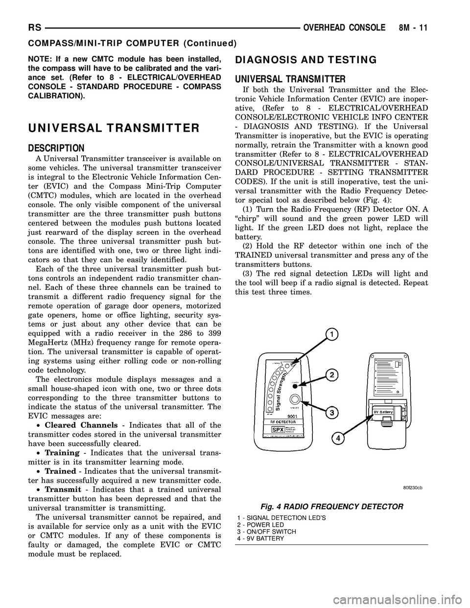
tor special tool as described below (Fig. 4):
(1) Turn the Radio Frequency (RF) Detector ON. A
ªchirpº will sound and the green power LED will
light. If the green LED does not light, replace the
battery.
(2) Hold the RF detector within one inch of the
TRAINED universal transmitter and press any of the
transmitters buttons.
(3) The red signal detection LEDs will light and
the tool will beep if a radio signal is detected. Repeat
this test three times.
Fig. 4 RADIO FREQUENCY DETECTOR
1 - SIGNAL DETECTION LED'S
2 - POWER LED
3 - ON/OFF SWITCH
4 - 9V BATTERY
RSOVERHEAD CONSOLE8M-11
COMPASS/MINI-TRIP COMPUTER (Continued)
Page 421 of 2339
STANDARD PROCEDURE
SETTING TRANSMITTER CODES
(1) Turn off the engine.
(2) Erase the codes by pressing the two outside
buttons. Release the buttons when the display con-
firms the operation (about 20 seconds).
(3) Choose one of the three buttons to train. Place
the hand-held transmitter within one inch of the uni-
versal transmitter and push the buttons on both
transmitters.
(4) Release both buttons. Your universal transmit-
ter is now ªtrainedº. To train the other buttons,
repeat Step 3 and Step 4. Be sure to keep your hand-
held transmitter in case you need to retrain the uni-
versal transmitter.
ERASING TRANSMITTER CODES
To erase the universal transmitter codes, simply
hold down the two outside buttons until the display
confirms the operation.
NOTE: Individual channels cannot be erased. Eras-
ing the transmitter codes will erase ALL pro-
grammed codes.
REMOVAL
(1) For the universal transmitter removal proce-
dure, (Refer to 8 - ELECTRICAL/OVERHEAD CON-
SOLE/COMPASS/MINI-TRIP COMPUTER -
REMOVAL.
AMBIENT TEMP SENSOR
DESCRIPTION
Ambient air temperature is monitored by the over-
head console through ambient temperature messages
received from the Powertrain Control Module (PCM)
over the Programmable Communications Interface
(PCI) data bus circuit. The PCM receives a hard
wired input from the ambient temperature sensor.
The ambient temperature sensor is a variable resis-
tor mounted to a bracket that is secured with a screw
to the right side of the headlamp mounting module
grille opening, behind the radiator grille and in front
of the engine compartment.
For additional information on the PCM, (Refer to 8
- ELECTRICAL/ELECTRONIC CONTROL MOD-
ULES/POWERTRAIN CONTROL MODULE -
DESCRIPTION).
OPERATION
The ambient temperature sensor is a variable
resistor that operates on a five-volt reference signal
sent by the Powertrain Control Module (PCM). The
resistance in the sensor changes as temperature
changes, changing the temperature sensor signal cir-
cuit voltage to the PCM. Based upon the resistance
in the sensor, the PCM senses a specific voltage on
the temperature sensor signal circuit, which it is pro-
grammed to correspond to a specific temperature.
The PCM then sends the proper ambient tempera-
ture messages to the Electronic Vehicle Information
Center (EVIC)/Compass Mini-Trip Computer (CMTC)
over the Programmable Communication Interface
(PCI) data bus.
The thermometer function is supported by the
ambient temperature sensor, a wiring circuit, the
PCM, the PCI data bus, and the Electronics module.
If any portion of the ambient temperature sensor cir-
cuit fails, the PCM will self-diagnose the circuit.
The ambient temperature sensor circuit can also be
diagnosed manually (Refer to 8 - ELECTRICAL/
OVERHEAD CONSOLE/AMBIENT TEMP SENSOR
- DIAGNOSIS AND TESTING - AMBIENT TEM-
PERATURE SENSOR CIRCUIT). If the temperature
sensor and circuit are confirmed to be OK, but the
temperature display is inoperative or incorrect,
(Refer to 8 - ELECTRICAL/OVERHEAD CONSOLE -
DIAGNOSIS AND TESTING) to determine the cause.
For complete circuit diagrams, refer to the appropri-
ate wiring information.
DIAGNOSIS AND TESTING
AMBIENT TEMPERATURE SENSOR
(1) Turn the ignition switch to the Off position.
Disconnect and isolate the battery negative cable.
Disconnect the ambient temperature sensor wire har-
ness connector.
(2) Measure the resistance of the ambient temper-
ature sensor. At room temperature (approx. 68ÉF),
the sensor resistance should be between 10-13 Kilo-
hms. The sensor resistance should be between these
two values at 68ÉF. If the resistance is out of range
replace the ambient temperature sensor.
AMBIENT TEMPERATURE SENSOR CIRCUIT
(1) Turn the ignition switch to the Off position.
Disconnect and isolate the battery negative cable.
Disconnect the ambient temperature sensor wire har-
ness connector and the Powertrain Control Module
(PCM) wire harness connector.
8M - 12 OVERHEAD CONSOLERS
UNIVERSAL TRANSMITTER (Continued)
Page 451 of 2339
AUTOMATIC DAY / NIGHT
MIRROR
DESCRIPTION
An automatic dimming inside day/night rear view
mirror and an automatic dimming driver side outside
rear view mirror are available factory-installed
options on this model. Following is a general descrip-
tion of this optional equipment.
The automatic day/night mirror is able to automat-
ically change its reflectance. A thin layer of electro-
chromic material between two pieces of conductive
glass make up the face of the mirror. Two photocell
sensors are used to monitor light levels and adjust
the reflectance of the mirror to reduce the glare of
headlamps approaching the vehicle from the rear.
For removal procedures, (Refer to 23 - BODY/IN-
TERIOR/REAR VIEW MIRROR - REMOVAL).
OPERATION
The ambient photocell sensor faces forward, to
detect the outside light levels. A second sensor faces
rearward to detect the light level received through
the vehicles back window. When the difference
between the two light levels becomes too great (the
light level received at the rear of the mirror is much
higher than that at the front of the mirror), the mir-
ror begins to darken.
The mirror switch allows the driver a manual con-
trol of whether the automatic dimming feature is
operational. When AUTO is selected a small Light-
Emitting Diode (LED), to the right of the mirror
switch, is illuminated. The automatic dimming fea-
ture will only operate when the ignition switch is in
the On position. The mirror also senses the backup
lamp circuit, and will automatically disable its self-
dimming feature whenever the transmission gear
selector is in the Reverse position.
NOTE: The mirror always defaults to an ON state
upon ignition.
The driver side automatic dimming mirror is stan-
dard with the automatic dimming inside mirror. The
signal to control the dimming of that mirror is gen-
erated by the automatic day/night inside rear view
mirror circuitry. That signal is then delivered to the
driver side outside rear view mirror on a hard wired
circuit.
The automatic day/night mirror cannot be
repaired. If faulty or damaged, the entire inside rear
view mirror assembly must be replaced.
DIAGNOSIS AND TESTING
AUTOMATIC DAY / NIGHT MIRROR
For circuit descriptions and diagrams, refer to the
appropriate wiring information. The wiring informa-
tion includes wiring diagrams, proper wire and con-
nector repair procedures, details of wire harness
routing and retention, connector pin-out information
and location views for the various wire harness con-
nectors, splices and grounds.
(1) Check the fuse in the intelligent power module.
If OK, go to Step 2. If not OK, repair the shorted cir-
cuit or component as required and replace the faulty
fuse.
(2) Turn the ignition switch to the On position.
Check for battery voltage at the fuse in the intelli-
gent power module. If OK, go to Step 3. If not OK,
repair the open circuit to the ignition switch as
required.
(3) Unplug the wire harness connector from the
automatic day/night mirror. Check for battery voltage
at the fused ignition switch output circuit cavity of
the automatic day/night mirror wire harness connec-
tor. If OK, go to Step 4. If not OK, repair the open
circuit to the junction block as required.
(4) Turn the ignition switch to the Off position.
Check for continuity between the ground circuit cav-
ity of the automatic day/night mirror wire harness
connector and a good ground. There should be conti-
nuity. If OK, go to Step 5. If not OK, repair the cir-
cuit to ground as required.
(5) Turn the ignition switch to the On position. Set
the parking brake. Place the transmission gear selec-
tor lever in the Reverse position. Check for battery
voltage at the backup lamp switch output circuit cav-
ity of the automatic day/night mirror wire harness
connector. If voltage is present, reinstall the auto-
matic day/night mirror wire harness connector and
go to Step 6. If not OK, repair the open circuit as
required.
(6) Place the transmission gear selector lever in
the Neutral position. Place the automatic day/night
mirror switch in the On (LED in the switch is
lighted) position. Cover the forward facing ambient
photocell sensor to keep out any ambient light.
NOTE: The ambient photocell sensor must be cov-
ered completely, so that no light reaches the sen-
sor. Use a finger pressed tightly against the sensor,
or cover the sensor completely with electrical tape.
(7) Shine a light into the rearward facing head-
lamp photocell sensor. The automatic day/night mir-
ror should darken. The automatic day/night mirror
should darken within 2 minutes if testing for the
first time. For immediate response, turn the vehicle
8N - 28 POWER MIRRORSRS
Page 455 of 2339

(Refer to 8 - ELECTRICAL/HEATED SEATS -
DESCRIPTION) for more information on the heated
seat option. (Refer to 8 - ELECTRICAL/POWER
SEATS - DESCRIPTION - MEMORY SEAT SYS-
TEM) for more information on the memory seat sys-
tem.
The power seat system includes the following com-
ponents:
²Power seat recliners
²Power seat switches
²Power seat tracks
²Circuit breaker
The power seat system with memory and heated
seat options includes the following components:
²Power seat recliner
²Power seat switch
²Power seat track.
²Memory Seat Mirror Module (MSMM)
²Memory set switch
²Heated Seat Module (HSM)
²Heated seat switch
²Electronic Vehicle Information Center (EVIC)
MEMORY SYSTEM
The memory system is able to store and recall the
driver side power seat positions (including the power
recliner position), power adjustable pedal positions
and the driver outside mirror position for two driv-
ers. On vehicles equipped with a factory radio, the
memory system is also able to store and recall radio
station presets for two drivers. The memory system
also will store and recall the last station listened to
for each driver, even if it is not one of the preset sta-
tions.
The memory system will automatically return to
its preset settings when the corresponding numbered
button of the memory switch is depressed, or when
the doors are unlocked using the corresponding
Remote Keyless Entry (RKE) transmitter. A customer
programmable feature of the memory system allows
the RKE recall of memory features to be disabled, if
desired. This programmable feature is internal in the
Electronic Vehicle Information Center (EVIC) mod-
ule, which is located in the overhead console.
A Memory Seat Mirror Module (MSMM) is used to
control and integrate the many electronic functions
and features included in the memory seat and mirror
systems.
The memory system includes the following compo-
nents:
²Memory Seat Mirror Module (MSMM)
²Memory set switch
²Position potentiometers on the driver outside
side view mirror
²Position potentiometers on the power adjustable
pedal motor²Position potentiometers on the driver side power
seat track and power seat recliner motors
²Electronic Vehicle Information Center (EVIC)
²Radio receiver (if PCI data bus capable)
Certain functions of the memory system rely upon
resources shared with other electronic modules in the
vehicle over the Programmable Communications
Interface (PCI) data bus network. Initial diagnosis of
these electronic modules or the PCI data bus network
requires the use of a DRBIIItor equivalent scan tool
and the proper Diagnostic Procedures information. If
this method does not prove conclusive, the proper
wiring schematics and the service manual diagnostic
information are required.
The other electronic modules that may affect mem-
ory system operation are:
²Body Control Module (BCM)- (Refer to 8 -
ELECTRICAL/ELECTRONIC CONTROL MOD-
ULES/BODY CONTROL/CENTRAL TIMER MODUL
- DESCRIPTION) for additional information.
²Powertrain Control Module (PCM)- (Refer
to 8 - ELECTRICAL/ELECTRONIC CONTROL
MODULES/POWERTRAIN CONTROL MODULE -
DESCRIPTION) for additional information.
²Transmission Control Module (TCM)- (Refer
to 8 - ELECTRICAL/ELECTRONIC CONTROL
MODULES/TRANSMISSION CONTROL MODULE -
DESCRIPTION) for additional information.
(Refer to 8 - ELECTRICAL/HEATED SEATS -
DESCRIPTION) for additional information on the
heated seat system. (Refer to 8 - ELECTRICAL/
POWER LOCKS - DESCRIPTION) for additional
information on the RKE system.
OPERATION
POWER SEAT SYSTEM
The power seat system receives battery current
through fuse #22 in the Integrated Power Module
(IPM) and a circuit breaker under the front seats,
regardless of the ignition switch position.
When a power seat switch control knob or knobs
are actuated, a battery feed and a ground path are
applied through the switch contacts to the appropri-
ate power seat track adjuster motor. The selected
adjuster motor operates to move the seat track
through its drive unit in the selected direction until
the switch is released, or until the travel limit of the
seat track is reached. When the switch is moved in
the opposite direction, the battery feed and ground
path to the motor are reversed through the switch
contacts. This causes the adjuster motor to run in the
opposite direction.
No power seat switch should be held applied in any
direction after the seat track has reached its travel
limit. The power seat adjuster motor each contain a
8N - 32 POWER SEAT SYSTEMRS
POWER SEAT SYSTEM (Continued)