ESP CHRYSLER CARAVAN 2005 Owner's Guide
[x] Cancel search | Manufacturer: CHRYSLER, Model Year: 2005, Model line: CARAVAN, Model: CHRYSLER CARAVAN 2005Pages: 2339, PDF Size: 59.69 MB
Page 456 of 2339
self-resetting circuit breaker to protect them from
overload. However, consecutive or frequent resetting
of the circuit breaker must not be allowed to con-
tinue, or the motor may be damaged.
MEMORY SYSTEM
The Memory Seat Mirror Module (MSMM) receives
battery current through fuse #22 in the Integrated
Power Module (IPM) and the power seat system cir-
cuit breaker, located under the driver side front seat
near the rear edge of the seat cushion pan. The mem-
ory system does not operate with the Ignition-Off
Draw (IOD) fuse removed. The MSMM will drive a
maximum of 2 motors at a time in a given direction.
If conflicting directions are requested, the priority for
response will be approximately as follows:
²Seat Track Rearward or Forward
²Seat Front Down or Up
²Seat Rear Down or Up
²Recliner Rearward or Forward
The inputs from these switches to the MSMM is a
current limited battery source fed by the MSMM.
This protects the MSMM printed circuit board traces
from acting as fuses. All of these switch contact
inputs to the MSMM are normally closed to ground,
except when actuated.
For diagnosis of the MSMM, the Programmable
Communication Interface (PCI) data bus, or the other
electronic modules on the PCI data bus that provide
inputs and outputs for the memory system, the use of
a DRBIIItor equivalent scan tool and the proper
Diagnostic Procedures information is recommended.
ELECTRONIC VEHICLE INFORMATION CENTER
The Electronic Vehicle Information Center (EVIC)
serves as the user interface for the memory system.
It displays memory system status messages and pro-
vides the user with the means for enabling and dis-
abling the many customer programmable features
available on the vehicle, including those for the mem-
ory system.
(Refer to 8 - ELECTRICAL/OVERHEAD CON-
SOLE/ELECTRONIC VEHICLE INFO CENTER -
DESCRIPTION) for additional information on the
EVIC.
DIAGNOSIS AND TESTING
POWER SEAT SYSTEM
Following are tests that will help to diagnose the
hard wired components and circuits of the power seat
system. However, if the vehicle is also equipped with
the optional memory system, these tests may not
prove conclusive in the diagnosis of the driver side
power seat. In order to obtain conclusive testing ofthe driver side power seat with the memory system
option, the Programmable Communications Interface
(PCI) data bus network and all of the electronic mod-
ules that provide inputs to, or receive outputs from
the memory system components must be checked,
(Refer to 8 - ELECTRICAL/POWER SEATS - DIAG-
NOSIS AND TESTING).
WARNING: SOME VEHICLES ARE EQUIPPED WITH
SEATBACK MOUNTED AIRBAGS. BEFORE
ATTEMPTING TO DIAGNOSE OR SERVICE ANY
SEAT OR POWER SEAT SYSTEM COMPONENT
YOU MUST FIRST DISCONNECT AND ISOLATE THE
BATTERY NEGATIVE CABLE. THEN WAIT TWO MIN-
UTES FOR THE SYSTEM CAPACITOR TO DIS-
CHARGE BEFORE FURTHER SYSTEM SERVICE.
THIS IS THE ONLY SURE WAY TO DISABLE THE
AIRBAG SYSTEM. FAILURE TO DO SO COULD
RESULT IN ACCIDENTAL AIRBAG DEPLOYMENT
AND POSSIBLE PERSONAL INJURY.
(1) If either power seat is completely inoperable,
check the power seat circuit breaker, located under
the trailing edge of the driver side power seat. If the
power seat circuit breaker is OK, continue to the
next step.
(2) Check for proper battery and ground connec-
tions at the power seat switch and/or memory seat
module. Repair any wiring as necessary.
(3) Check the power seat system wire harness con-
nections and pins to ensure proper circuit continuity
and ground paths.
MEMORY SYSTEM
In order to obtain conclusive testing of the memory
system, the Programmable Communications Interface
(PCI) data bus network and all of the electronic mod-
ules that provide inputs to, or receive outputs from
the memory system components must be checked.
The most reliable, efficient, and accurate means to
diagnose the driver side power seat with the memory
system option requires the use of a DRBIIItor
equivalent scan tool and the proper Diagnostic Proce-
dures information. The DRBIIItscan tool can pro-
vide confirmation that the PCI data bus is functional,
that all of the electronic modules are sending and
receiving the proper messages on the PCI data bus,
and that the memory system is receiving the proper
hard wired inputs and relaying the proper hard
wired outputs to perform its driver side power seat
functions.
(1) If the driver power seat exhibits an interrupted
or jerky motion, ensure the wire harness is connected
correctly. To verify the concern, obtain a DRB IIItor
equivalent scan tool and energize each axis one at a
time. If any axis stops in approximately 2 seconds
(without hitting the end of travel), the feedback for
RSPOWER SEAT SYSTEM8N-33
POWER SEAT SYSTEM (Continued)
Page 464 of 2339
travel. This allows the power sliding door to stop and
reverse direction any time an obstruction is felt or
any of the command switches are operated (while
closing only). Battery voltage is supplied to the power
sliding door system through a 40 amp fuse, located in
the Integrated Power Module (IPM) assembly. The
child lockout switch prevents children from opening
or actuating the power sliding door system when
desired. In the unlikely event that the power sliding
door system develops a fault, the power sliding door
can still be operated manually from the interior or
exterior door handle, just like a standard manual
sliding door.
The power sliding door control module communi-
cates on the Programmable Communication Interface
(PCI) Data Bus Circuit. Therefore, the power sliding
door control module can generate and store its own
Diagnostic Trouble Codes (DTC). A diagnostic scan
tool, such as the DRB IIItis used to read and diag-
nose these trouble codes.
NOTE: It may be possible to generate Sliding Door
Diagnostic Trouble Codes during normal power
sliding door operation. Refer to the Body Diagnos-
tic Manual for a complete list of diagnostic routines.
For additional information, (Refer to 8 - ELECTRI-
CAL/POWER DOORS - OPERATION). Refer to the
appropriate wiring information for complete circuit
schematic or connector pin-out information.WARNING: BE CERTAIN TO READ ALL WARNINGS
AND CAUTIONS IN POWER SLIDING DOOR OPER-
ATION BEFORE ATTEMPTING ANY SERVICE OF
THE POWER SLIDING DOOR SYSTEM OR COMPO-
NENTS.
OPERATION
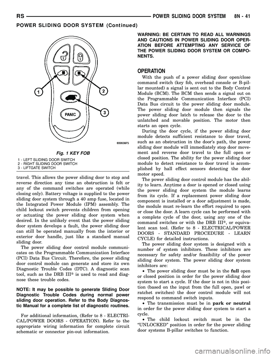
With the push of a power sliding door open/close
command switch (key fob, overhead console or B-pil-
lar mounted) a signal is sent out to the Body Control
Module (BCM). The BCM then sends a signal out on
the Programmable Communication Interface (PCI)
Data Bus circuit to the power sliding door module.
The power sliding door module then signals the
power sliding door latch to release the door to the
unlatched and movable position. The motor then
starts an open cycle.
During the door cycle, if the power sliding door
module detects sufficient resistance to door travel,
such as an obstruction in the door's path, the power
sliding door module will immediately stop door move-
ment and reverse door travel to the full open or
closed position. The ability for the power sliding door
module to detect resistance to door travel is accom-
plished by hall effect sensors detecting the door
motor speed.
The power sliding door control module has the abil-
ity to learn. Anytime a door is opened or closed using
the power sliding door system the module learns
from its cycle. If a replacement power sliding door
component is installed or a door adjustment is made,
the module must re-learn the effort required to open
or close the door. A learn cycle can be performed with
a complete cycle of the door, using any one of the
command switches or with the DRB IIIt, or equiva-
lent scan tool. (Refer to 8 - ELECTRICAL/POWER
DOORS - STANDARD PROCEDURE - LEARN
CYCLE) for detailed instructions.
The power sliding door system is designed with a
number of system inhibitors. These inhibitors are
necessary for safety and/or feasibility of the power
sliding door system. The power sliding door system
inhibitors are:
²The power sliding door must be in thefullopen
or closed position in order for the power sliding door
system to start a cycle. If the door is not in this posi-
tion (based on the input from the full open, pawl or
ratchet switches) the door control module will not
respond to command switch inputs.
²The transmission must be inpark or neutral
in order for the power sliding door system to start a
cycle.
²The child lockout switch must be in the
ªUNLOCKEDº position in order for the power sliding
door systems B-pillar switches to function.
Fig. 1 KEY FOB
1 - LEFT SLIDING DOOR SWITCH
2 - RIGHT SLIDING DOOR SWITCH
3 - LIFTGATE SWITCH
RSPOWER SLIDING DOOR SYSTEM8N-41
POWER SLIDING DOOR SYSTEM (Continued)
Page 475 of 2339
NOTE: Push in on the push-pins at the clutch hous-
ing (plastic side) until you hear one click. Push in
on the push-pin fasteners at the motor mount
(sheet metal side) until you hear two clicks. This
assures proper installation/attachment of the motor
to the sliding door.
(3) Install the flex shaft by lining up the square
shaped drive shaft with the corresponding hole in the
door motor drive unit and push straight in.
(4) Install the E-clip to secure flex-shaft.
(5) Install the weather shield as necessary.
(6) Install the door trim panel on the sliding door,
(Refer to 23 - BODY/DOORS - SLIDING/TRIM
PANEL - INSTALLATION) for the procedure.
(7) Connect the battery negative cable.
FULL OPEN SWITCH
DESCRIPTION
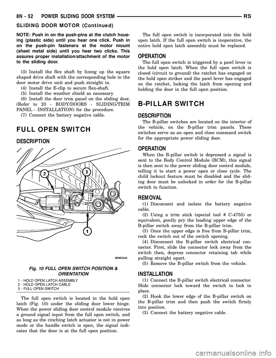
The full open switch is located in the hold open
latch (Fig. 10) under the sliding door lower hinge.
When the power sliding door control module receives
a ground signal input from the full open switch, and
as long as the cinching latch actuator is not in power
mode or the handle switch is open, the signal indi-
cates that the door is at the full open position.The full open switch is incorporated into the hold
open latch. If the full open switch is inoperative, the
entire hold open latch assembly must be replaced.
OPERATION
The full open switch is triggered by a pawl lever in
the hold open latch. When the full open switch is
closed (circuit to ground) the ratchet has engaged on
the hold open striker and the pawl lever has engaged
on the ratchet, locking the latch from opening and
holding the door in the full open position.
B-PILLAR SWITCH
DESCRIPTION
The B-pillar switches are located on the interior of
the vehicle, on the B-pillar trim panels. These
switches serve as an open and close command switch
for the appropriate power sliding door.
OPERATION
When the B-pillar switch is depressed a signal is
sent to the Body Control Module (BCM), this signal
is then sent to the power sliding door control module,
telling it to start a power open or close cycle. The
child lockout feature must be disabled and the slid-
ing door must be unlocked in order for the B-pillar
switch to function.
REMOVAL
(1) Disconnect and isolate the battery negative
cable.
(2) Using a trim stick (special tool # C-4755) or
equivalent, gently pry the leading upper edge of the
B-pillar switch away from the B-pillar trim.
(3) Once the upper edge is free from B-pillar trim,
rock the switch out of the switch opening.
(4) Disconnect the B-pillar switch electrical con-
nector. First, slide the connector lock away from the
switch then, depress connector retaining tab while
pulling straight apart.
(5) Remove the B-pillar switch from the vehicle.
INSTALLATION
(1) Connect the B-pillar switch electrical connector.
Slide connector lock toward the switch to lock in
place.
(2) Hook the lower edge of the B-pillar switch on
the B-pillar trim and then push the switch firmly
into position.
(3) Connect the battery negative cable.
Fig. 10 FULL OPEN SWITCH POSITION &
ORIENTATION
1 - HOLD OPEN LATCH ASSEMBLY
2 - HOLD OPEN LATCH CABLE
3 - FULL OPEN SWITCH
8N - 52 POWER SLIDING DOOR SYSTEMRS
SLIDING DOOR MOTOR (Continued)
Page 497 of 2339
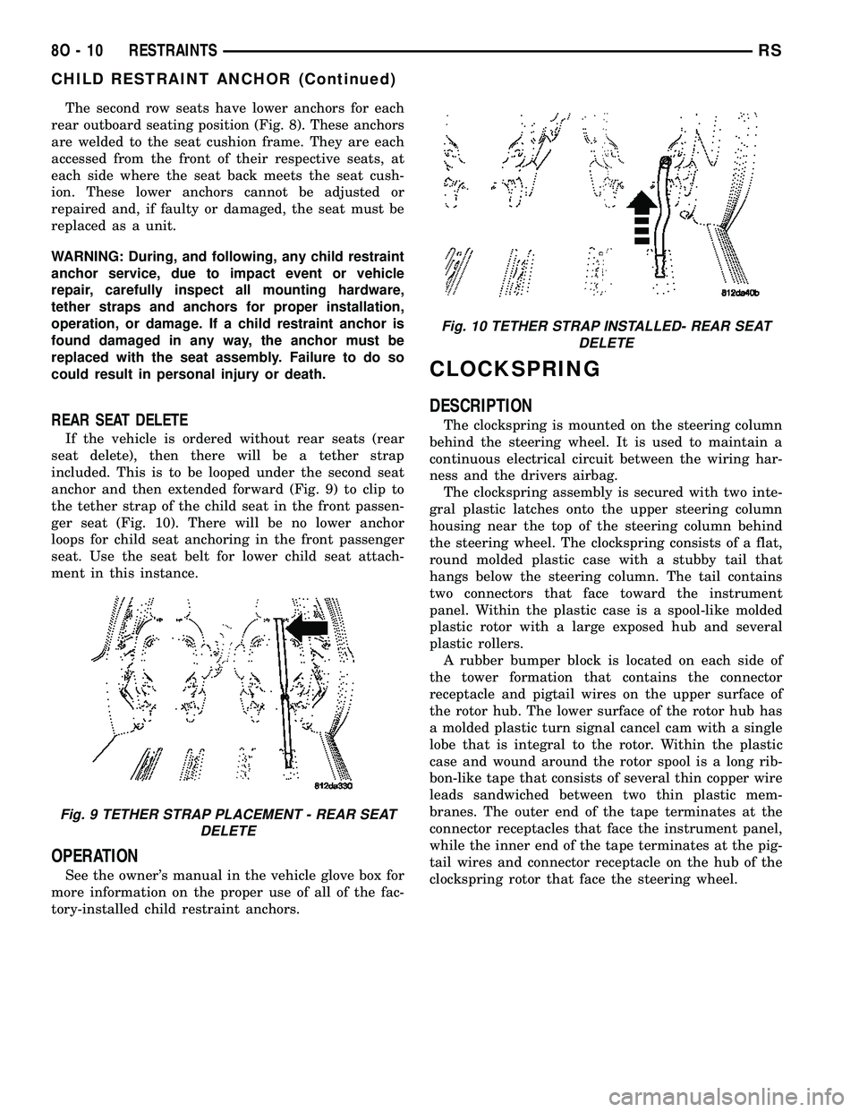
The second row seats have lower anchors for each
rear outboard seating position (Fig. 8). These anchors
are welded to the seat cushion frame. They are each
accessed from the front of their respective seats, at
each side where the seat back meets the seat cush-
ion. These lower anchors cannot be adjusted or
repaired and, if faulty or damaged, the seat must be
replaced as a unit.
WARNING: During, and following, any child restraint
anchor service, due to impact event or vehicle
repair, carefully inspect all mounting hardware,
tether straps and anchors for proper installation,
operation, or damage. If a child restraint anchor is
found damaged in any way, the anchor must be
replaced with the seat assembly. Failure to do so
could result in personal injury or death.
REAR SEAT DELETE
If the vehicle is ordered without rear seats (rear
seat delete), then there will be a tether strap
included. This is to be looped under the second seat
anchor and then extended forward (Fig. 9) to clip to
the tether strap of the child seat in the front passen-
ger seat (Fig. 10). There will be no lower anchor
loops for child seat anchoring in the front passenger
seat. Use the seat belt for lower child seat attach-
ment in this instance.
OPERATION
See the owner's manual in the vehicle glove box for
more information on the proper use of all of the fac-
tory-installed child restraint anchors.
CLOCKSPRING
DESCRIPTION
The clockspring is mounted on the steering column
behind the steering wheel. It is used to maintain a
continuous electrical circuit between the wiring har-
ness and the drivers airbag.
The clockspring assembly is secured with two inte-
gral plastic latches onto the upper steering column
housing near the top of the steering column behind
the steering wheel. The clockspring consists of a flat,
round molded plastic case with a stubby tail that
hangs below the steering column. The tail contains
two connectors that face toward the instrument
panel. Within the plastic case is a spool-like molded
plastic rotor with a large exposed hub and several
plastic rollers.
A rubber bumper block is located on each side of
the tower formation that contains the connector
receptacle and pigtail wires on the upper surface of
the rotor hub. The lower surface of the rotor hub has
a molded plastic turn signal cancel cam with a single
lobe that is integral to the rotor. Within the plastic
case and wound around the rotor spool is a long rib-
bon-like tape that consists of several thin copper wire
leads sandwiched between two thin plastic mem-
branes. The outer end of the tape terminates at the
connector receptacles that face the instrument panel,
while the inner end of the tape terminates at the pig-
tail wires and connector receptacle on the hub of the
clockspring rotor that face the steering wheel.
Fig. 9 TETHER STRAP PLACEMENT - REAR SEAT
DELETE
Fig. 10 TETHER STRAP INSTALLED- REAR SEAT
DELETE
8O - 10 RESTRAINTSRS
CHILD RESTRAINT ANCHOR (Continued)
Page 530 of 2339
SEAT BELT TENSIONER
DESCRIPTION
The seat belt system incorporates Seat Belt Ten-
sioners. The tensioner is designed to hold the occu-
pant in their respective seat by retracting the seat
belt up to four inches. They are integral to the front
seat belt buckles and cannot be serviced. If found
defective they must be replaced. After an airbag
deployment, the tensioner must be replaced.
Seat Belt Tensioners supplement the dual front air-
bag system. The seat belt tensioners are integral to
the front seat belt buckles, which are secured to the
seat cushion frame on the inboard side. The seat belt
tensioners are controlled by the Occupant Restraint
Controller (ORC) and are connected to the vehicle
electrical system through the body wire harness.
The seat belt tensioners cannot be repaired and, if
faulty or damaged, the entire front seat belt buckle
must be replaced. The seat belt tensioners are not
intended for reuse and must be replaced following
any front airbag deployment.
OPERATION
WARNING: When the front airbag is deployed, the
tensioner will have deployed also and should be
replaced. Failure to do so could result in occupant
personal injury or death.
The seat belt tensioners are deployed by a signal
generated by the Occupant Restraint Controller
(ORC) through the driver or passenger seat belt ten-
sioner line 1 and line 2 (or squib) circuits. When the
ORC sends the proper electrical signal to the tension-
ers, the electrical energy generates enough heat to
initiate a small pyrotechnic gas generator.
Removing excess slack from the front seat belts not
only keeps the occupants properly positioned for an
airbag deployment following a frontal impact of the
vehicle, but also helps to reduce injuries that the
occupants of the front seat might experience in these
situations as a result of a harmful contact with the
steering wheel, steering column, instrument panel
and/or windshield.
The ORC monitors the condition of the seat belt
tensioners through circuit resistance, and will illumi-
nate the airbag indicator in the ElectroMechanical
Instrument Cluster (EMIC) and store a Diagnostic
Trouble Code (DTC) for any fault that is detected.
For proper diagnosis of the seat belt tensioners, use a
scan tool and the appropriate diagnostic information.
SEAT WEIGHT BLADDER &
PRESSURE SENSOR
DESCRIPTION
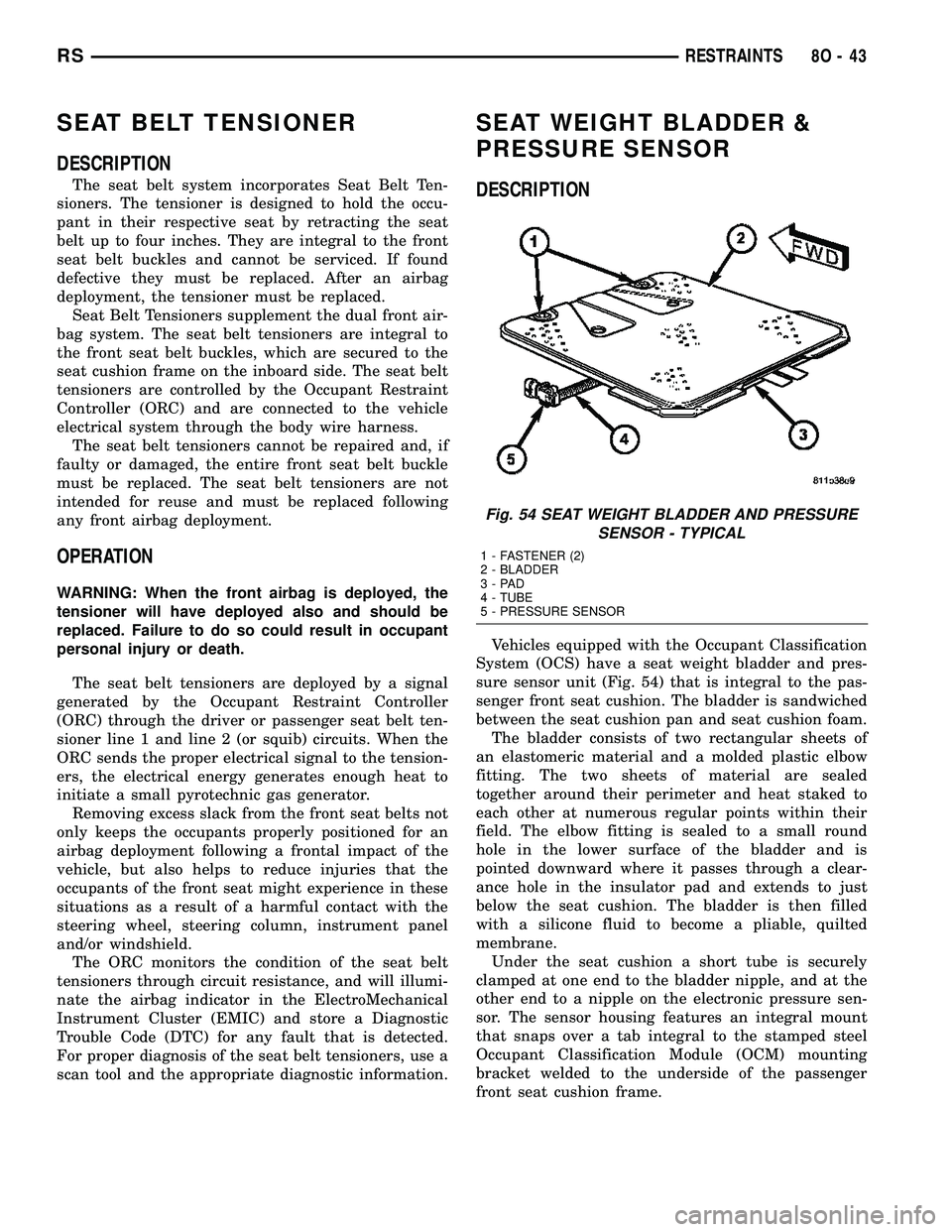
Vehicles equipped with the Occupant Classification
System (OCS) have a seat weight bladder and pres-
sure sensor unit (Fig. 54) that is integral to the pas-
senger front seat cushion. The bladder is sandwiched
between the seat cushion pan and seat cushion foam.
The bladder consists of two rectangular sheets of
an elastomeric material and a molded plastic elbow
fitting. The two sheets of material are sealed
together around their perimeter and heat staked to
each other at numerous regular points within their
field. The elbow fitting is sealed to a small round
hole in the lower surface of the bladder and is
pointed downward where it passes through a clear-
ance hole in the insulator pad and extends to just
below the seat cushion. The bladder is then filled
with a silicone fluid to become a pliable, quilted
membrane.
Under the seat cushion a short tube is securely
clamped at one end to the bladder nipple, and at the
other end to a nipple on the electronic pressure sen-
sor. The sensor housing features an integral mount
that snaps over a tab integral to the stamped steel
Occupant Classification Module (OCM) mounting
bracket welded to the underside of the passenger
front seat cushion frame.
Fig. 54 SEAT WEIGHT BLADDER AND PRESSURE
SENSOR - TYPICAL
1 - FASTENER (2)
2 - BLADDER
3-PAD
4 - TUBE
5 - PRESSURE SENSOR
RSRESTRAINTS8O-43
Page 534 of 2339
OPERATION
The PCM on NGC vehicles first senses that the
speed control is set. If the set speed is exceeded by
more than 4 mph (6.5 km/hr) and the throttle is
closed, the PCM on NGC vehicles causes the trans-
axle to downshift to THIRD gear. After downshifting,
the automatic speed control resumes normal opera-
tion. To ensure that an upshift is appropriate after
the set speed is reached, the PCM on NGC vehicles
waits until the speed control system opens the throt-
tle at least 6 degrees before upshifting to OVER-
DRIVE again.
If the driver applies the brakes, canceling auto-
matic speed control operation with the transaxle still
in THIRD gear, the PCM on NGC vehicles maintains
this gear until the driver opens the throttle at least 6
degrees to avoid an inappropriate upshift. The
upshift is also delayed for 2.5 seconds after reaching
the 6 degrees throttle opening in anticipation that
the driver might open the throttle enough to require
THIRD gear. This will avoid unnecessary and dis-
turbing transmission cycling. If the automatic speed
control RESUME feature is used after braking, the
upshift is delayed until the set speed is achieved to
reduce cycling and provide better response.
DIAGNOSIS AND TESTING - ROAD TEST
Perform a vehicle road test to verify reports of
speed control system malfunction. The road test
should include attention to the speedometer. Speed-
ometer operation should be smooth and without flut-
ter at all speeds.Flutter in the speedometer indicates a problem
which might cause surging in the speed control sys-
tem. The cause of any speedometer problems should
be corrected before proceeding. Refer to the Instru-
ment Cluster for speedometer diagnosis.
If a road test verifies an inoperative system, and
the speedometer operates properly, check for:
²A Diagnostic Trouble Code (DTC). If a DTC
exists, conduct tests per the Powertrain Diagnostic
Procedures manual.
²A misadjusted brake (stop) lamp switch. This
could also cause an intermittent problem.
²Loose or corroded electrical connections at the
servo. Corrosion should be removed from electrical
terminals and a light coating of Mopar Multipurpose
Grease, or equivalent, applied.
²Leaking vacuum reservoir.
²Loose or leaking vacuum hoses or connections.
²Defective one-way vacuum check valve.
²Secure attachment at both ends of the speed
control servo cable.
²Smooth operation of throttle linkage and throttle
body air valve.
²Conduct electrical test at PCM.
²Failed speed control servo. Do the servo vacuum
test.
CAUTION: When test probing for voltage or conti-
nuity at electrical connectors, care must be taken
not to damage connector, terminals or seals. If
these components are damaged, intermittent or
complete system failure may occur.
SPECIFICATIONS - TORQUE
DESCRIPTION N´m Ft. Lbs. In. Lbs.
Servo Mounting Bracket
Nuts14 10.3 123.9
Servo Mounting Bracket
Bolts14 10.3 123.9
Servo Mounting Nuts 6.7 60
RSSPEED CONTROL8P-3
SPEED CONTROL (Continued)
Page 535 of 2339
CABLE
DESCRIPTION
The speed control servo cable is connected between
the speed control vacuum servo diaphragm and the
throttle body control linkage.
OPERATION
This cable causes the throttle control linkage to
open or close the throttle valve in response to move-
ment of the vacuum servo diaphragm.
REMOVAL
(1) Disconnect the negative battery cable.
(2) Remove speed control cable from throttle cam
by sliding clasp out hole used for throttle cable.
(3) Compress the retaining tabs on the cable and
slide cable out of bracket.
(4) Disconnect electrical connectors and vacuum
hose from servo.
(5) Remove two nuts attaching speed control cable
and mounting bracket to servo.
(6) Pull cable away from servo to expose retaining
clip and remove clip attaching cable to servo.
(7) Remove speed control cable.
INSTALLATION
(1) Slide cable into throttle cable bracket and
engage retaining tabs.
(2) Rotate the throttle cam forward to the wide
open position and install speed control cable clasp.
(3) Rotate the throttle cam forward to the wide
open position and install throttle cable clasp.
(4) Install retaining clip that attaches cable to
servo.
(5) Insert servo studs through holes in the mount-
ing bracket and speed control cable.
(6) Install nuts, tighten to 6.7 N´m (60 in. lbs.).
(7) Connect vacuum hose to servo.
(8) Connect electrical connector.
(9) Install servo and bracket and tighten nuts and
bolt.
(10) Connect negative battery cable.
SERVO
DESCRIPTION
The servo unit consists of a solenoid valve body,
and a vacuum chamber. The solenoid valve body con-
tains three solenoids:
²Vacuum
²Vent
²Dump
The vacuum chamber contains a diaphragm with a
cable attached to control the throttle linkage.
OPERATION
The PCM controls the solenoid valve body. The
solenoid valve body controls the application and
release of vacuum to the diaphragm of the vacuum
servo. The servo unit cannot be repaired and is ser-
viced only as a complete assembly.
Power is supplied to the servo by the PCM through
the brake switch. The PCM controls the ground path
for the vacuum and vent solenoids.
The dump solenoid is energized anytime it receives
power. If power to the dump solenoid is interrupted,
the solenoid dumps vacuum in the servo. This pro-
vides a safety backup to the vent and vacuum sole-
noids.
The vacuum and vent solenoids must be grounded
by the PCM to operate. When the PCM grounds the
vacuum servo solenoid, the solenoid allows vacuum
to enter the servo and pull open the throttle plate
using the cable. When the PCM breaks the ground,
the solenoid closes and no more vacuum is allowed to
enter the servo. The PCM also operates the vent sole-
noid via ground. The vent solenoid opens and closes a
passage to bleed or hold vacuum in the servo as
required.
The PCM cycles the vacuum and vent solenoids to
maintain the set speed, or to accelerate and deceler-
ate the vehicle. To increase throttle opening, the
PCM grounds the vacuum and vent solenoids. To
decrease throttle opening, the PCM removes the
grounds from the vacuum and vent solenoids.
REMOVAL
(1) Release hood latch and open hood.
(2) Disconnect the negative battery cable.
(3) Disconnect the throttle and speed control cable
ends from throttle body (Fig. 2).
(4) Depress lock tabs holding speed control and
throttle cable casing to cable mount bracket.
(5) Disconnect vacuum line from speed control
servo that leads to the battery tray/vacuum reservoir.
(6) Remove battery tray/vacuum reservoir, refer to
the Battery section for more information (Fig. 3).
(7) Remove speed control servo and bracket (Fig.
4).
(8) Disconnect wire connector from speed control
servo.
(9) Remove speed control servo.
INSTALLATION
Transfer speed control cable to replacement speed
control servo.
(1) Install retaining clip to cable at servo.
(2) Install 2 nuts at cable to servo and servo
bracket, tighten to 7 N´m (60 ins. lbs.).
(3) Connect electrical connector to servo.
8P - 4 SPEED CONTROLRS
Page 542 of 2339
When the ignition switch is moved to the RUN
position, the SKREEM transmits an Radio Frequency
(RF) signal to the transponder in the ignition key.
The SKREEM then waits for a response RF signal
from the transponder in the key. If the response
received identifies the key as valid, the SKREEM
sends a9valid key9message to the Powertrain Con-
trol Module (PCM) over the Programmable Commu-
nication Interface (PCI) data bus. If the response
received identifies the key as invalid or no response
is received from the transponder in the ignition key,
the SKREEM sends an9invalid key9message to the
PCM. The PCM will enable or disable engine opera-
tion based upon the status of the SKREEM mes-
sages. It is important to note that the default
condition in the PCM is9invalid key.9Therefore, if no
response is received by the PCM, the engine will be
immobilized after two (2) seconds of running.
The SKREEM also sends indicator light status
messages to the Mechanical Instrument Cluster
(MIC) to operate the light. This is the method used to
turn the light ON solid or to flash it after the indi-
cator light test is complete to signify a fault in the
SKREES. If the light comes ON and stays ON solid
after the indicator light test, this signifies that the
SKREEM has detected a system malfunction and/or
that the SKREES has become inoperative. If the
SKREEM detects an invalid keyORa key-related
fault exists, the indicator light will flash following
the indicator light test. The SKREEM may also
request an audible chime if the customer key pro-
gramming feature is available and the procedure is
being utilized (Refer to 8 - ELECTRICAL/VEHICLE
THEFT SECURITY/TRANSPONDER KEY - STAN-
DARD PROCEDURE).
REMOTE KEYLESS ENTRY (RKE)
After pressing the lock button on the RKE trans-
mitter, all of the door locks will lock, the illuminated
entry will turn off (providing all doors are closed),
and the VTSS (if equipped) will arm. After pressing
the unlock button, on the RKE transmitter, one time,
the driver door lock will unlock, the illuminated
entry will turn on the courtesy lamps, and the VTSS
(if equipped) will disarm. After pressing the unlock
button a second time, the remaining door locks will
unlock. The Electronic Vehicle Information Center
(EVIC) or the DRBIIItscan tool can reprogram this
feature to unlock all of the door locks with one press
of the unlock button. If the vehicle is equipped with
the memory system, the memory message will iden-
tify which transmitter (1 or 2) sent the signal.The SKREEM is capable of retaining up to 8 indi-
vidual access codes (8 transmitters). If the PRNDL is
in any position except park, the SKREEM will dis-
able the RKE. The 4 button transmitter uses
1-CR2032 battery. The minimum battery life is
approximately 4.7 years based on 20 transmissions a
day at 84ÉF (25ÉC). Use the DRBIIItscan tool or the
Miller Tool 9001 RF Detector to test the RKE trans-
mitter. Use the DRBIIItor the customer program-
ming method to program the RKE system. However,
the SKREEM will only allow RKE programming
when the ignition is in the ON position, the PRNDL
is in park position, and the VTSS (if equipped) is dis-
armed.
TIRE PRESSURE MONITORING (TPM)
The SKREEM monitors the signals from the tire
pressure sensor/transmitters and determines if any
tire has gone below the low pressure threshold LOW
TIRE PRESSURE THRESHOLDS table.
LOW TIRE PRESSURE THRESHOLDS
SYSTEM STATUS
INDICATORTIRE PRESSURE
ON 193 kPa (28 PSI)
OFF 227 kPa (33 PSI)
CRITICAL AND NON-CRITICAL SYSTEM ALERTS
CRITICAL:A critical alert will be triggered when
a tire pressure has gone below a set threshold pres-
sure. The EVIC display will display ªX TIRE(S) LOW
PRESSUREº. ªXº will be the number of tires report-
ing low pressure. The message will display for the
duration of the current ignition cycle or until an
EVIC button is pressed. If the display is removed
without correcting the condition, it will reappear 300
seconds to warn the driver of the low pressure condi-
tion.
NON-CRITICAL:A non-critical alert will be trig-
gered when no signal is received from a sensor/trans-
mitter. The EVIC display in the cluster will display
ªSERVICE TIRE SYSTEM SOON.º
DIAGNOSIS AND TESTING - SENTRY KEY
REMOTE ENTRY MODULE
For proper diagnosis and testing of the Sentry Key
Remote Entry Module (SKREEM), use a DRBllltand
refer to the proper Body Diagnostic Procedures infor-
mation.
RSVEHICLE THEFT SECURITY8Q-5
SENTRY KEY REMOTE ENTRY MODULE (Continued)
Page 572 of 2339
DESCRIPTION - CONNECTOR, GROUND AND
SPLICE INFORMATION
CAUTION: Not all connectors are serviced. Some
connectors are serviced only with a harness. A typ-
ical example might be the Supplemental Restraint
System connectors. Always check parts availability
before attempting a repair.
IDENTIFICATION
In-line connectors are identified by a number, as
follows:
²In-line connectors located in the engine compart-
ment are C100 series numbers
²In-line connectors located in the Instrument
Panel area are C200 series numbers.
²In-line connectors located in the body are C300
series numbers.
²Jumper harness connectors are C400 series
numbers.
²Grounds and ground connectors are identified
with a ªGº and follow the same series numbering as
the in-line connectors.
²Splices are identified with an ªSº and follow the
same series numbering as the in-line connectors.
²Component connectors are identified by the com-
ponent name instead of a number. Multiple connec-
tors on a component use a C1, C2, etc. identifier.
LOCATIONS
Section 8W-91 contains connector/ground/splice
location illustrations. The illustrations contain the
connector name (or number)/ground number/splice
number and component identification. Connector/
ground/splice location charts in section 8W-91 refer-
ence the figure numbers of the illustrations.
The abbreviation T/O is used in the component
location section to indicate a point in which the wir-
ing harness branches out to a component. The abbre-
viation N/S means Not Shown in the illustrations
WARNING
WARNINGS - GENERAL
WARNINGSprovide information to prevent per-
sonal injury and vehicle damage. Below is a list of
general warnings that should be followed any time a
vehicle is being serviced.
WARNING: ALWAYS WEAR SAFETY GLASSES FOR
EYE PROTECTION.
WARNING: USE SAFETY STANDS ANYTIME A PRO-
CEDURE REQUIRES BEING UNDER A VEHICLE.WARNING: BE SURE THAT THE IGNITION SWITCH
ALWAYS IS IN THE OFF POSITION, UNLESS THE
PROCEDURE REQUIRES IT TO BE ON.
WARNING: SET THE PARKING BRAKE WHEN
WORKING ON ANY VEHICLE. AN AUTOMATIC
TRANSMISSION SHOULD BE IN PARK. A MANUAL
TRANSMISSION SHOULD BE IN NEUTRAL.
WARNING: OPERATE THE ENGINE ONLY IN A
WELL-VENTILATED AREA.
WARNING: KEEP AWAY FROM MOVING PARTS
WHEN THE ENGINE IS RUNNING, ESPECIALLY THE
FAN AND BELTS.
WARNING: TO PREVENT SERIOUS BURNS, AVOID
CONTACT WITH HOT PARTS SUCH AS THE RADIA-
TOR, EXHAUST MANIFOLD(S), TAIL PIPE, CATA-
LYTIC CONVERTER AND MUFFLER.
WARNING: DO NOT ALLOW FLAME OR SPARKS
NEAR THE BATTERY. GASES ARE ALWAYS
PRESENT IN AND AROUND THE BATTERY.
WARNING: ALWAYS REMOVE RINGS, WATCHES,
LOOSE HANGING JEWELRY AND AVOID LOOSE
CLOTHING.
DIAGNOSIS AND TESTING - WIRING HARNESS
TROUBLESHOOTING TOOLS
When diagnosing a problem in an electrical circuit
there are several common tools necessary. These tools
are listed and explained below.
²Jumper Wire - This is a test wire used to con-
nect two points of a circuit. It can be used to bypass
an open in a circuit.
WARNING: NEVER USE A JUMPER WIRE ACROSS
A LOAD, SUCH AS A MOTOR, CONNECTED
BETWEEN A BATTERY FEED AND GROUND.
²Voltmeter - Used to check for voltage on a cir-
cuit. Always connect the black lead to a known good
ground and the red lead to the positive side of the
circuit.
CAUTION: Most of the electrical components used
in today's vehicles are Solid State. When checking
voltages in these circuits, use a meter with a 10 -
megohm or greater impedance rating.
RS8W-01 WIRING DIAGRAM INFORMATION8W-01-7
WIRING DIAGRAM INFORMATION (Continued)
Page 1186 of 2339
(3) Remove torque converter or clutch housing
cover and inspect rear of block for evidence of oil.
Use a black light to check for the oil leak. If a leak is
present in this area, remove transmission for further
inspection.
(a) Circular spray pattern generally indicates
seal leakage or crankshaft damage.
(b) Where leakage tends to run straight down,
possible causes are a porous block, oil gallery cup
plug, bedplate to cylinder block mating surfaces
and seal bore. See proper repair procedures for
these items.
(4) If no leaks are detected, pressurize the crank-
case as previously described.
CAUTION: Do not exceed 20.6 kPa (3 psi).
(5) If the leak is not detected, very slowly turn the
crankshaft and watch for leakage. If a leak is
detected between the crankshaft and seal while
slowly turning the crankshaft, it is possible the
crankshaft seal surface is damaged. The seal area on
the crankshaft could have minor nicks or scratches
that can be polished out with emery cloth.
CAUTION: Use extreme caution when crankshaft
polishing is necessary to remove minor nicks and
scratches. The crankshaft seal flange is especially
machined to complement the function of the rear oil
seal.
(6) For bubbles that remain steady with shaft
rotation, no further inspection can be done until dis-
assembled.
(7) After the oil leak root cause and appropriate
corrective action have been identified, replace compo-
nent(s) as necessary.
DIAGNOSIS AND TESTING - CYLINDER
COMPRESSION PRESSURE TEST
The results of a cylinder compression pressure test
can be utilized to diagnose several engine malfunc-
tions.
Ensure the battery is completely charged and the
engine starter motor is in good operating condition.
Otherwise the indicated compression pressures may
not be valid for diagnosis purposes.
(1) Check engine oil level and add oil if necessary.
(2) Drive the vehicle until engine reaches normal
operating temperature. Select a route free from traf-
fic and other forms of congestion, observe all traffic
laws, and accelerate through the gears several times
briskly.
(3) Remove all spark plugs from engine. As spark
plugs are being removed, check electrodes for abnor-
mal firing indicators fouled, hot, oily, etc. Record cyl-
inder number of spark plug for future reference.(4) Remove the Auto Shutdown (ASD) relay from
the PDC.
(5) Be sure throttle blade is fully open during the
compression check.
(6) Insert compression gauge adaptor Special Tool
8116 or the equivalent, into the #1 spark plug hole in
cylinder head. Connect the 0±500 psi (Blue) pressure
transducer (Special Tool CH7059) with cable adap-
tors to the DRBIIIt. For Special Tool identification,
(Refer to 9 - ENGINE - SPECIAL TOOLS).
(7) Crank engine until maximum pressure is
reached on gauge. Record this pressure as #1 cylin-
der pressure.
(8) Repeat the previous step for all remaining cyl-
inders.
(9) Compression should not be less than 689 kPa
(100 psi) and not vary more than 25 percent from cyl-
inder to cylinder.
(10) If one or more cylinders have abnormally low
compression pressures, repeat the compression test.
(11) If the same cylinder or cylinders repeat an
abnormally low reading on the second compression
test, it could indicate the existence of a problem in
the cylinder in question.The recommended com-
pression pressures are to be used only as a
guide to diagnosing engine problems. An engine
should not be disassembled to determine the
cause of low compression unless some malfunc-
tion is present.
DIAGNOSIS AND TESTING - CYLINDER
COMBUSTION PRESSURE LEAKAGE TEST
The combustion pressure leakage test provides an
accurate means for determining engine condition.
Combustion pressure leakage testing will detect:
²Exhaust and intake valve leaks (improper seat-
ing).
²Leaks between adjacent cylinders or into water
jacket.
²Any causes for combustion/compression pressure
loss.
WARNING: DO NOT REMOVE THE PRESSURE CAP
WITH THE SYSTEM HOT AND UNDER PRESSURE
BECAUSE SERIOUS BURNS FROM COOLANT CAN
OCCUR.
Check the coolant level and fill as required. DO
NOT install the pressure cap.
Start and operate the engine until it attains nor-
mal operating temperature, then turn the engine
OFF.
Clean spark plug recesses with compressed air.
Remove the spark plugs.
Remove the oil filler cap.
Remove the air cleaner.
RSENGINE 2.4L9-9
ENGINE 2.4L (Continued)