center console CHRYSLER CARAVAN 2005 Owner's Guide
[x] Cancel search | Manufacturer: CHRYSLER, Model Year: 2005, Model line: CARAVAN, Model: CHRYSLER CARAVAN 2005Pages: 2339, PDF Size: 59.69 MB
Page 1121 of 2339

CONNECTOR NAME/NUMBER COLOR LOCATION FIG.
Liftgate Ajar Switch (Manual
Release)BK At Latch 49
Liftgate Ajar Switch (Power
Release)BK Lower Liftgate 49
Liftgate Cinch/Release Motor
(Power Liftgate)BL Liftgate 49
Liftgate Left Pinch Sensor (Power
Liftgate)BK Left Side of Liftgate 49
Liftgate Right Pinch Sensor
(Power Liftgate)BK Right Side of Liftgate 49
Manifold Absolute Pressure
Sensor (Gas)BK On Intake N/S
Mass Air Flow Sensor (Diesel) OR Top of Engine 15, 16
Memory Seat/Mirror/Adjustable
Pedals Module C1GY Under Driver Seat N/S
Memory Seat/Mirror/ Adjustable
Pedals Module C2GY Under Driver Seat N/S
Memory Seat/Mirror/ Adjustable
Pedals Module C3WT Under Driver Seat N/S
Memory Seat/Mirror/ Adjustable
Pedals Module C4GY Under Driver Seat N/S
Memory Set Switch BK At Switch Driver Door 43
Message Center (Highline) WT Rear of Message Center 20, 21, 28
Mode Door Actuator GY Left Side of HVAC N/S
Multi Function Switch BK At Steering Column 20, 21, 22, 23, 31
Natural Vacuum Leak Detection
Assembly (Except Export)LTGY Top of Engine 12
Occupant Classification Module BK Passenger Seat N/S
Occupant Restraint Controller C1 YL Right Side Instrument Panel
Occupant Restraint Controller C2 YL Right Side Instrument Panel 20, 24, 25
Output Speed Sensor GY Front of Transmission 14, 19
Overhead Console (Except Base) BK Front of Console N/S
Oxygen Sensor 1/1 Upstream
(Gas)Rear of Engine 11, 12, 18
Oxygen Sensor 1/2 Downstream
(Gas)Rear of Engine 11, 12,18
Park Brake Switck Bottoom Left Side of Instrument
Panel20, 21
Park Sensor No.1 (Parktronics) Rear Fascia N/S
Park Sensor No.2 (Parktronics) Rear Fascia N/S
Park Sensor No.3 (Parktronics) Rear Fascia N/S
Park Sensor No.4 (Parktronics) Rear Fascia N/S
Passenger Airbag YL Passenger Side of Instrument Panel 20, 23, 24, 29
Passenger Airbag On/Off
Indicator LampRight Center of Instrument Panel 20, 23, 25
Passenger Blend Door Actuator GY On HVAC N/S
8W - 91 - 8 8W-91 CONNECTOR/GROUND/SPLICE LOCATIONRS
CONNECTOR/GROUND/SPLICE LOCATION (Continued)
Page 1176 of 2339
(5) Connect the negative and positive battery
cables.
(6) Using a scan tool, check for any stored diagnos-
tic trouble codes. Ensure that all vehicle options are
operational.
IOD FUSE
DESCRIPTION
All vehicles are equipped with an Ignition-Off
Draw (IOD) fuse that is removed from its normal
cavity in the Integrated Power Module (IPM) when
the vehicle is shipped from the factory. Dealer per-
sonnel are to remove the IOD fuse from the storage
location and install it into the IPM fuse cavity
marked IOD as part of the preparation procedures
performed just prior to new vehicle delivery.
The IOD fuse is a 20 ampere blade-type mini fuse
and, when removed, it is stored in a fuse cavity adja-
cent to the washer fuse within the IPM.
OPERATION
The term ignition-off draw (IOD) identifies a nor-
mal condition where power is being drained from the
battery with the ignition switch in the Off position.
The IOD fuse feeds the memory and sleep mode func-
tions for some of the electronic modules in the vehicle
as well as various other accessories that require bat-
tery current when the ignition switch is in the Off
position, including the clock. The only reason the
IOD fuse is removed is to reduce the normal IOD of
the vehicle electrical system during new vehicle
transportation and pre-delivery storage to reduce
battery depletion, while still allowing vehicle opera-
tion so that the vehicle can be loaded, unloaded and
moved as needed by both vehicle transportation com-
pany and dealer personnel.
The IOD fuse is removed from the Integrated
Power Module (IPM) fuse cavity when the vehicle is
shipped from the assembly plant. Dealer personnel
must install the IOD fuse when the vehicle is being
prepared for delivery in order to restore full electrical
system operation. Once the vehicle is prepared for
delivery, the IOD function of this fuse becomes trans-
parent and the fuse that has been assigned the IOD
designation becomes only another Fused B(+) circuit
fuse. The IOD fuse serves no useful purpose to the
dealer technician in the service or diagnosis of any
vehicle system or condition, other than the same pur-
pose as that of any other standard circuit protection
device.
The IOD fuse can be used by the vehicle owner as
a convenient means of reducing battery depletion
when a vehicle is to be stored for periods not to
exceed approximately thirty days. However, it mustbe remembered that removing the IOD fuse will not
eliminate IOD, but only reduce this normal condition.
If a vehicle will be stored for more than thirty days,
the battery negative cable should be disconnected to
eliminate normal IOD; and, the battery should be
tested and recharged at regular intervals during the
vehicle storage period to prevent the battery from
becoming discharged or damaged.
POWER OUTLET
DESCRIPTION
Two power outlets are installed in the instrument
panel center lower bezel. Two additional power out-
lets are incorporated into the left rear C-pillar and
the center console (if equipped). The power outlets
bases are secured by a snap fit. A hinged plug flips
closed to conceal and protect the power outlet base
when not in use.
OPERATION
The power outlet base or receptacle shell is con-
nected to ground, and an insulated contact in the
bottom of the shell is connected to battery current.
The power outlet on the instrument panel marked
with a battery receives battery voltage from a fuse in
the Integrated Power Module (IPM) at all times. The
other power outlet on the instrument panel marked
with a key receives battery voltage only when the
key is in the on position.
The power outlet located in the center console
receives battery voltage all the time when positioned
between thefront seatsand key-on voltage when
positioned between therear seats. The power outlet
located on the C-pillar receives battery voltage only
when the key is in the ON position.
DIAGNOSIS AND TESTING
DIAGNOSIS & TESTING - POWER OUTLET
WARNING: ON VEHICLES EQUIPPED WITH AIR-
BAGS, REFER TO RESTRAINTS BEFORE ATTEMPT-
ING ANY STEERING WHEEL, STEERING COLUMN,
SEAT OR INSTRUMENT PANEL COMPONENT DIAG-
NOSIS OR SERVICE. FAILURE TO TAKE THE
PROPER PRECAUTIONS COULD RESULT IN ACCI-
DENTAL AIRBAG DEPLOYMENT AND POSSIBLE
PERSONAL INJURY.
(1) Check the fused B(+) fuse in the Integrated
Power Module (IPM). If OK, go to Step 2. If not OK,
repair the shorted circuit or component as required
and replace the faulty fuse.
RS8W-97 POWER DISTRIBUTION SYSTEM8W-97-3
INTEGRATED POWER MODULE (Continued)
Page 1844 of 2339

INSTRUMENT PANEL
TABLE OF CONTENTS
page page
CLUSTER BEZEL
REMOVAL.............................65
INSTALLATION.........................65
CUP HOLDER
REMOVAL.............................65
INSTALLATION.........................65
GLOVE BOX
REMOVAL.............................66
INSTALLATION.........................66
GLOVE BOX LATCH
REMOVAL.............................66
INSTALLATION.........................66
GLOVE BOX LATCH STRIKER
REMOVAL.............................66
INSTALLATION.........................66
INSTRUMENT PANEL ASSEMBLY
REMOVAL.............................67
INSTALLATION.........................70
INSTRUMENT PANEL CENTER BEZEL
REMOVAL.............................71
INSTALLATION.........................72
INSTRUMENT PANEL RIGHT END CAP
REMOVAL.............................72INSTALLATION.........................72
INSTRUMENT PANEL TOP COVER
REMOVAL.............................72
INSTALLATION.........................72
LOWER CONSOLE
REMOVAL.............................73
INSTALLATION.........................73
LOWER INSTRUMENT PANEL
REMOVAL.............................73
INSTALLATION.........................73
LOWER STEERING COLUMN COVER
REMOVAL.............................74
INSTALLATION.........................74
BLOCKER- INFLATABLE KNEE
REMOVAL.............................75
INSTALLATION.........................75
OVER STEERING COLUMN COVER
REMOVAL.............................76
INSTALLATION.........................76
INSTRUMENT PANEL TOP PAD ASSEMBLY
REMOVAL.............................77
INSTALLATION.........................77
CLUSTER BEZEL
REMOVAL
(1) Disconnect and isolate the battery negative
cable.
(2) Remove Over Steering Column Bezel by lifting
it straight up with a firm pull.
(3) Remove the four bezel attaching screws (Fig.
1).
(4) Tilt the steering column in the full down posi-
tion.
(5) Pull rearward on the cluster bezel and remove.
INSTALLATION
(1) Maneuver cluster bezel over steering column
and into position (Fig. 1).
(2) Install the four bezel attaching screws.
(3) Install the Over Steering Column Bezel by
positioning it over the retaining slots and firmly
snapping it into place.
(4) Connect the battery negative cable.
CUP HOLDER
REMOVAL
(1) Remove the screw access cover from the bottom
of the center bezel.
(2) Remove the center bezel attaching screws.
(3) Using a trim stick (special tool # C-4755) or
equivalent, gently pry out on the edge of the instru-
ment panel center bezel. Hang off to the side leaving
the accessory switches connected.
(4) Pull the cup holder assembly rearward to dis-
engage the rear guide studs from instrument panel
(Fig. 2).
(5) Remove the cup holder assembly from lower
instrument panel.
INSTALLATION
(1) Ensure the cup holder assembly is in the closed
position. The cup holder assembly must be installed
as an assembly to ensure proper track position.
(2) Place the cup holder assembly into position in
the lower instrument panel and slide into opening
until the rear guide struts snap into place (Fig. 2).
(3) Install the center bezel.
RSINSTRUMENT PANEL23-65
Page 1846 of 2339
INSTRUMENT PANEL
ASSEMBLY
REMOVAL
WARNING: TO AVOID PERSONAL INJURY OR
DEATH, ON VEHICLES EQUIPPED WITH AIRBAGS,
DISABLE THE SUPPLEMENTAL RESTRAINT SYS-
TEM BEFORE ATTEMPTING ANY STEERING
WHEEL, STEERING COLUMN, AIRBAG, OCCUPANT
CLASSIFICATION SYSTEM, SEAT BELT TEN-
SIONER, IMPACT SENSOR, OR INSTRUMENT
PANEL COMPONENT DIAGNOSIS OR SERVICE.
DISCONNECT AND ISOLATE THE BATTERY NEGA-
TIVE (GROUND) CABLE, THEN WAIT TWO MINUTES
FOR THE SYSTEM CAPACITOR TO DISCHARGE
BEFORE PERFORMING FURTHER DIAGNOSIS OR
SERVICE. THIS IS THE ONLY SURE WAY TO DIS-
ABLE THE SUPPLEMENTAL RESTRAINT SYSTEM.
FAILURE TO TAKE THE PROPER PRECAUTIONS
COULD RESULT IN ACCIDENTAL AIRBAG DEPLOY-
MENT.
WARNING: TO AVOID PERSONAL INJURY OR
DEATH ON VEHICLES EQUIPPED WITH THE OCCU-
PANT CLASSIFICATION SYSTEM (OCS), ONLY THE
OCCUPANT CLASSIFICATION MODULE (OCM) AND
THE SEAT CUSHION TRIM MAY BE SERVICED SEP-
ARATELY. ALL OTHER COMPONENTS OF THE PAS-
SENGER SIDE FRONT SEAT CUSHION ASSEMBLY
MUST BE SERVICED ONLY AS A COMPLETE FAC-
TORY-CALIBRATED, ASSEMBLED AND TAMPER-EV-
IDENT SERVICE REPLACEMENT PACKAGE. THIS
PACKAGE INCLUDES THE FRAME, SPRINGS, PAD,
BLADDER, SENSOR, FOAM, WIRING AND A CALI-
BRATED OCM. WHEN INSTALLING THIS PACKAGE
ALWAYS REPLACE ALL OF THE EXISTING COMPO-
NENTS WITH THE NEW COMPONENTS AS A UNIT.
DO NOT ATTEMPT TO SEPARATE OR DISCONNECT
ANY OF THE NEW OCS COMPONENTS IN THE SER-
VICE REPLACEMENT PACKAGE FROM EACH
OTHER, AND DO NOT ATTEMPT TO REUSE ANY OF
THE REPLACED COMPONENTS IN THIS OR ANY
OTHER VEHICLE. FAILURE TO TAKE THE PROPER
PRECAUTIONS COULD RESULT IN FAILURE OF
THE PASSENGER AIRBAG TO DEPLOY WHEN
REQUIRED, OR IN PASSENGER AIRBAG DEPLOY-
MENT WHEN NOT REQUIRED.
(1) Disconnect and isolate the battery negative
cable.
(2) Remove the lower console:
(a) Remove five retaining screws.
(b) Pull rearward and disconnect the auxiliary
power outlet.(c) Remove lower console from vehicle.
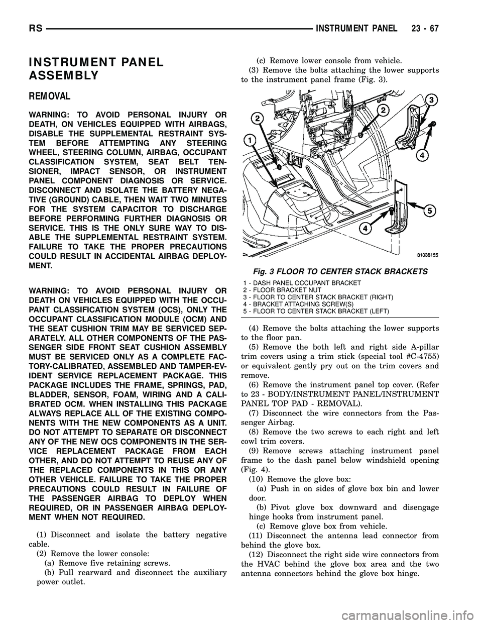
(3) Remove the bolts attaching the lower supports
to the instrument panel frame (Fig. 3).
(4) Remove the bolts attaching the lower supports
to the floor pan.
(5) Remove the both left and right side A-pillar
trim covers using a trim stick (special tool #C-4755)
or equivalent gently pry out on the trim covers and
remove.
(6) Remove the instrument panel top cover. (Refer
to 23 - BODY/INSTRUMENT PANEL/INSTRUMENT
PANEL TOP PAD - REMOVAL).
(7) Disconnect the wire connectors from the Pas-
senger Airbag.
(8) Remove the two screws to each right and left
cowl trim covers.
(9) Remove screws attaching instrument panel
frame to the dash panel below windshield opening
(Fig. 4).
(10) Remove the glove box:
(a) Push in on sides of glove box bin and lower
door.
(b) Pivot glove box downward and disengage
hinge hooks from instrument panel.
(c) Remove glove box from vehicle.
(11) Disconnect the antenna lead connector from
behind the glove box.
(12) Disconnect the right side wire connectors from
the HVAC behind the glove box area and the two
antenna connectors behind the glove box hinge.
Fig. 3 FLOOR TO CENTER STACK BRACKETS
1 - DASH PANEL OCCUPANT BRACKET
2 - FLOOR BRACKET NUT
3 - FLOOR TO CENTER STACK BRACKET (RIGHT)
4 - BRACKET ATTACHING SCREW(S)
5 - FLOOR TO CENTER STACK BRACKET (LEFT)
RSINSTRUMENT PANEL23-67
Page 1850 of 2339
(7) Place steering column cover plate into position
(Fig. 8).
(8) Install six instrument panel steering column
cover plate attaching screws.
(9) Install the screws attaching the instrument
panel reinforcement (Fig. 9).
(10) Place brake pedal support bracket into posi-
tion and install three nuts attaching to instrument
panel.
(11) Place steering column into position and install
four nuts retaining the steering column to the dash
panel steering column mounting bracket and lower
column to the floor (Fig. 7).
(12) Connect the Occupant Restraint Controller
(ORC) harness connector.
(13) Connect the steering column wiring. There
are seven connectors and clip the harness to the col-
umn.
(14) Connect the left side wiring:
(a) Brake switch.
(b) Main bulkhead connector.
(c) Five harness connectors.
(d) Driver airbag connector.
(15) Place steering column bearing shroud and
steering column shroud into position and install four
steering column shroud retaining screws (Fig. 6).
(16) Place fixed shroud into position and install
two steering column fixed shroud retaining screws
(Fig. 6).
(17) Install two screws to the hood release handle.
(18) Install the inflatable knee blocker. (Refer to
23 - BODY/INSTRUMENT PANEL/KNEE BLOCKER
- INSTALLATION).
(19) Install the lower steering column cover and
end cap. (Refer to 23 - BODY/INSTRUMENT PAN-
EL/LOWER STEERING COLUMN COVER AND
END CAP - INSTALLATION).
(20) Install the cluster bezel. (Refer to 23 - BODY/
INSTRUMENT PANEL/CLUSTER BEZEL -
INSTALLATION).
(21) Install over steering column cover. (Refer to
23 - BODY/INSTRUMENT PANEL/STEERING COL-
UMN OPENING COVER - INSTALLATION).
(22) Install the right end cover. Position over
retaining slots and firmly snap into place.
(23) Connect the right side wire connectors to the
HVAC behind the glove box area and the two
antenna connectors behind the glove box hinge.
(24) Install the glove box:
(a) Install glove box into the vehicle. Line up the
hinges and firmly snap together.(b) Push in on sides of glove box bin and raise
door.
(25) Install two screws to each right and left cowl
trim covers.
(26) Connect the wire connectors to the Passenger
Airbag.
(27) Install the screws attaching the instrument
panel frame to the dash panel below windshield
opening.
(28) Install screws attaching instrument panel
frame to the dash panel below windshield opening
(Fig. 4).
(29) Install the instrument panel top cover and
silencer. (Refer to 23 - BODY/INSTRUMENT PAN-
EL/INSTRUMENT PANEL TOP PAD - INSTALLA-
TION).
(30) Install both left and right side A-pillar trim
covers.
(31) Install bolts attaching the lower supports to
the floor pan (Fig. 3).
(32) Install bolts attaching the lower supports to
the instrument panel frame.
(33) Install the lower console:
(a) Install lower console to vehicle.
(b) Connect the auxiliary power outlet.
(c) Install the six retaining screws.
(34) Connect the battery negative cable.
INSTRUMENT PANEL CENTER
BEZEL
REMOVAL
(1) Disconnect and isolate the battery negative
cable.
(2) Insert the trim stick (special tool #C-4755) or
equivalent between access cover and center bezel
gently pry outward.
(3) Carefully pry the access cover from the instru-
ment panel (Fig. 10).
(4) Remove the two center bezel attaching screws.
(5) Using a trim stick or equivalent, gently pry out
on the edge of the instrument panel center bezel and
pull outward.
(6) Disconnect the wire connectors to the accessory
switches and HVAC control.
(7) Remove the instrument panel center bezel from
the vehicle.
RSINSTRUMENT PANEL23-71
INSTRUMENT PANEL ASSEMBLY (Continued)
Page 1852 of 2339
LOWER CONSOLE
REMOVAL
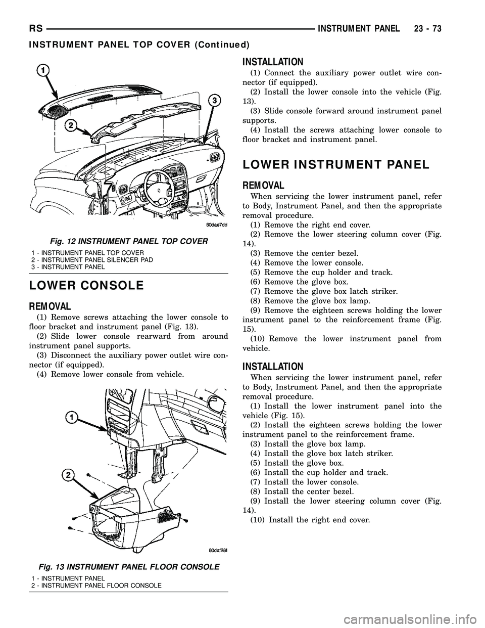
(1) Remove screws attaching the lower console to
floor bracket and instrument panel (Fig. 13).
(2) Slide lower console rearward from around
instrument panel supports.
(3) Disconnect the auxiliary power outlet wire con-
nector (if equipped).
(4) Remove lower console from vehicle.
INSTALLATION
(1) Connect the auxiliary power outlet wire con-
nector (if equipped).
(2) Install the lower console into the vehicle (Fig.
13).
(3) Slide console forward around instrument panel
supports.
(4) Install the screws attaching lower console to
floor bracket and instrument panel.
LOWER INSTRUMENT PANEL
REMOVAL
When servicing the lower instrument panel, refer
to Body, Instrument Panel, and then the appropriate
removal procedure.
(1) Remove the right end cover.
(2) Remove the lower steering column cover (Fig.
14).
(3) Remove the center bezel.
(4) Remove the lower console.
(5) Remove the cup holder and track.
(6) Remove the glove box.
(7) Remove the glove box latch striker.
(8) Remove the glove box lamp.
(9) Remove the eighteen screws holding the lower
instrument panel to the reinforcement frame (Fig.
15).
(10) Remove the lower instrument panel from
vehicle.
INSTALLATION
When servicing the lower instrument panel, refer
to Body, Instrument Panel, and then the appropriate
removal procedure.
(1) Install the lower instrument panel into the
vehicle (Fig. 15).
(2) Install the eighteen screws holding the lower
instrument panel to the reinforcement frame.
(3) Install the glove box lamp.
(4) Install the glove box latch striker.
(5) Install the glove box.
(6) Install the cup holder and track.
(7) Install the lower console.
(8) Install the center bezel.
(9) Install the lower steering column cover (Fig.
14).
(10) Install the right end cover.
Fig. 12 INSTRUMENT PANEL TOP COVER
1 - INSTRUMENT PANEL TOP COVER
2 - INSTRUMENT PANEL SILENCER PAD
3 - INSTRUMENT PANEL
Fig. 13 INSTRUMENT PANEL FLOOR CONSOLE
1 - INSTRUMENT PANEL
2 - INSTRUMENT PANEL FLOOR CONSOLE
RSINSTRUMENT PANEL23-73
INSTRUMENT PANEL TOP COVER (Continued)
Page 1856 of 2339
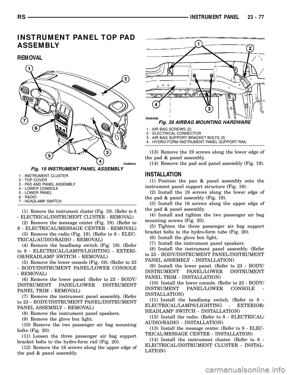
INSTRUMENT PANEL TOP PAD
ASSEMBLY
REMOVAL
(1)Remove the instrument cluster (Fig. 19). (Refer to 8
- ELECTRICAL/INSTRUMENT CLUSTER - REMOVAL)
(2) Remove the message center (Fig. 19). (Refer to
8 - ELECTRICAL/MESSAGE CENTER - REMOVAL)
(3) Remove the radio (Fig. 19). (Refer to 8 - ELEC-
TRICAL/AUDIO/RADIO - REMOVAL)
(4) Remove the headlamp switch (Fig. 19). (Refer
to 8 - ELECTRICAL/LAMPS/LIGHTING - EXTERI-
OR/HEADLAMP SWITCH - REMOVAL)
(5) Remove the lower console (Fig. 19). (Refer to 23
- BODY/INSTRUMENT PANEL/LOWER CONSOLE
- REMOVAL)
(6) Remove the lower panel. (Refer to 23 - BODY/
INSTRUMENT PANEL/LOWER INSTRUMENT
PANEL TRIM - REMOVAL)
(7) Remove the instrument panel assembly. (Refer
to 23 - BODY/INSTRUMENT PANEL/INSTRUMENT
PANEL ASSEMBLY - REMOVAL)
(8) Remove the instrument panel speakers.
(9) Remove the glove box light.
(10) Remove the two passenger air bag mounting
bolts (Fig. 20).
(11) Loosen the three passenger air bag support
bracket bolts to the hydro-form rail (Fig. 20).
(12) Remove the 16 screws along the upper edge of
the pad & panel assembly.(13) Remove the 19 screws along the lower edge of
the pad & panel assembly.
(14) Remove the pad and panel assembly (Fig. 19).
INSTALLATION
(1) Position the pan & panel assembly onto the
instrument panel support structure (Fig. 19).
(2) Install the 19 screws along the lower edge of
the pad & panel assembly (Fig. 19).
(3) Install the 16 screws along the upper edge of
the pad & panel assembly.
(4) Install and tighten the two passenger air bag
mounting screws (Fig. 20).
(5) Tighten the three passenger air bag support
bracket bolts to the hydro-form tube (Fig. 20).
(6) Install the glove box light.
(7) Install the instrument panel speakers.
(8) Install the instrument panel assembly. (Refer
to 23 - BODY/INSTRUMENT PANEL/INSTRUMENT
PANEL ASSEMBLY - INSTALLATION)
(9) Install the lower panel. (Refer to 23 - BODY/
INSTRUMENT PANEL/LOWER INSTRUMENT
PANEL TRIM - INSTALLATION)
(10) Install the lower console. (Refer to 23 - BODY/
INSTRUMENT PANEL/LOWER CONSOLE -
INSTALLATION)
(11) Install the headlamp switch. (Refer to 8 -
ELECTRICAL/LAMPS/LIGHTING - EXTERIOR/
HEADLAMP SWITCH - INSTALLATION)
(12) Install the radio. (Refer to 8 - ELECTRICAL/
AUDIO/RADIO - INSTALLATION)
(13)
Install the message center. (Refer to 8 - ELEC-
TRICAL/MESSAGE CENTER - INSTALLATION)
(14) Install the instrument cluster. (Refer to 8 -
ELECTRICAL/INSTRUMENT CLUSTER - INSTAL-
LATION)
Fig. 19 INSTRUMENT PANEL ASSEMBLY
1 - INSTRUMENT CLUSTER
2 - TOP COVER
3 - PAD AND PANEL ASSEMBLY
4 - LOWER CONSOLE
5 - LOWER PANEL
6 - RADIO
7 - HEADLAMP SWITCH
Fig. 20 AIRBAG MOUNTING HARDWARE
1 - AIR BAG SCREWS (2)
2 - ELECTRICAL CONNECTOR
3 - AIR BAG SUPPORT BRACKET BOLTS (3)
4 - HYDRO-FORM INSTRUMENT PANEL SUPPORT RAIL
RSINSTRUMENT PANEL23-77
Page 1860 of 2339
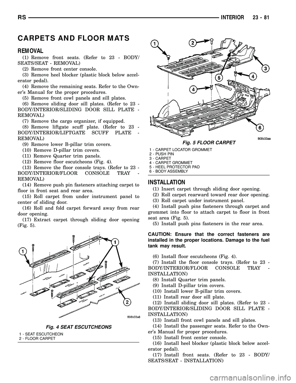
CARPETS AND FLOOR MATS
REMOVAL
(1) Remove front seats. (Refer to 23 - BODY/
SEATS/SEAT - REMOVAL)
(2) Remove front center console.
(3) Remove heel blocker (plastic block below accel-
erator pedal).
(4) Remove the remaining seats. Refer to the Own-
er's Manual for the proper procedures.
(5) Remove front cowl panels and sill plates.
(6) Remove sliding door sill plates. (Refer to 23 -
BODY/INTERIOR/SLIDING DOOR SILL PLATE -
REMOVAL)
(7) Remove the cargo organizer, if equipped.
(8) Remove liftgate scuff plate. (Refer to 23 -
BODY/INTERIOR/LIFTGATE SCUFF PLATE -
REMOVAL)
(9) Remove lower B-pillar trim covers.
(10) Remove D-pillar trim covers.
(11) Remove Quarter trim panels.
(12) Remove floor escutcheons (Fig. 4).
(13) Remove the floor console trays. (Refer to 23 -
BODY/INTERIOR/FLOOR CONSOLE TRAY -
REMOVAL)
(14) Remove push pin fasteners attaching carpet to
floor in front seat and rear area.
(15) Roll carpet from under instrument panel to
center of sliding door.
(16) Roll and fold carpet forward away from rear
door opening.
(17) Extract carpet through sliding door opening
(Fig. 5).
INSTALLATION
(1) Insert carpet through sliding door opening.
(2) Roll carpet rearward toward rear door opening.
(3) Roll carpet under instrument panel.
(4) Install push pins fasteners through carpet and
grommet into floor to attach carpet to floor in front
seat area (Fig. 5).
(5) Install push pins fasteners in the rear area.
CAUTION: Ensure that the correct fasteners are
installed in the proper locations. Damage to the fuel
tank may result.
(6) Install floor escutcheons (Fig. 4).
(7) Install the floor console trays. (Refer to 23 -
BODY/INTERIOR/FLOOR CONSOLE TRAY -
INSTALLATION)
(8) Install Quarter trim panels.
(9) Install D-pillar trim covers.
(10) Install lower B-pillar trim covers.
(11) Install rear door sill plate.
(12) Install sliding door sill plates. (Refer to 23 -
BODY/INTERIOR/SLIDING DOOR SILL PLATE -
INSTALLATION)
(13) Install front cowl panels and sill plates.
(14) Install the passenger seats. Refer to the Own-
er's Manual for proper procedures.
(15) Install front center console.
(16) Install heel blocker (plastic block below accel-
erator pedal).
(17) Install front seats. (Refer to 23 - BODY/
SEATS/SEAT - INSTALLATION)
Fig. 4 SEAT ESCUTCHEONS
1 - SEAT ESCUTCHEON
2 - FLOOR CARPET
Fig. 5 FLOOR CARPET
1 - CARPET LOCATOR GROMMET
2 - PUSH PIN
3 - CARPET
4 - CARPET GROMMET
5 - HEEL PROTECTOR PAD
6 - BODY ASSEMBLY
RSINTERIOR23-81
Page 1870 of 2339
HEADLINER
REMOVAL
(1) Remove sun visors and vanity mirrors.
(2) Remove sun visor center supports.
(3) If equipped, remove coat hooks.
(4) If equipped, remove roof rail modules.
(5) Remove A-pillar trim covers. (Refer to 23 -
BODY/INTERIOR/A-PILLAR TRIM - REMOVAL).
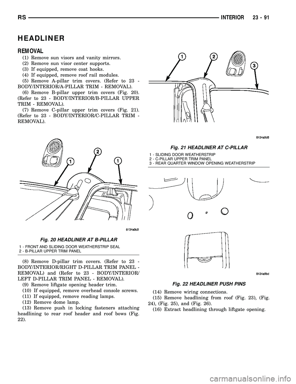
(6) Remove B-pillar upper trim covers (Fig. 20).
(Refer to 23 - BODY/INTERIOR/B-PILLAR UPPER
TRIM - REMOVAL).
(7) Remove C-pillar upper trim covers (Fig. 21).
(Refer to 23 - BODY/INTERIOR/C-PILLAR TRIM -
REMOVAL).
(8) Remove D-pillar trim covers. (Refer to 23 -
BODY/INTERIOR/RIGHT D-PILLAR TRIM PANEL -
REMOVAL) and (Refer to 23 - BODY/INTERIOR/
LEFT D-PILLAR TRIM PANEL - REMOVAL).
(9) Remove liftgate opening header trim.
(10) If equipped, remove overhead console screws.
(11) If equipped, remove reading lamps.
(12) Remove dome lamp.
(13) Remove push in locking fasteners attaching
headlining to rear roof header and roof bows (Fig.
22).(14) Remove wiring connections.
(15) Remove headlining from roof (Fig. 23), (Fig.
24), (Fig. 25), and (Fig. 26).
(16) Extract headlining through liftgate opening.
Fig. 20 HEADLINER AT B-PILLAR
1 - FRONT AND SLIDING DOOR WEATHERSTRIP SEAL
2 - B-PILLAR UPPER TRIM PANEL
Fig. 21 HEADLINER AT C-PILLAR
1 - SLIDING DOOR WEATHERSTRIP
2 - C-PILLAR UPPER TRIM PANEL
3 - REAR QUARTER WINDOW OPENING WEATHERSTRIP
Fig. 22 HEADLINER PUSH PINS
RSINTERIOR23-91
Page 1872 of 2339
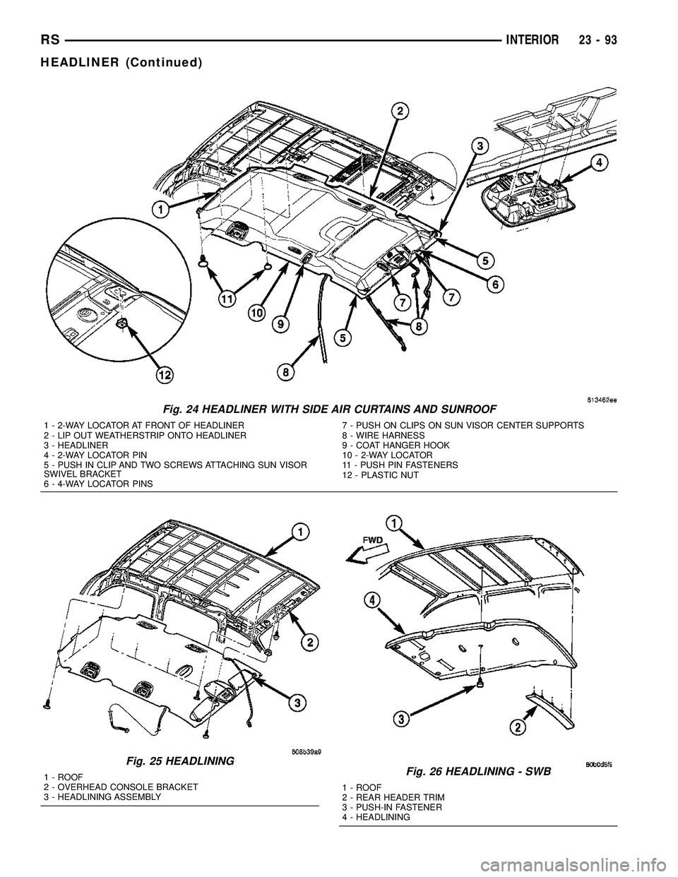
Fig. 24 HEADLINER WITH SIDE AIR CURTAINS AND SUNROOF
1 - 2-WAY LOCATOR AT FRONT OF HEADLINER
2 - LIP OUT WEATHERSTRIP ONTO HEADLINER
3 - HEADLINER
4 - 2-WAY LOCATOR PIN
5 - PUSH IN CLIP AND TWO SCREWS ATTACHING SUN VISOR
SWIVEL BRACKET
6 - 4-WAY LOCATOR PINS7 - PUSH ON CLIPS ON SUN VISOR CENTER SUPPORTS
8 - WIRE HARNESS
9 - COAT HANGER HOOK
10 - 2-WAY LOCATOR
11 - PUSH PIN FASTENERS
12 - PLASTIC NUT
Fig. 25 HEADLINING
1 - ROOF
2 - OVERHEAD CONSOLE BRACKET
3 - HEADLINING ASSEMBLYFig. 26 HEADLINING - SWB
1 - ROOF
2 - REAR HEADER TRIM
3 - PUSH-IN FASTENER
4 - HEADLINING
RSINTERIOR23-93
HEADLINER (Continued)