ESP inoperative CHRYSLER CARAVAN 2005 Service Manual
[x] Cancel search | Manufacturer: CHRYSLER, Model Year: 2005, Model line: CARAVAN, Model: CHRYSLER CARAVAN 2005Pages: 2339, PDF Size: 59.69 MB
Page 376 of 2339
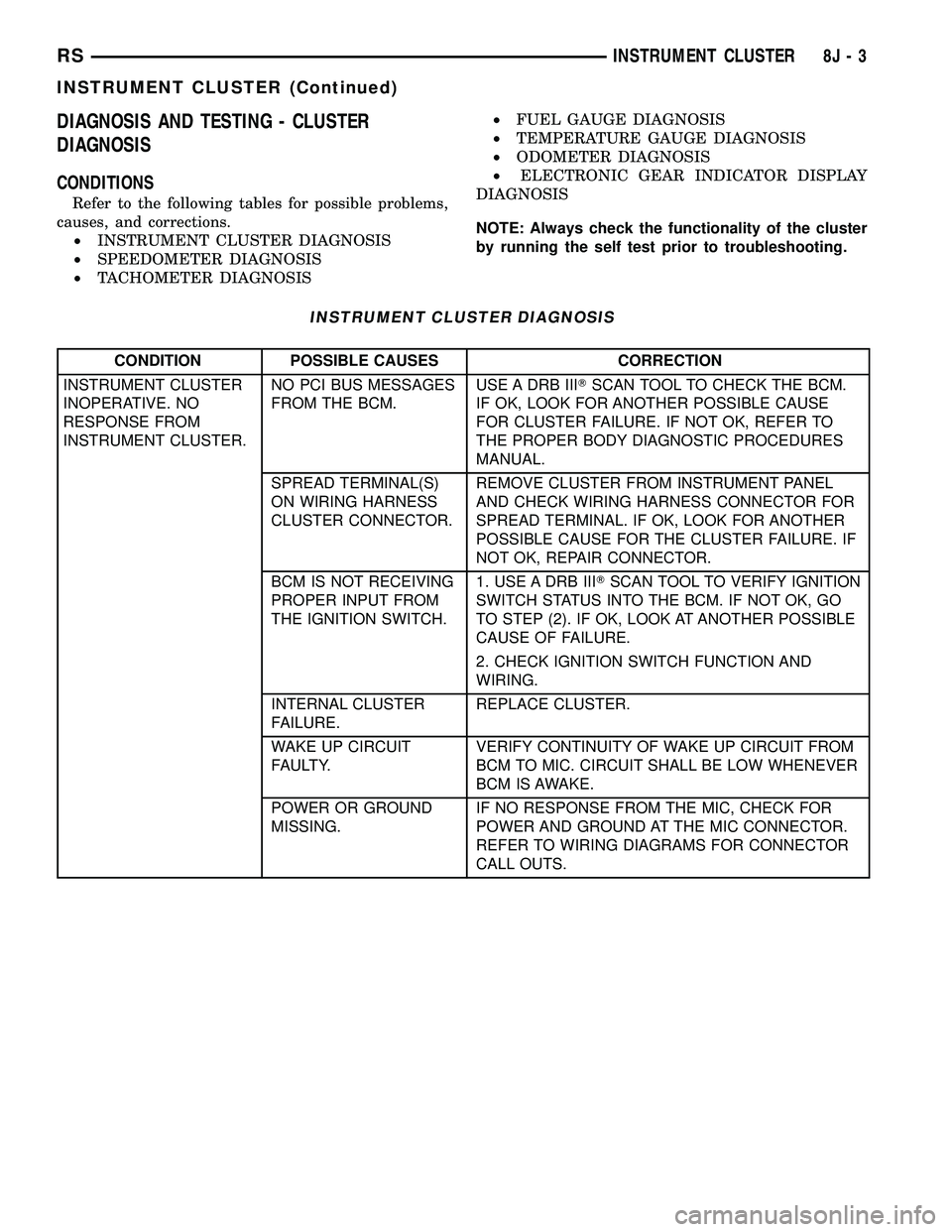
DIAGNOSIS AND TESTING - CLUSTER
DIAGNOSIS
CONDITIONS
Refer to the following tables for possible problems,
causes, and corrections.
²INSTRUMENT CLUSTER DIAGNOSIS
²SPEEDOMETER DIAGNOSIS
²TACHOMETER DIAGNOSIS²FUEL GAUGE DIAGNOSIS
²TEMPERATURE GAUGE DIAGNOSIS
²ODOMETER DIAGNOSIS
²ELECTRONIC GEAR INDICATOR DISPLAY
DIAGNOSIS
NOTE: Always check the functionality of the cluster
by running the self test prior to troubleshooting.
INSTRUMENT CLUSTER DIAGNOSIS
CONDITION POSSIBLE CAUSES CORRECTION
INSTRUMENT CLUSTER
INOPERATIVE. NO
RESPONSE FROM
INSTRUMENT CLUSTER.NO PCI BUS MESSAGES
FROM THE BCM.USE A DRB IIITSCAN TOOL TO CHECK THE BCM.
IF OK, LOOK FOR ANOTHER POSSIBLE CAUSE
FOR CLUSTER FAILURE. IF NOT OK, REFER TO
THE PROPER BODY DIAGNOSTIC PROCEDURES
MANUAL.
SPREAD TERMINAL(S)
ON WIRING HARNESS
CLUSTER CONNECTOR.REMOVE CLUSTER FROM INSTRUMENT PANEL
AND CHECK WIRING HARNESS CONNECTOR FOR
SPREAD TERMINAL. IF OK, LOOK FOR ANOTHER
POSSIBLE CAUSE FOR THE CLUSTER FAILURE. IF
NOT OK, REPAIR CONNECTOR.
BCM IS NOT RECEIVING
PROPER INPUT FROM
THE IGNITION SWITCH.1. USE A DRB IIITSCAN TOOL TO VERIFY IGNITION
SWITCH STATUS INTO THE BCM. IF NOT OK, GO
TO STEP (2). IF OK, LOOK AT ANOTHER POSSIBLE
CAUSE OF FAILURE.
2. CHECK IGNITION SWITCH FUNCTION AND
WIRING.
INTERNAL CLUSTER
FAILURE.REPLACE CLUSTER.
WAKE UP CIRCUIT
FAULTY.VERIFY CONTINUITY OF WAKE UP CIRCUIT FROM
BCM TO MIC. CIRCUIT SHALL BE LOW WHENEVER
BCM IS AWAKE.
POWER OR GROUND
MISSING.IF NO RESPONSE FROM THE MIC, CHECK FOR
POWER AND GROUND AT THE MIC CONNECTOR.
REFER TO WIRING DIAGRAMS FOR CONNECTOR
CALL OUTS.
RSINSTRUMENT CLUSTER8J-3
INSTRUMENT CLUSTER (Continued)
Page 420 of 2339
NOTE: If a new CMTC module has been installed,
the compass will have to be calibrated and the vari-
ance set. (Refer to 8 - ELECTRICAL/OVERHEAD
CONSOLE - STANDARD PROCEDURE - COMPASS
CALIBRATION).
UNIVERSAL TRANSMITTER
DESCRIPTION
A Universal Transmitter transceiver is available on
some vehicles. The universal transmitter transceiver
is integral to the Electronic Vehicle Information Cen-
ter (EVIC) and the Compass Mini-Trip Computer
(CMTC) modules, which are located in the overhead
console. The only visible component of the universal
transmitter are the three transmitter push buttons
centered between the modules push buttons located
just rearward of the display screen in the overhead
console. The three universal transmitter push but-
tons are identified with one, two or three light indi-
cators so that they can be easily identified.
Each of the three universal transmitter push but-
tons controls an independent radio transmitter chan-
nel. Each of these three channels can be trained to
transmit a different radio frequency signal for the
remote operation of garage door openers, motorized
gate openers, home or office lighting, security sys-
tems or just about any other device that can be
equipped with a radio receiver in the 286 to 399
MegaHertz (MHz) frequency range for remote opera-
tion. The universal transmitter is capable of operat-
ing systems using either rolling code or non-rolling
code technology.
The electronics module displays messages and a
small house-shaped icon with one, two or three dots
corresponding to the three transmitter buttons to
indicate the status of the universal transmitter. The
EVIC messages are:
²Cleared Channels- Indicates that all of the
transmitter codes stored in the universal transmitter
have been successfully cleared.
²Training- Indicates that the universal trans-
mitter is in its transmitter learning mode.
²Trained- Indicates that the universal transmit-
ter has successfully acquired a new transmitter code.
²Transmit- Indicates that a trained universal
transmitter button has been depressed and that the
universal transmitter is transmitting.
The universal transmitter cannot be repaired, and
is available for service only as a unit with the EVIC
or CMTC modules. If any of these components is
faulty or damaged, the complete EVIC or CMTC
module must be replaced.
DIAGNOSIS AND TESTING
UNIVERSAL TRANSMITTER
If both the Universal Transmitter and the Elec-
tronic Vehicle Information Center (EVIC) are inoper-
ative, (Refer to 8 - ELECTRICAL/OVERHEAD
CONSOLE/ELECTRONIC VEHICLE INFO CENTER
- DIAGNOSIS AND TESTING). If the Universal
Transmitter is inoperative, but the EVIC is operating
normally, retrain the Transmitter with a known good
transmitter (Refer to 8 - ELECTRICAL/OVERHEAD
CONSOLE/UNIVERSAL TRANSMITTER - STAN-
DARD PROCEDURE - SETTING TRANSMITTER
CODES). If the unit is still inoperative, test the uni-
versal transmitter with the Radio Frequency Detec-
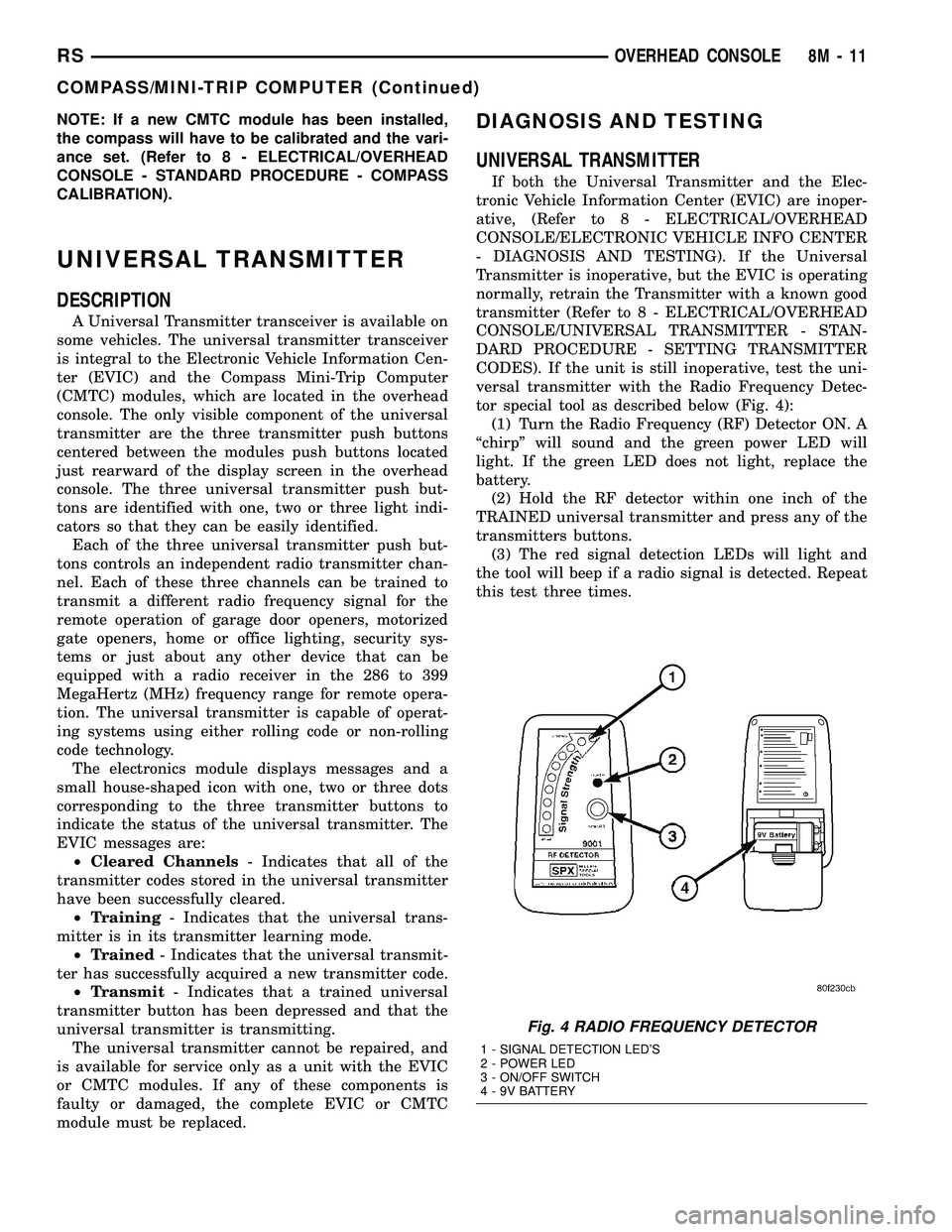
tor special tool as described below (Fig. 4):
(1) Turn the Radio Frequency (RF) Detector ON. A
ªchirpº will sound and the green power LED will
light. If the green LED does not light, replace the
battery.
(2) Hold the RF detector within one inch of the
TRAINED universal transmitter and press any of the
transmitters buttons.
(3) The red signal detection LEDs will light and
the tool will beep if a radio signal is detected. Repeat
this test three times.
Fig. 4 RADIO FREQUENCY DETECTOR
1 - SIGNAL DETECTION LED'S
2 - POWER LED
3 - ON/OFF SWITCH
4 - 9V BATTERY
RSOVERHEAD CONSOLE8M-11
COMPASS/MINI-TRIP COMPUTER (Continued)
Page 421 of 2339
STANDARD PROCEDURE
SETTING TRANSMITTER CODES
(1) Turn off the engine.
(2) Erase the codes by pressing the two outside
buttons. Release the buttons when the display con-
firms the operation (about 20 seconds).
(3) Choose one of the three buttons to train. Place
the hand-held transmitter within one inch of the uni-
versal transmitter and push the buttons on both
transmitters.
(4) Release both buttons. Your universal transmit-
ter is now ªtrainedº. To train the other buttons,
repeat Step 3 and Step 4. Be sure to keep your hand-
held transmitter in case you need to retrain the uni-
versal transmitter.
ERASING TRANSMITTER CODES
To erase the universal transmitter codes, simply
hold down the two outside buttons until the display
confirms the operation.
NOTE: Individual channels cannot be erased. Eras-
ing the transmitter codes will erase ALL pro-
grammed codes.
REMOVAL
(1) For the universal transmitter removal proce-
dure, (Refer to 8 - ELECTRICAL/OVERHEAD CON-
SOLE/COMPASS/MINI-TRIP COMPUTER -
REMOVAL.
AMBIENT TEMP SENSOR
DESCRIPTION
Ambient air temperature is monitored by the over-
head console through ambient temperature messages
received from the Powertrain Control Module (PCM)
over the Programmable Communications Interface
(PCI) data bus circuit. The PCM receives a hard
wired input from the ambient temperature sensor.
The ambient temperature sensor is a variable resis-
tor mounted to a bracket that is secured with a screw
to the right side of the headlamp mounting module
grille opening, behind the radiator grille and in front
of the engine compartment.
For additional information on the PCM, (Refer to 8
- ELECTRICAL/ELECTRONIC CONTROL MOD-
ULES/POWERTRAIN CONTROL MODULE -
DESCRIPTION).
OPERATION
The ambient temperature sensor is a variable
resistor that operates on a five-volt reference signal
sent by the Powertrain Control Module (PCM). The
resistance in the sensor changes as temperature
changes, changing the temperature sensor signal cir-
cuit voltage to the PCM. Based upon the resistance
in the sensor, the PCM senses a specific voltage on
the temperature sensor signal circuit, which it is pro-
grammed to correspond to a specific temperature.
The PCM then sends the proper ambient tempera-
ture messages to the Electronic Vehicle Information
Center (EVIC)/Compass Mini-Trip Computer (CMTC)
over the Programmable Communication Interface
(PCI) data bus.
The thermometer function is supported by the
ambient temperature sensor, a wiring circuit, the
PCM, the PCI data bus, and the Electronics module.
If any portion of the ambient temperature sensor cir-
cuit fails, the PCM will self-diagnose the circuit.
The ambient temperature sensor circuit can also be
diagnosed manually (Refer to 8 - ELECTRICAL/
OVERHEAD CONSOLE/AMBIENT TEMP SENSOR
- DIAGNOSIS AND TESTING - AMBIENT TEM-
PERATURE SENSOR CIRCUIT). If the temperature
sensor and circuit are confirmed to be OK, but the
temperature display is inoperative or incorrect,
(Refer to 8 - ELECTRICAL/OVERHEAD CONSOLE -
DIAGNOSIS AND TESTING) to determine the cause.
For complete circuit diagrams, refer to the appropri-
ate wiring information.
DIAGNOSIS AND TESTING
AMBIENT TEMPERATURE SENSOR
(1) Turn the ignition switch to the Off position.
Disconnect and isolate the battery negative cable.
Disconnect the ambient temperature sensor wire har-
ness connector.
(2) Measure the resistance of the ambient temper-
ature sensor. At room temperature (approx. 68ÉF),
the sensor resistance should be between 10-13 Kilo-
hms. The sensor resistance should be between these
two values at 68ÉF. If the resistance is out of range
replace the ambient temperature sensor.
AMBIENT TEMPERATURE SENSOR CIRCUIT
(1) Turn the ignition switch to the Off position.
Disconnect and isolate the battery negative cable.
Disconnect the ambient temperature sensor wire har-
ness connector and the Powertrain Control Module
(PCM) wire harness connector.
8M - 12 OVERHEAD CONSOLERS
UNIVERSAL TRANSMITTER (Continued)
Page 475 of 2339
NOTE: Push in on the push-pins at the clutch hous-
ing (plastic side) until you hear one click. Push in
on the push-pin fasteners at the motor mount
(sheet metal side) until you hear two clicks. This
assures proper installation/attachment of the motor
to the sliding door.
(3) Install the flex shaft by lining up the square
shaped drive shaft with the corresponding hole in the
door motor drive unit and push straight in.
(4) Install the E-clip to secure flex-shaft.
(5) Install the weather shield as necessary.
(6) Install the door trim panel on the sliding door,
(Refer to 23 - BODY/DOORS - SLIDING/TRIM
PANEL - INSTALLATION) for the procedure.
(7) Connect the battery negative cable.
FULL OPEN SWITCH
DESCRIPTION
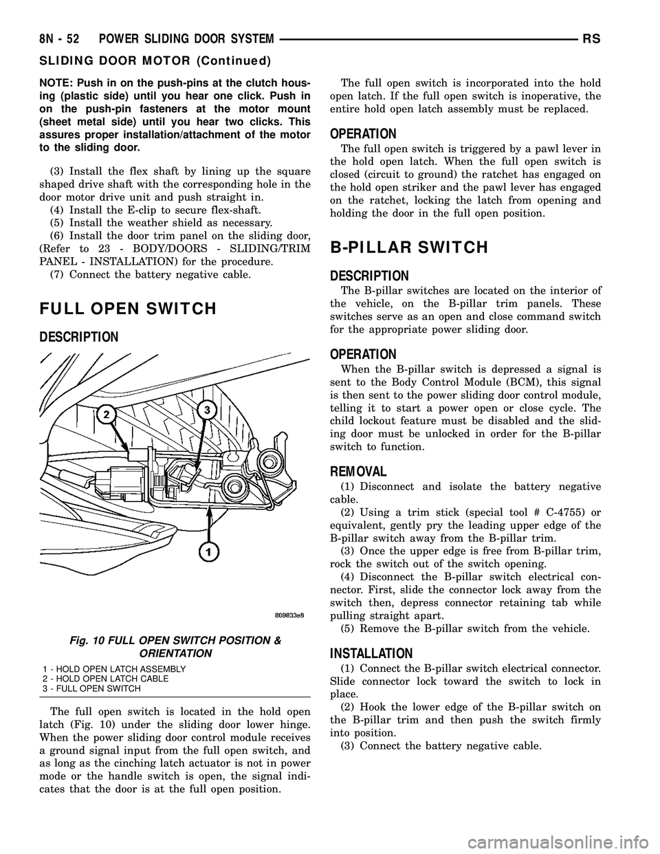
The full open switch is located in the hold open
latch (Fig. 10) under the sliding door lower hinge.
When the power sliding door control module receives
a ground signal input from the full open switch, and
as long as the cinching latch actuator is not in power
mode or the handle switch is open, the signal indi-
cates that the door is at the full open position.The full open switch is incorporated into the hold
open latch. If the full open switch is inoperative, the
entire hold open latch assembly must be replaced.
OPERATION
The full open switch is triggered by a pawl lever in
the hold open latch. When the full open switch is
closed (circuit to ground) the ratchet has engaged on
the hold open striker and the pawl lever has engaged
on the ratchet, locking the latch from opening and
holding the door in the full open position.
B-PILLAR SWITCH
DESCRIPTION
The B-pillar switches are located on the interior of
the vehicle, on the B-pillar trim panels. These
switches serve as an open and close command switch
for the appropriate power sliding door.
OPERATION
When the B-pillar switch is depressed a signal is
sent to the Body Control Module (BCM), this signal
is then sent to the power sliding door control module,
telling it to start a power open or close cycle. The
child lockout feature must be disabled and the slid-
ing door must be unlocked in order for the B-pillar
switch to function.
REMOVAL
(1) Disconnect and isolate the battery negative
cable.
(2) Using a trim stick (special tool # C-4755) or
equivalent, gently pry the leading upper edge of the
B-pillar switch away from the B-pillar trim.
(3) Once the upper edge is free from B-pillar trim,
rock the switch out of the switch opening.
(4) Disconnect the B-pillar switch electrical con-
nector. First, slide the connector lock away from the
switch then, depress connector retaining tab while
pulling straight apart.
(5) Remove the B-pillar switch from the vehicle.
INSTALLATION
(1) Connect the B-pillar switch electrical connector.
Slide connector lock toward the switch to lock in
place.
(2) Hook the lower edge of the B-pillar switch on
the B-pillar trim and then push the switch firmly
into position.
(3) Connect the battery negative cable.
Fig. 10 FULL OPEN SWITCH POSITION &
ORIENTATION
1 - HOLD OPEN LATCH ASSEMBLY
2 - HOLD OPEN LATCH CABLE
3 - FULL OPEN SWITCH
8N - 52 POWER SLIDING DOOR SYSTEMRS
SLIDING DOOR MOTOR (Continued)
Page 534 of 2339
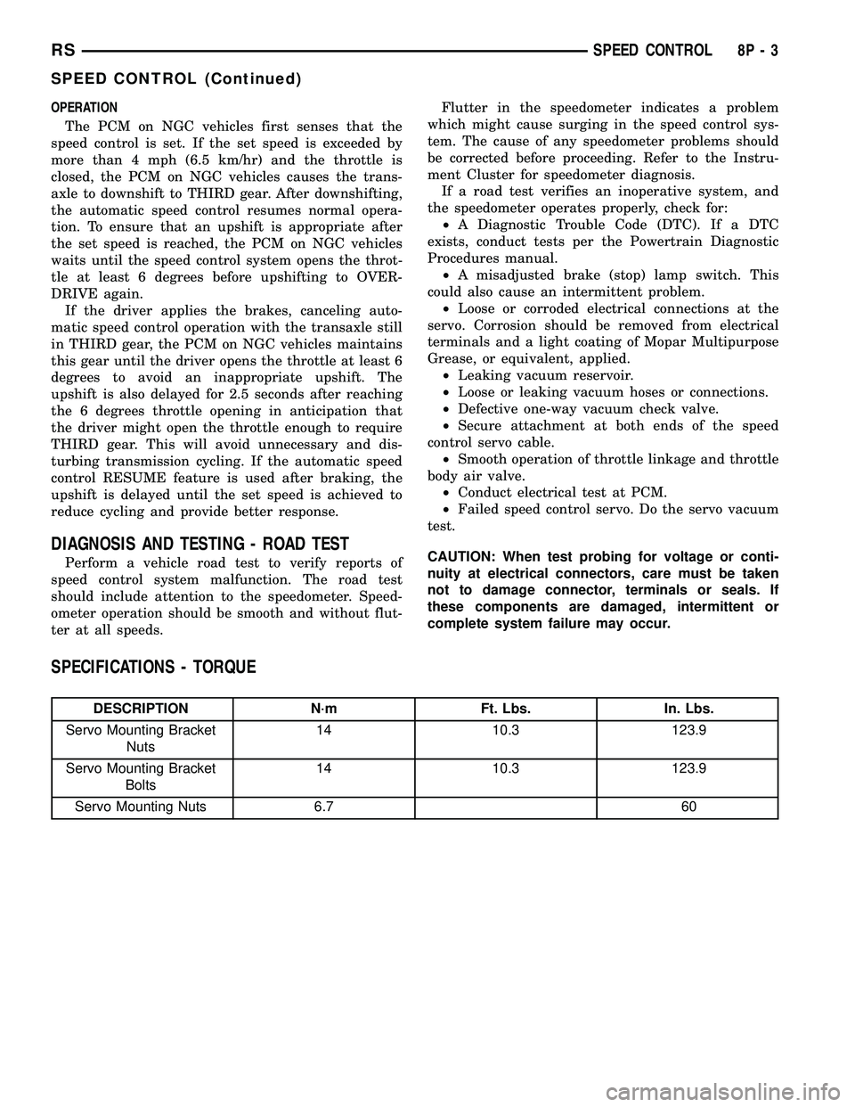
OPERATION
The PCM on NGC vehicles first senses that the
speed control is set. If the set speed is exceeded by
more than 4 mph (6.5 km/hr) and the throttle is
closed, the PCM on NGC vehicles causes the trans-
axle to downshift to THIRD gear. After downshifting,
the automatic speed control resumes normal opera-
tion. To ensure that an upshift is appropriate after
the set speed is reached, the PCM on NGC vehicles
waits until the speed control system opens the throt-
tle at least 6 degrees before upshifting to OVER-
DRIVE again.
If the driver applies the brakes, canceling auto-
matic speed control operation with the transaxle still
in THIRD gear, the PCM on NGC vehicles maintains
this gear until the driver opens the throttle at least 6
degrees to avoid an inappropriate upshift. The
upshift is also delayed for 2.5 seconds after reaching
the 6 degrees throttle opening in anticipation that
the driver might open the throttle enough to require
THIRD gear. This will avoid unnecessary and dis-
turbing transmission cycling. If the automatic speed
control RESUME feature is used after braking, the
upshift is delayed until the set speed is achieved to
reduce cycling and provide better response.
DIAGNOSIS AND TESTING - ROAD TEST
Perform a vehicle road test to verify reports of
speed control system malfunction. The road test
should include attention to the speedometer. Speed-
ometer operation should be smooth and without flut-
ter at all speeds.Flutter in the speedometer indicates a problem
which might cause surging in the speed control sys-
tem. The cause of any speedometer problems should
be corrected before proceeding. Refer to the Instru-
ment Cluster for speedometer diagnosis.
If a road test verifies an inoperative system, and
the speedometer operates properly, check for:
²A Diagnostic Trouble Code (DTC). If a DTC
exists, conduct tests per the Powertrain Diagnostic
Procedures manual.
²A misadjusted brake (stop) lamp switch. This
could also cause an intermittent problem.
²Loose or corroded electrical connections at the
servo. Corrosion should be removed from electrical
terminals and a light coating of Mopar Multipurpose
Grease, or equivalent, applied.
²Leaking vacuum reservoir.
²Loose or leaking vacuum hoses or connections.
²Defective one-way vacuum check valve.
²Secure attachment at both ends of the speed
control servo cable.
²Smooth operation of throttle linkage and throttle
body air valve.
²Conduct electrical test at PCM.
²Failed speed control servo. Do the servo vacuum
test.
CAUTION: When test probing for voltage or conti-
nuity at electrical connectors, care must be taken
not to damage connector, terminals or seals. If
these components are damaged, intermittent or
complete system failure may occur.
SPECIFICATIONS - TORQUE
DESCRIPTION N´m Ft. Lbs. In. Lbs.
Servo Mounting Bracket
Nuts14 10.3 123.9
Servo Mounting Bracket
Bolts14 10.3 123.9
Servo Mounting Nuts 6.7 60
RSSPEED CONTROL8P-3
SPEED CONTROL (Continued)
Page 542 of 2339
When the ignition switch is moved to the RUN
position, the SKREEM transmits an Radio Frequency
(RF) signal to the transponder in the ignition key.
The SKREEM then waits for a response RF signal
from the transponder in the key. If the response
received identifies the key as valid, the SKREEM
sends a9valid key9message to the Powertrain Con-
trol Module (PCM) over the Programmable Commu-
nication Interface (PCI) data bus. If the response
received identifies the key as invalid or no response
is received from the transponder in the ignition key,
the SKREEM sends an9invalid key9message to the
PCM. The PCM will enable or disable engine opera-
tion based upon the status of the SKREEM mes-
sages. It is important to note that the default
condition in the PCM is9invalid key.9Therefore, if no
response is received by the PCM, the engine will be
immobilized after two (2) seconds of running.
The SKREEM also sends indicator light status
messages to the Mechanical Instrument Cluster
(MIC) to operate the light. This is the method used to
turn the light ON solid or to flash it after the indi-
cator light test is complete to signify a fault in the
SKREES. If the light comes ON and stays ON solid
after the indicator light test, this signifies that the
SKREEM has detected a system malfunction and/or
that the SKREES has become inoperative. If the
SKREEM detects an invalid keyORa key-related
fault exists, the indicator light will flash following
the indicator light test. The SKREEM may also
request an audible chime if the customer key pro-
gramming feature is available and the procedure is
being utilized (Refer to 8 - ELECTRICAL/VEHICLE
THEFT SECURITY/TRANSPONDER KEY - STAN-
DARD PROCEDURE).
REMOTE KEYLESS ENTRY (RKE)
After pressing the lock button on the RKE trans-
mitter, all of the door locks will lock, the illuminated
entry will turn off (providing all doors are closed),
and the VTSS (if equipped) will arm. After pressing
the unlock button, on the RKE transmitter, one time,
the driver door lock will unlock, the illuminated
entry will turn on the courtesy lamps, and the VTSS
(if equipped) will disarm. After pressing the unlock
button a second time, the remaining door locks will
unlock. The Electronic Vehicle Information Center
(EVIC) or the DRBIIItscan tool can reprogram this
feature to unlock all of the door locks with one press
of the unlock button. If the vehicle is equipped with
the memory system, the memory message will iden-
tify which transmitter (1 or 2) sent the signal.The SKREEM is capable of retaining up to 8 indi-
vidual access codes (8 transmitters). If the PRNDL is
in any position except park, the SKREEM will dis-
able the RKE. The 4 button transmitter uses
1-CR2032 battery. The minimum battery life is
approximately 4.7 years based on 20 transmissions a
day at 84ÉF (25ÉC). Use the DRBIIItscan tool or the
Miller Tool 9001 RF Detector to test the RKE trans-
mitter. Use the DRBIIItor the customer program-
ming method to program the RKE system. However,
the SKREEM will only allow RKE programming
when the ignition is in the ON position, the PRNDL
is in park position, and the VTSS (if equipped) is dis-
armed.
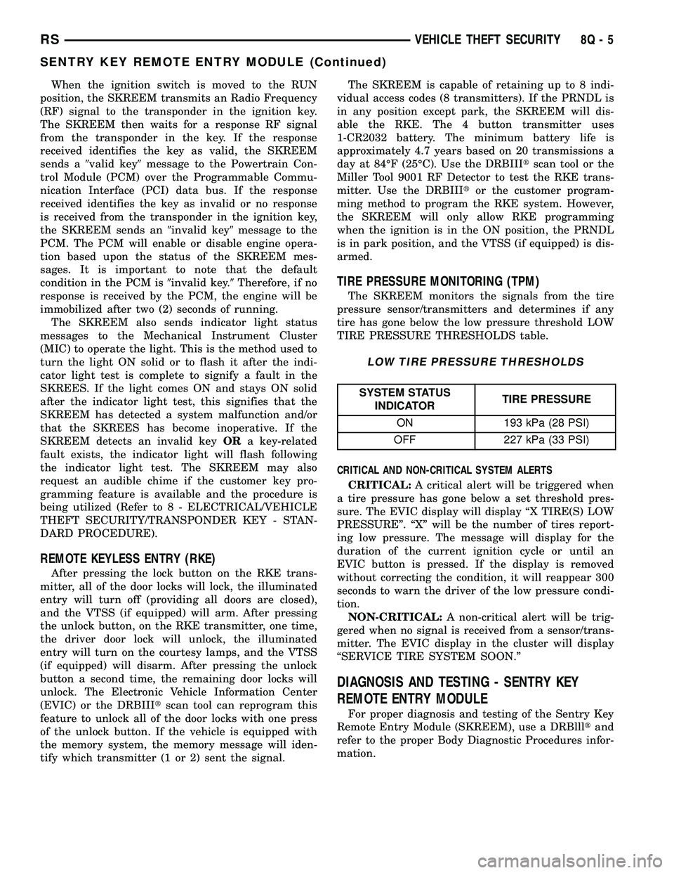
TIRE PRESSURE MONITORING (TPM)
The SKREEM monitors the signals from the tire
pressure sensor/transmitters and determines if any
tire has gone below the low pressure threshold LOW
TIRE PRESSURE THRESHOLDS table.
LOW TIRE PRESSURE THRESHOLDS
SYSTEM STATUS
INDICATORTIRE PRESSURE
ON 193 kPa (28 PSI)
OFF 227 kPa (33 PSI)
CRITICAL AND NON-CRITICAL SYSTEM ALERTS
CRITICAL:A critical alert will be triggered when
a tire pressure has gone below a set threshold pres-
sure. The EVIC display will display ªX TIRE(S) LOW
PRESSUREº. ªXº will be the number of tires report-
ing low pressure. The message will display for the
duration of the current ignition cycle or until an
EVIC button is pressed. If the display is removed
without correcting the condition, it will reappear 300
seconds to warn the driver of the low pressure condi-
tion.
NON-CRITICAL:A non-critical alert will be trig-
gered when no signal is received from a sensor/trans-
mitter. The EVIC display in the cluster will display
ªSERVICE TIRE SYSTEM SOON.º
DIAGNOSIS AND TESTING - SENTRY KEY
REMOTE ENTRY MODULE
For proper diagnosis and testing of the Sentry Key
Remote Entry Module (SKREEM), use a DRBllltand
refer to the proper Body Diagnostic Procedures infor-
mation.
RSVEHICLE THEFT SECURITY8Q-5
SENTRY KEY REMOTE ENTRY MODULE (Continued)
Page 1469 of 2339
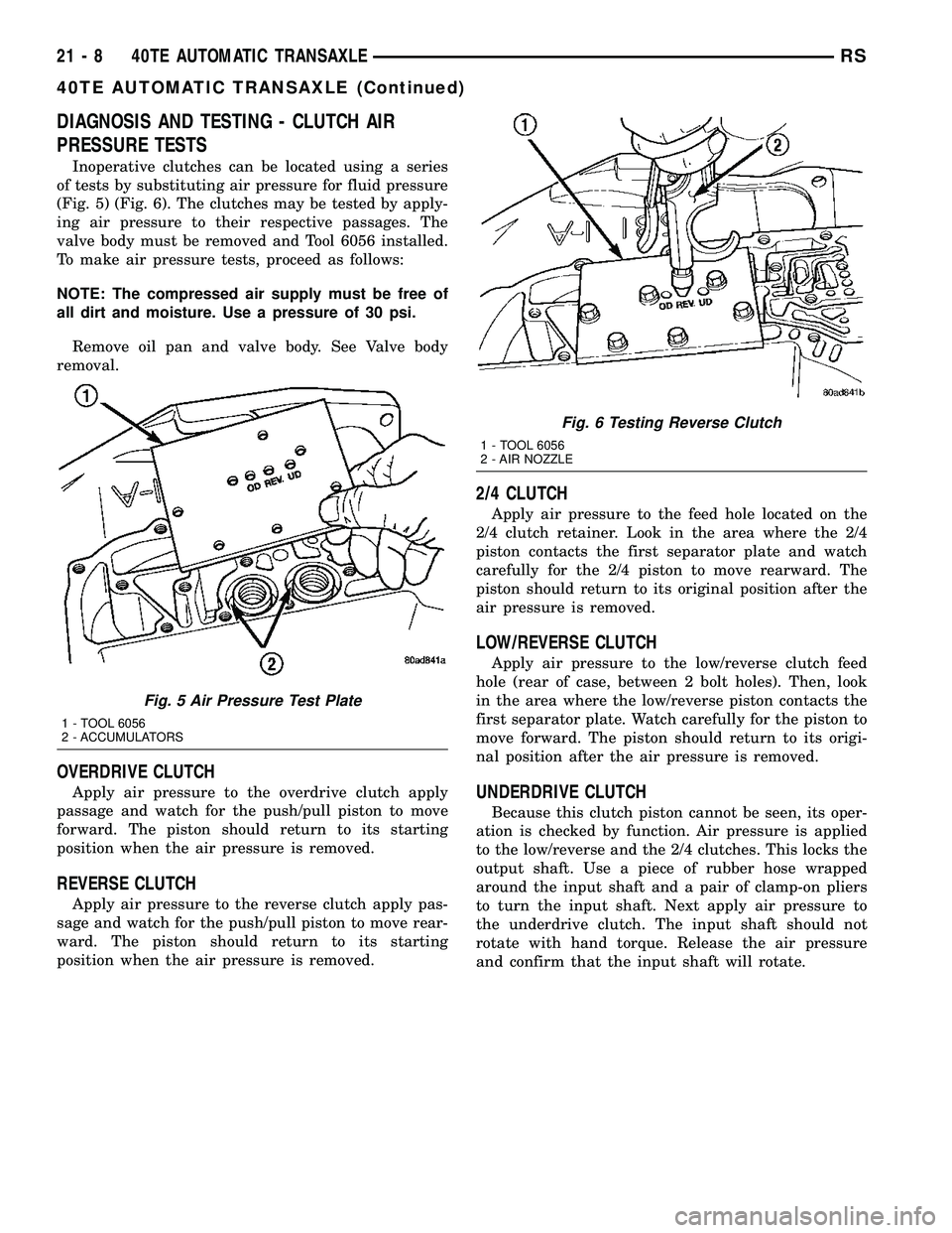
DIAGNOSIS AND TESTING - CLUTCH AIR
PRESSURE TESTS
Inoperative clutches can be located using a series
of tests by substituting air pressure for fluid pressure
(Fig. 5) (Fig. 6). The clutches may be tested by apply-
ing air pressure to their respective passages. The
valve body must be removed and Tool 6056 installed.
To make air pressure tests, proceed as follows:
NOTE: The compressed air supply must be free of
all dirt and moisture. Use a pressure of 30 psi.
Remove oil pan and valve body. See Valve body
removal.
OVERDRIVE CLUTCH
Apply air pressure to the overdrive clutch apply
passage and watch for the push/pull piston to move
forward. The piston should return to its starting
position when the air pressure is removed.
REVERSE CLUTCH
Apply air pressure to the reverse clutch apply pas-
sage and watch for the push/pull piston to move rear-
ward. The piston should return to its starting
position when the air pressure is removed.
2/4 CLUTCH
Apply air pressure to the feed hole located on the
2/4 clutch retainer. Look in the area where the 2/4
piston contacts the first separator plate and watch
carefully for the 2/4 piston to move rearward. The
piston should return to its original position after the
air pressure is removed.
LOW/REVERSE CLUTCH
Apply air pressure to the low/reverse clutch feed
hole (rear of case, between 2 bolt holes). Then, look
in the area where the low/reverse piston contacts the
first separator plate. Watch carefully for the piston to
move forward. The piston should return to its origi-
nal position after the air pressure is removed.
UNDERDRIVE CLUTCH
Because this clutch piston cannot be seen, its oper-
ation is checked by function. Air pressure is applied
to the low/reverse and the 2/4 clutches. This locks the
output shaft. Use a piece of rubber hose wrapped
around the input shaft and a pair of clamp-on pliers
to turn the input shaft. Next apply air pressure to
the underdrive clutch. The input shaft should not
rotate with hand torque. Release the air pressure
and confirm that the input shaft will rotate.
Fig. 5 Air Pressure Test Plate
1 - TOOL 6056
2 - ACCUMULATORS
Fig. 6 Testing Reverse Clutch
1 - TOOL 6056
2 - AIR NOZZLE
21 - 8 40TE AUTOMATIC TRANSAXLERS
40TE AUTOMATIC TRANSAXLE (Continued)
Page 1614 of 2339
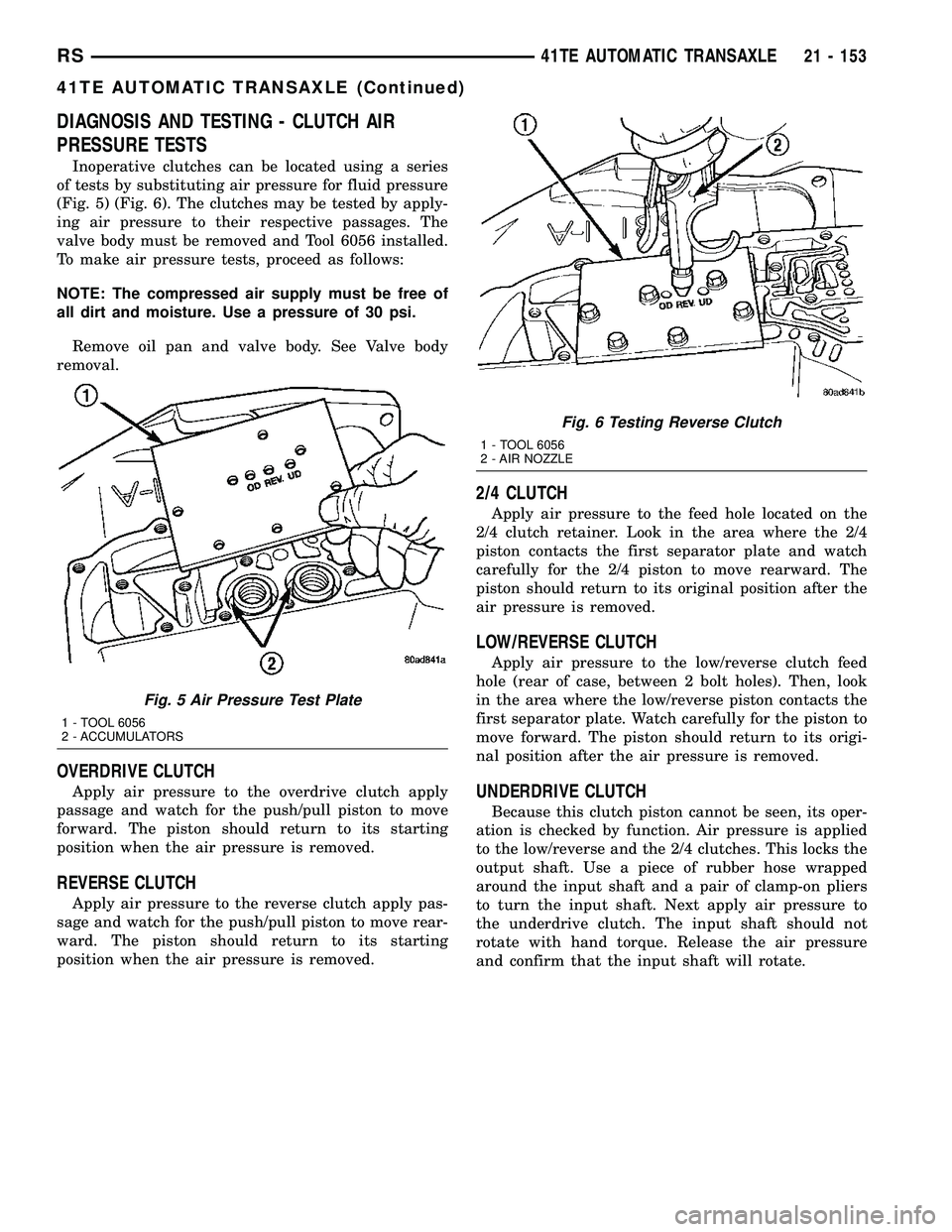
DIAGNOSIS AND TESTING - CLUTCH AIR
PRESSURE TESTS
Inoperative clutches can be located using a series
of tests by substituting air pressure for fluid pressure
(Fig. 5) (Fig. 6). The clutches may be tested by apply-
ing air pressure to their respective passages. The
valve body must be removed and Tool 6056 installed.
To make air pressure tests, proceed as follows:
NOTE: The compressed air supply must be free of
all dirt and moisture. Use a pressure of 30 psi.
Remove oil pan and valve body. See Valve body
removal.
OVERDRIVE CLUTCH
Apply air pressure to the overdrive clutch apply
passage and watch for the push/pull piston to move
forward. The piston should return to its starting
position when the air pressure is removed.
REVERSE CLUTCH
Apply air pressure to the reverse clutch apply pas-
sage and watch for the push/pull piston to move rear-
ward. The piston should return to its starting
position when the air pressure is removed.
2/4 CLUTCH
Apply air pressure to the feed hole located on the
2/4 clutch retainer. Look in the area where the 2/4
piston contacts the first separator plate and watch
carefully for the 2/4 piston to move rearward. The
piston should return to its original position after the
air pressure is removed.
LOW/REVERSE CLUTCH
Apply air pressure to the low/reverse clutch feed
hole (rear of case, between 2 bolt holes). Then, look
in the area where the low/reverse piston contacts the
first separator plate. Watch carefully for the piston to
move forward. The piston should return to its origi-
nal position after the air pressure is removed.
UNDERDRIVE CLUTCH
Because this clutch piston cannot be seen, its oper-
ation is checked by function. Air pressure is applied
to the low/reverse and the 2/4 clutches. This locks the
output shaft. Use a piece of rubber hose wrapped
around the input shaft and a pair of clamp-on pliers
to turn the input shaft. Next apply air pressure to
the underdrive clutch. The input shaft should not
rotate with hand torque. Release the air pressure
and confirm that the input shaft will rotate.
Fig. 5 Air Pressure Test Plate
1 - TOOL 6056
2 - ACCUMULATORS
Fig. 6 Testing Reverse Clutch
1 - TOOL 6056
2 - AIR NOZZLE
RS41TE AUTOMATIC TRANSAXLE21 - 153
41TE AUTOMATIC TRANSAXLE (Continued)