parking brake CHRYSLER CARAVAN 2005 Service Manual
[x] Cancel search | Manufacturer: CHRYSLER, Model Year: 2005, Model line: CARAVAN, Model: CHRYSLER CARAVAN 2005Pages: 2339, PDF Size: 59.69 MB
Page 6 of 2339
FASTENER USAGE
DESCRIPTION
FASTENER USAGE
WARNING: USE OF AN INCORRECT FASTENER
MAY RESULT IN COMPONENT DAMAGE OR PER-
SONAL INJURY.
Fasteners and torque specifications references in
this Service Manual are identified in metric and SAE
format.
During any maintenance or repair procedures, it is
important to salvage all fasteners (nuts, bolts, etc.)
for reassembly. If the fastener is not salvageable, a
fastener of equivalent specification must be used.
THREADED HOLE REPAIR
Most stripped threaded holes can be repaired using
a Helicoilt. Follow the vehicle or Helicoiltrecommen-
dations for application and repair procedures.
INTERNATIONAL SYMBOLS
DESCRIPTION
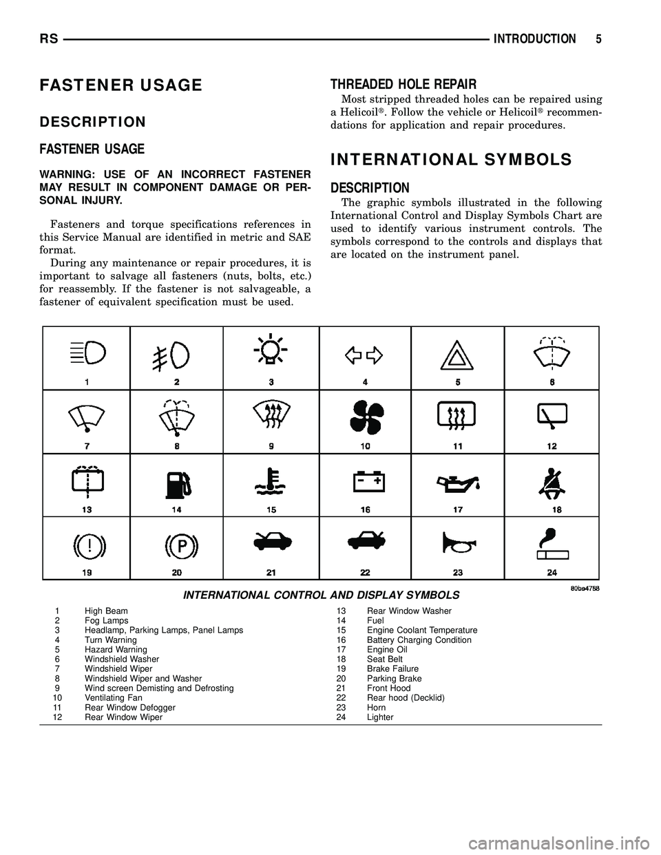
The graphic symbols illustrated in the following
International Control and Display Symbols Chart are
used to identify various instrument controls. The
symbols correspond to the controls and displays that
are located on the instrument panel.
INTERNATIONAL CONTROL AND DISPLAY SYMBOLS
1 High Beam 13 Rear Window Washer
2 Fog Lamps 14 Fuel
3 Headlamp, Parking Lamps, Panel Lamps 15 Engine Coolant Temperature
4 Turn Warning 16 Battery Charging Condition
5 Hazard Warning 17 Engine Oil
6 Windshield Washer 18 Seat Belt
7 Windshield Wiper 19 Brake Failure
8 Windshield Wiper and Washer 20 Parking Brake
9 Wind screen Demisting and Defrosting 21 Front Hood
10 Ventilating Fan 22 Rear hood (Decklid)
11 Rear Window Defogger 23 Horn
12 Rear Window Wiper 24 Lighter
RSINTRODUCTION5
Page 38 of 2339
JUMP STARTING
STANDARD PROCEDURE - JUMP STARTING
WARNING: REVIEW ALL SAFETY PRECAUTIONS
AND WARNINGS. (Refer to 8 - ELECTRICAL/BAT-
TERY SYSTEM/BATTERY - STANDARD PROCE-
DURE).
WARNING: DO NOT JUMP START A FROZEN BAT-
TERY, PERSONAL INJURY CAN RESULT.
WARNING: DO NOT JUMP START WHEN MAINTE-
NANCE FREE BATTERY INDICATOR DOT IS BRIGHT
COLOR.
WARNING: DO NOT ALLOW JUMPER CABLE
CLAMPS TO TOUCH EACH OTHER WHEN CON-
NECTED TO A BOOSTER SOURCE.
WARNING: DO NOT USE OPEN FLAME NEAR BAT-
TERYWARNING: REMOVE METALLIC JEWELRY WORN
ON HANDS OR WRISTS TO AVOID INJURY BY
ACCIDENTAL ARCING OF BATTERY CURRENT.
WARNING: WHEN USING A HIGH OUTPUT BOOST-
ING DEVICE, DO NOT ALLOW BATTERY VOLTAGE
TO EXCEED 16 VOLTS.
WARNING: REFER TO INSTRUCTIONS PROVIDED
WITH DEVICE BEING USED.
CAUTION: DO NOT ATTEMPT TO PUSH OR TOW
THE VEHICLE TO START IT. THE VEHICLE CANNOT
BE STARTED THIS WAY. PUSHING WITH ANOTHER
VEHICLE MAY DAMAGE THE TRANSAXLE OR THE
REAR OF THE VEHICLE.
(1) Raise hood on disabled vehicle and visually
inspect engine compartment for:
²Battery cable clamp condition, clean if necessary.
²Frozen battery.
²Clear or bright color test indicator, if equipped.
²Generator drive belt condition and tension.
²Fuel fumes or leakage, correct if necessary.
CAUTION: If the cause of starting problem on dis-
abled vehicle is severe, damage to booster vehicle
charging system can result.
(2) When using another vehicle as a booster
source, park the booster vehicle within cable reach.
Turn off all accessories, set the parking brake, place
the automatic transmission in PARK or the manual
transmission in NEUTRAL and turn the ignition
OFF.
(3) On disabled vehicle, place gear selector in park
or neutral and set park brake. Turn off all accesso-
ries.
(4) Connect jumper cables to booster battery. RED
clamp to positive terminal (+). BLACK clamp to neg-
ative terminal (-). DO NOT allow clamps at opposite
end of cables to touch, electrical arc will result.
Review all warnings in this procedure.
(5) On disabled vehicle, connect RED jumper cable
clamp to positive (+) terminal. Connect BLACK
jumper cable clamp to engine ground as close to the
ground cable attaching point as possible (Fig. 6).
(Refer to 8 - ELECTRICAL/BATTERY SYSTEM/BAT-
TERY - STANDARD PROCEDURE).
(6) Start the engine in the vehicle which has the
booster battery, let the engine idle a few minutes,
then start the engine in the vehicle with the dis-
charged battery.
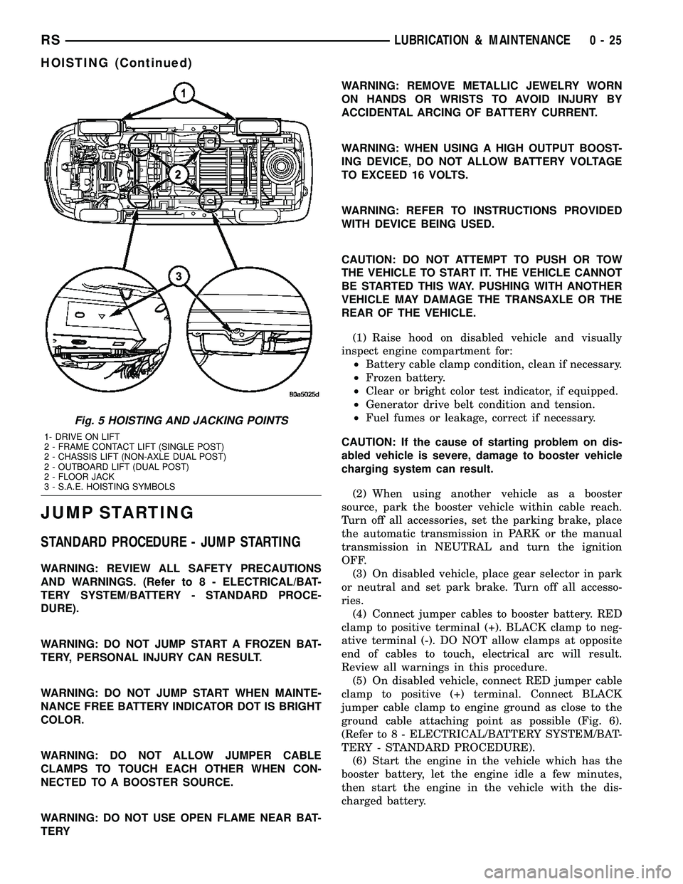
Fig. 5 HOISTING AND JACKING POINTS
1- DRIVE ON LIFT
2 - FRAME CONTACT LIFT (SINGLE POST)
2 - CHASSIS LIFT (NON-AXLE DUAL POST)
2 - OUTBOARD LIFT (DUAL POST)
2 - FLOOR JACK
3 - S.A.E. HOISTING SYMBOLS
RSLUBRICATION & MAINTENANCE0-25
HOISTING (Continued)
Page 73 of 2339
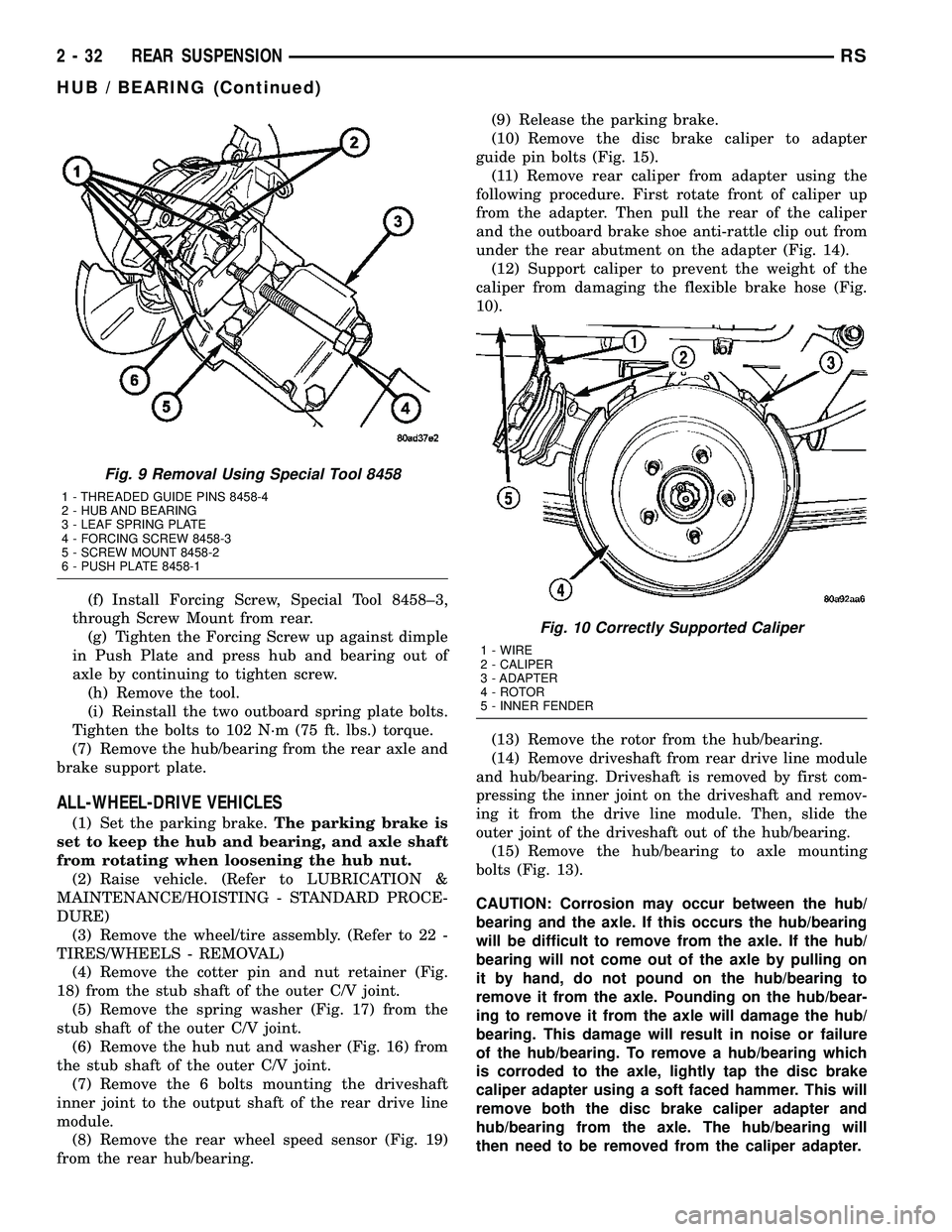
(f) Install Forcing Screw, Special Tool 8458±3,
through Screw Mount from rear.
(g) Tighten the Forcing Screw up against dimple
in Push Plate and press hub and bearing out of
axle by continuing to tighten screw.
(h) Remove the tool.
(i) Reinstall the two outboard spring plate bolts.
Tighten the bolts to 102 N´m (75 ft. lbs.) torque.
(7) Remove the hub/bearing from the rear axle and
brake support plate.
ALL-WHEEL-DRIVE VEHICLES
(1) Set the parking brake.The parking brake is
set to keep the hub and bearing, and axle shaft
from rotating when loosening the hub nut.
(2) Raise vehicle. (Refer to LUBRICATION &
MAINTENANCE/HOISTING - STANDARD PROCE-
DURE)
(3) Remove the wheel/tire assembly. (Refer to 22 -
TIRES/WHEELS - REMOVAL)
(4) Remove the cotter pin and nut retainer (Fig.
18) from the stub shaft of the outer C/V joint.
(5) Remove the spring washer (Fig. 17) from the
stub shaft of the outer C/V joint.
(6) Remove the hub nut and washer (Fig. 16) from
the stub shaft of the outer C/V joint.
(7) Remove the 6 bolts mounting the driveshaft
inner joint to the output shaft of the rear drive line
module.
(8) Remove the rear wheel speed sensor (Fig. 19)
from the rear hub/bearing.(9) Release the parking brake.
(10) Remove the disc brake caliper to adapter
guide pin bolts (Fig. 15).
(11) Remove rear caliper from adapter using the
following procedure. First rotate front of caliper up
from the adapter. Then pull the rear of the caliper
and the outboard brake shoe anti-rattle clip out from
under the rear abutment on the adapter (Fig. 14).
(12) Support caliper to prevent the weight of the
caliper from damaging the flexible brake hose (Fig.
10).
(13) Remove the rotor from the hub/bearing.
(14)
Remove driveshaft from rear drive line module
and hub/bearing. Driveshaft is removed by first com-
pressing the inner joint on the driveshaft and remov-
ing it from the drive line module. Then, slide the
outer joint of the driveshaft out of the hub/bearing.
(15) Remove the hub/bearing to axle mounting
bolts (Fig. 13).
CAUTION: Corrosion may occur between the hub/
bearing and the axle. If this occurs the hub/bearing
will be difficult to remove from the axle. If the hub/
bearing will not come out of the axle by pulling on
it by hand, do not pound on the hub/bearing to
remove it from the axle. Pounding on the hub/bear-
ing to remove it from the axle will damage the hub/
bearing. This damage will result in noise or failure
of the hub/bearing. To remove a hub/bearing which
is corroded to the axle, lightly tap the disc brake
caliper adapter using a soft faced hammer. This will
remove both the disc brake caliper adapter and
hub/bearing from the axle. The hub/bearing will
then need to be removed from the caliper adapter.
Fig. 9 Removal Using Special Tool 8458
1 - THREADED GUIDE PINS 8458-4
2 - HUB AND BEARING
3 - LEAF SPRING PLATE
4 - FORCING SCREW 8458-3
5 - SCREW MOUNT 8458-2
6 - PUSH PLATE 8458-1
Fig. 10 Correctly Supported Caliper
1 - WIRE
2 - CALIPER
3 - ADAPTER
4 - ROTOR
5 - INNER FENDER
2 - 32 REAR SUSPENSIONRS
HUB / BEARING (Continued)
Page 113 of 2339

DISASSEMBLY - CALIPER PISTON AND
SEAL...............................24
CLEANING - CALIPER...................25
INSPECTION - CALIPER..................25
ASSEMBLY
ASSEMBLY - CALIPER GUIDE PIN
BUSHINGS (CONTINENTAL TEVES
BRAKES)............................25
ASSEMBLY - CALIPER PISTON AND SEAL . . 26
INSTALLATION
INSTALLATION - FRONT DISC BRAKE
CALIPER (CONTINENTAL TEVES
BRAKES)............................27
INSTALLATION - FRONT DISC BRAKE
CALIPER (TRW BRAKES)...............27
DISC BRAKE CALIPER - REAR
REMOVAL - REAR DISC BRAKE CALIPER....28
DISASSEMBLY - CALIPER PISTON AND SEAL..28
CLEANING - CALIPER...................29
INSPECTION - CALIPER..................29
ASSEMBLY - CALIPER PISTON AND SEAL . . . 30
INSTALLATION - REAR DISC BRAKE CALIPER..30
DISC BRAKE CALIPER ADAPTER
REMOVAL - FRONT DISC BRAKE CALIPER
ADAPTER...........................31
INSTALLATION - FRONT DISC BRAKE
CALIPER ADAPTER....................31
DISC BRAKE CALIPER GUIDE PINS
REMOVAL - DISC BRAKE CALIPER GUIDE
PINS (TRW BRAKES)..................31
INSTALLATION - DISC BRAKE CALIPER
GUIDE PINS (TRW BRAKES).............32
DRUM
REMOVAL.............................32
INSTALLATION.........................32
FLUID
DIAGNOSIS AND TESTING - BRAKE FLUID
CONTAMINATION.....................33
STANDARD PROCEDURE - BRAKE FLUID
LEVEL CHECKING.....................33
SPECIFICATIONS
BRAKE FLUID........................33
JUNCTION BLOCK
DESCRIPTION - NON-ABS JUNCTION BLOCK..33
OPERATION - NON-ABS JUNCTION BLOCK . . 33
REMOVAL - NON-ABS JUNCTION BLOCK....34
INSTALLATION - NON-ABS JUNCTION BLOCK..34
MASTER CYLINDER
DESCRIPTION
DESCRIPTION........................35
DESCRIPTION - RHD..................35
OPERATION...........................36
STANDARD PROCEDURE - MASTER
CYLINDER BLEEDING..................36
REMOVAL
REMOVAL - LHD......................36
REMOVAL - RHD......................37DISASSEMBLY - MASTER CYLINDER (FLUID
RESERVOIR).........................38
ASSEMBLY - MASTER CYLINDER (FLUID
RESERVOIR).........................39
INSTALLATION
INSTALLATION - LHD..................39
INSTALLATION - RHD..................39
PEDALS - ADJUSTABLE
REMOVAL.............................40
INSTALLATION.........................43
PEDAL TORQUE SHAFT - RHD
REMOVAL.............................44
INSTALLATION.........................44
POWER BRAKE BOOSTER
DESCRIPTION.........................45
OPERATION...........................46
DIAGNOSIS AND TESTING - POWER BRAKE
BOOSTER...........................46
REMOVAL
REMOVAL - LHD......................46
REMOVAL - RHD......................48
INSTALLATION
INSTALLATION - LHD..................50
INSTALLATION - RHD..................51
PROPORTIONING VALVE
DESCRIPTION - PROPORTIONING VALVE
(HEIGHT SENSING)....................53
OPERATION - PROPORTIONING VALVE
(HEIGHT SENSING)....................53
DIAGNOSIS AND TESTING -
PROPORTIONING VALVE (HEIGHT
SENSING)...........................54
REMOVAL - PROPORTIONING VALVE
(HEIGHT SENSING)....................55
INSTALLATION - PROPORTIONING VALVE
(HEIGHT SENSING)....................55
ROTOR
DIAGNOSIS AND TESTING - BRAKE ROTOR . . 55
STANDARD PROCEDURE - BRAKE ROTOR
MACHINING..........................58
REMOVAL - FRONT BRAKE ROTOR........59
INSTALLATION - FRONT BRAKE ROTOR.....59
SPECIFICATIONS
BRAKE ROTOR.......................60
BRAKE ROTOR - EXPORT..............60
SUPPORT PLATE - DRUM BRAKE
REMOVAL.............................61
INSTALLATION.........................61
WHEEL CYLINDERS
REMOVAL.............................62
INSPECTION..........................62
INSTALLATION.........................62
PARKING BRAKE
DESCRIPTION
DESCRIPTION........................62
DESCRIPTION - EXPORT...............63
OPERATION...........................63
5 - 2 BRAKES - BASERS
Page 114 of 2339
STANDARD PROCEDURE
STANDARD PROCEDURE - PARKING
BRAKE AUTOMATIC ADJUSTER TENSION
RELEASE...........................63
STANDARD PROCEDURE - PARKING
BRAKE AUTOMATIC ADJUSTER TENSION
RESET.............................64
STANDARD PROCEDURE - CABLE END
CLEANING AND LUBRICATION...........65
ADJUSTMENTS
ADJUSTMENT - PARKING BRAKE
CABLES............................65
CABLE - PARKING BRAKE FRONT
REMOVAL
REMOVAL...........................66
REMOVAL - FOLD-IN-FLOOR SEATING.....66
REMOVAL - EXPORT..................67
INSTALLATION
INSTALLATION.......................67
INSTALLATION - FOLD-IN-FLOOR SEATING . 68
INSTALLATION - EXPORT...............68
CABLE - PARKING BRAKE INTERMEDIATE
REMOVAL.............................69
INSTALLATION.........................69CABLE - PARKING BRAKE REAR
REMOVAL
REMOVAL - RIGHT REAR...............70
REMOVAL - LEFT REAR................71
REMOVAL - FOLD-IN-FLOOR SEATING.....72
INSTALLATION
INSTALLATION - RIGHT REAR...........74
INSTALLATION - LEFT REAR............75
INSTALLATION - FOLD-IN-FLOOR
SEATING............................75
LEVER - PARKING BRAKE
REMOVAL.............................75
INSTALLATION.........................76
LEVER - PARKING BRAKE (EXPORT)
REMOVAL - PARKING BRAKE LEVER AND
FRONT CABLE.......................77
INSTALLATION - PARKING BRAKE LEVER
AND FRONT CABLE...................77
SHOES - PARKING BRAKE
REMOVAL.............................78
INSTALLATION.........................84
ADJUSTMENTS
ADJUSTMENT - PARKING BRAKE SHOES . . 85
BRAKES - BASE
DESCRIPTION
DESCRIPTION - BASE BRAKES
The base brake system consists of the following
components:
²Brake pedal
²Power brake booster
²Master cylinder
²Brake tubes and hoses
²Proportioning valve (non-ABS vehicles only)
²Disc brakes
²Drum brakes
²Brake lamp switch
²Brake fluid level switch
²Parking brakes
Front disc brakes control the braking of the front
wheels; rear braking is controlled by rear drum
brakes or rear disc brakes depending on options.
The hydraulic brake system is diagonally split on
both the non-antilock braking systems and antilock
braking systems. That means the left front and right
rear brakes are on one hydraulic circuit and the right
front and left rear are on the other.
For information on the brake lamp switch, (Refer
to 8 - ELECTRICAL/LAMPS/LIGHTING - EXTERI-
OR/BRAKE LAMP SWITCH - DESCRIPTION)Vehicles equipped with the optional antilock brake
system (ABS) use a system designated Mark 20e. It
is available with or without traction control. This
system shares most base brake hardware used on
vehicles without ABS. ABS components are described
in detail in ANTILOCK BRAKE SYSTEM.DESCRIPTION - BASE BRAKES (EXPORT)
Four-Wheel Disc Antilock Brakes are standard on
all models.
OPERATION - BASE BRAKES
When a vehicle needs to be stopped, the driver
applies the brake pedal. The brake pedal pushes the
input rod of the power brake booster into the booster.
The booster uses vacuum to ease pedal effort as force
is transferred through the booster to the master cyl-
inder. The booster's output rod pushes in the master
cylinder's primary and secondary pistons applying
hydraulic pressure through the chassis brake tubes
to the brakes at each tire and wheel assembly.
The parking brakes are foot-operated. When
applied, the parking brake lever pulls on cables that
actuate brake shoes at each rear wheel. These shoes
come in contact with a hub mounted drum (drum for
disc/drum brakes or drum-in-hat for disc/disc brakes)
and hold it in place.
RSBRAKES - BASE5-3
Page 115 of 2339
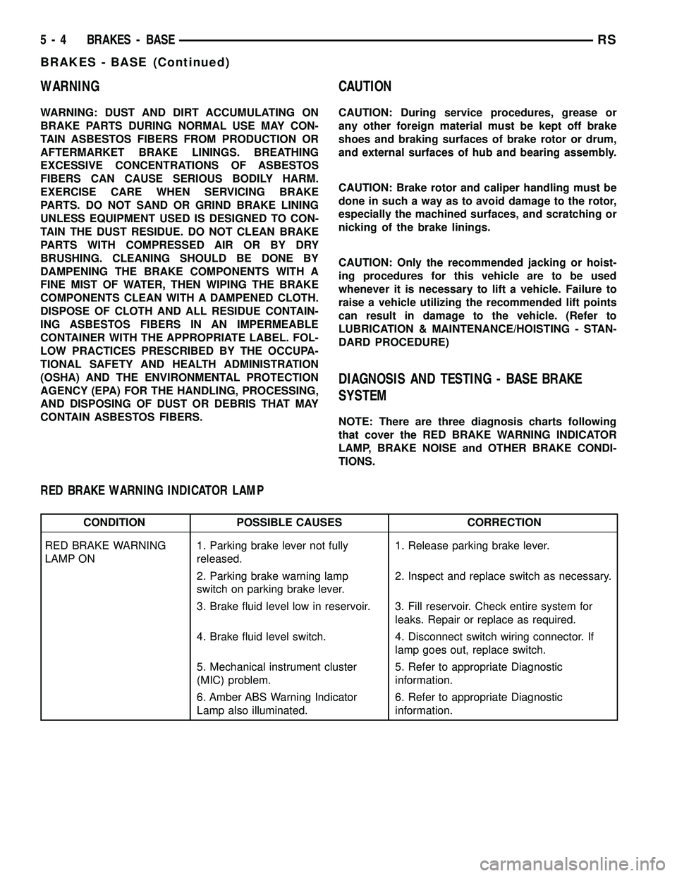
WARNING
WARNING: DUST AND DIRT ACCUMULATING ON
BRAKE PARTS DURING NORMAL USE MAY CON-
TAIN ASBESTOS FIBERS FROM PRODUCTION OR
AFTERMARKET BRAKE LININGS. BREATHING
EXCESSIVE CONCENTRATIONS OF ASBESTOS
FIBERS CAN CAUSE SERIOUS BODILY HARM.
EXERCISE CARE WHEN SERVICING BRAKE
PARTS. DO NOT SAND OR GRIND BRAKE LINING
UNLESS EQUIPMENT USED IS DESIGNED TO CON-
TAIN THE DUST RESIDUE. DO NOT CLEAN BRAKE
PARTS WITH COMPRESSED AIR OR BY DRY
BRUSHING. CLEANING SHOULD BE DONE BY
DAMPENING THE BRAKE COMPONENTS WITH A
FINE MIST OF WATER, THEN WIPING THE BRAKE
COMPONENTS CLEAN WITH A DAMPENED CLOTH.
DISPOSE OF CLOTH AND ALL RESIDUE CONTAIN-
ING ASBESTOS FIBERS IN AN IMPERMEABLE
CONTAINER WITH THE APPROPRIATE LABEL. FOL-
LOW PRACTICES PRESCRIBED BY THE OCCUPA-
TIONAL SAFETY AND HEALTH ADMINISTRATION
(OSHA) AND THE ENVIRONMENTAL PROTECTION
AGENCY (EPA) FOR THE HANDLING, PROCESSING,
AND DISPOSING OF DUST OR DEBRIS THAT MAY
CONTAIN ASBESTOS FIBERS.
CAUTION
CAUTION: During service procedures, grease or
any other foreign material must be kept off brake
shoes and braking surfaces of brake rotor or drum,
and external surfaces of hub and bearing assembly.
CAUTION: Brake rotor and caliper handling must be
done in such a way as to avoid damage to the rotor,
especially the machined surfaces, and scratching or
nicking of the brake linings.
CAUTION: Only the recommended jacking or hoist-
ing procedures for this vehicle are to be used
whenever it is necessary to lift a vehicle. Failure to
raise a vehicle utilizing the recommended lift points
can result in damage to the vehicle. (Refer to
LUBRICATION & MAINTENANCE/HOISTING - STAN-
DARD PROCEDURE)
DIAGNOSIS AND TESTING - BASE BRAKE
SYSTEM
NOTE: There are three diagnosis charts following
that cover the RED BRAKE WARNING INDICATOR
LAMP, BRAKE NOISE and OTHER BRAKE CONDI-
TIONS.
RED BRAKE WARNING INDICATOR LAMP
CONDITION POSSIBLE CAUSES CORRECTION
RED BRAKE WARNING
LAMP ON1. Parking brake lever not fully
released.1. Release parking brake lever.
2. Parking brake warning lamp
switch on parking brake lever.2. Inspect and replace switch as necessary.
3. Brake fluid level low in reservoir. 3. Fill reservoir. Check entire system for
leaks. Repair or replace as required.
4. Brake fluid level switch. 4. Disconnect switch wiring connector. If
lamp goes out, replace switch.
5. Mechanical instrument cluster
(MIC) problem.5. Refer to appropriate Diagnostic
information.
6. Amber ABS Warning Indicator
Lamp also illuminated.6. Refer to appropriate Diagnostic
information.
5 - 4 BRAKES - BASERS
BRAKES - BASE (Continued)
Page 117 of 2339
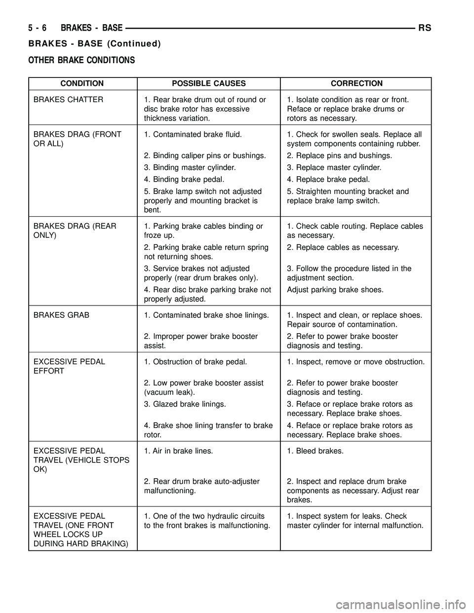
OTHER BRAKE CONDITIONS
CONDITION POSSIBLE CAUSES CORRECTION
BRAKES CHATTER 1. Rear brake drum out of round or
disc brake rotor has excessive
thickness variation.1. Isolate condition as rear or front.
Reface or replace brake drums or
rotors as necessary.
BRAKES DRAG (FRONT
OR ALL)1. Contaminated brake fluid. 1. Check for swollen seals. Replace all
system components containing rubber.
2. Binding caliper pins or bushings. 2. Replace pins and bushings.
3. Binding master cylinder. 3. Replace master cylinder.
4. Binding brake pedal. 4. Replace brake pedal.
5. Brake lamp switch not adjusted
properly and mounting bracket is
bent.5. Straighten mounting bracket and
replace brake lamp switch.
BRAKES DRAG (REAR
ONLY)1. Parking brake cables binding or
froze up.1. Check cable routing. Replace cables
as necessary.
2. Parking brake cable return spring
not returning shoes.2. Replace cables as necessary.
3. Service brakes not adjusted
properly (rear drum brakes only).3. Follow the procedure listed in the
adjustment section.
4. Rear disc brake parking brake not
properly adjusted.Adjust parking brake shoes.
BRAKES GRAB 1. Contaminated brake shoe linings. 1. Inspect and clean, or replace shoes.
Repair source of contamination.
2. Improper power brake booster
assist.2. Refer to power brake booster
diagnosis and testing.
EXCESSIVE PEDAL
EFFORT1. Obstruction of brake pedal. 1. Inspect, remove or move obstruction.
2. Low power brake booster assist
(vacuum leak).2. Refer to power brake booster
diagnosis and testing.
3. Glazed brake linings. 3. Reface or replace brake rotors as
necessary. Replace brake shoes.
4. Brake shoe lining transfer to brake
rotor.4. Reface or replace brake rotors as
necessary. Replace brake shoes.
EXCESSIVE PEDAL
TRAVEL (VEHICLE STOPS
OK)1. Air in brake lines. 1. Bleed brakes.
2. Rear drum brake auto-adjuster
malfunctioning.2. Inspect and replace drum brake
components as necessary. Adjust rear
brakes.
EXCESSIVE PEDAL
TRAVEL (ONE FRONT
WHEEL LOCKS UP
DURING HARD BRAKING)1. One of the two hydraulic circuits
to the front brakes is malfunctioning.1. Inspect system for leaks. Check
master cylinder for internal malfunction.
5 - 6 BRAKES - BASERS
BRAKES - BASE (Continued)
Page 118 of 2339
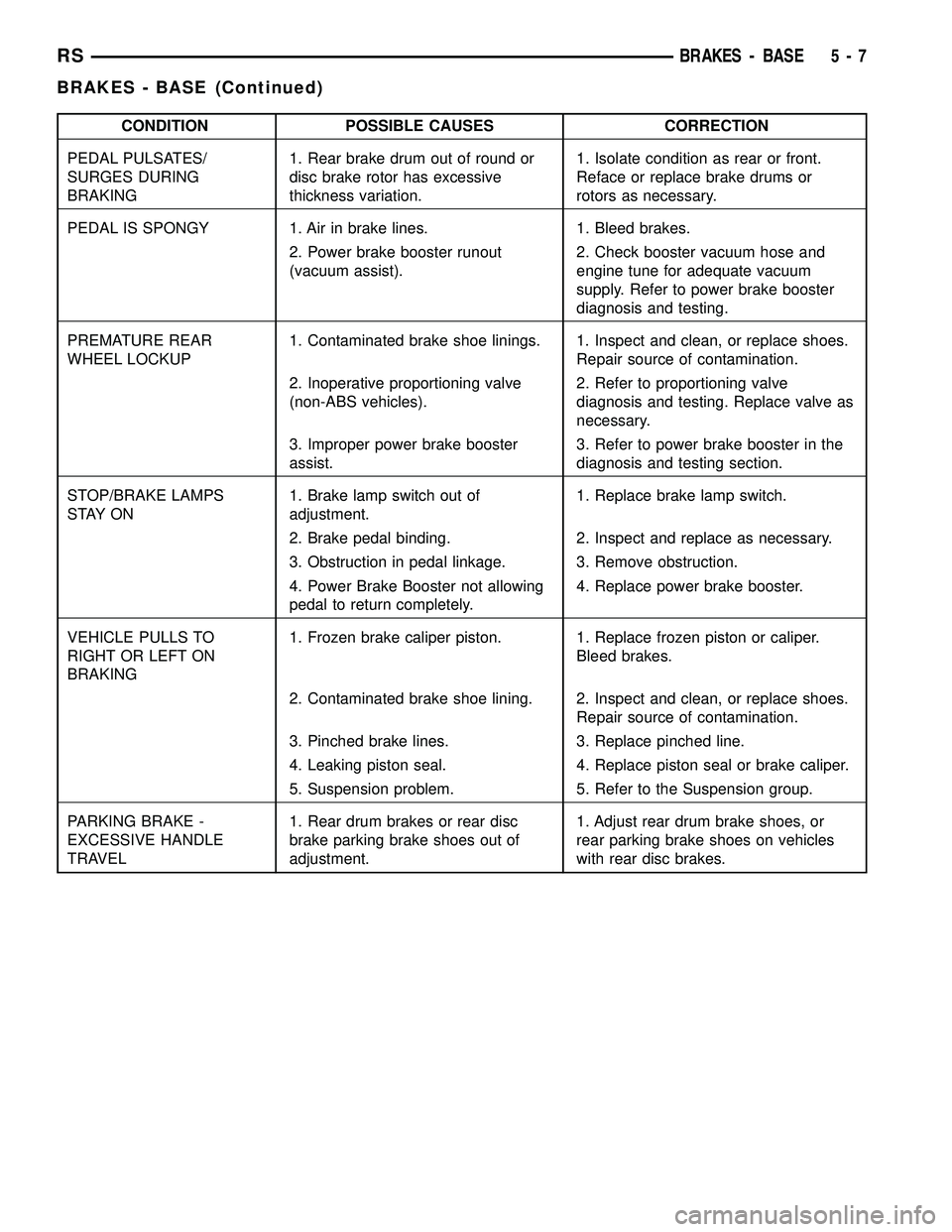
CONDITION POSSIBLE CAUSES CORRECTION
PEDAL PULSATES/
SURGES DURING
BRAKING1. Rear brake drum out of round or
disc brake rotor has excessive
thickness variation.1. Isolate condition as rear or front.
Reface or replace brake drums or
rotors as necessary.
PEDAL IS SPONGY 1. Air in brake lines. 1. Bleed brakes.
2. Power brake booster runout
(vacuum assist).2. Check booster vacuum hose and
engine tune for adequate vacuum
supply. Refer to power brake booster
diagnosis and testing.
PREMATURE REAR
WHEEL LOCKUP1. Contaminated brake shoe linings. 1. Inspect and clean, or replace shoes.
Repair source of contamination.
2. Inoperative proportioning valve
(non-ABS vehicles).2. Refer to proportioning valve
diagnosis and testing. Replace valve as
necessary.
3. Improper power brake booster
assist.3. Refer to power brake booster in the
diagnosis and testing section.
STOP/BRAKE LAMPS
S TAY O N1. Brake lamp switch out of
adjustment.1. Replace brake lamp switch.
2. Brake pedal binding. 2. Inspect and replace as necessary.
3. Obstruction in pedal linkage. 3. Remove obstruction.
4. Power Brake Booster not allowing
pedal to return completely.4. Replace power brake booster.
VEHICLE PULLS TO
RIGHT OR LEFT ON
BRAKING1. Frozen brake caliper piston. 1. Replace frozen piston or caliper.
Bleed brakes.
2. Contaminated brake shoe lining. 2. Inspect and clean, or replace shoes.
Repair source of contamination.
3. Pinched brake lines. 3. Replace pinched line.
4. Leaking piston seal. 4. Replace piston seal or brake caliper.
5. Suspension problem. 5. Refer to the Suspension group.
PARKING BRAKE -
EXCESSIVE HANDLE
TRAVEL1. Rear drum brakes or rear disc
brake parking brake shoes out of
adjustment.1. Adjust rear drum brake shoes, or
rear parking brake shoes on vehicles
with rear disc brakes.
RSBRAKES - BASE5-7
BRAKES - BASE (Continued)
Page 120 of 2339
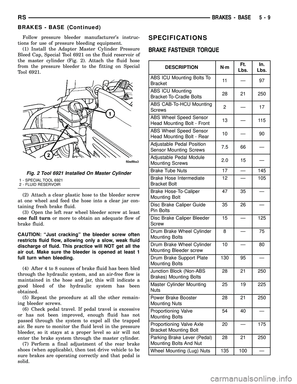
Follow pressure bleeder manufacturer's instruc-
tions for use of pressure bleeding equipment.
(1) Install the Adapter Master Cylinder Pressure
Bleed Cap, Special Tool 6921 on the fluid reservoir of
the master cylinder (Fig. 2). Attach the fluid hose
from the pressure bleeder to the fitting on Special
Tool 6921.
(2) Attach a clear plastic hose to the bleeder screw
at one wheel and feed the hose into a clear jar con-
taining fresh brake fluid.
(3) Open the left rear wheel bleeder screw at least
one full turnor more to obtain an adequate flow of
brake fluid.
CAUTION: ªJust crackingº the bleeder screw often
restricts fluid flow, allowing only a slow, weak fluid
discharge of fluid. This practice will NOT get all the
air out. Make sure the bleeder is opened at least 1
full turn when bleeding.
(4) After 4 to 8 ounces of brake fluid has been bled
through the hydraulic system, and an air-free flow is
maintained in the hose and jar, this will indicate a
good bleed of the hydraulic system has been
obtained.
(5) Repeat the procedure at all the other remain-
ing bleeder screws.
(6) Check pedal travel. If pedal travel is excessive
or has not been improved, enough fluid has not
passed through the system to expel all the trapped
air. Be sure to monitor the fluid level in the pressure
bleeder, so it stays at a proper level so air will not
enter the brake system through the master cylinder.
(7) Perform a final adjustment of the rear brake
shoes (when applicable), then test drive vehicle to be
sure brakes are operating correctly and that pedal is
solid.SPECIFICATIONS
BRAKE FASTENER TORQUE
DESCRIPTION N´mFt.
Lbs.In.
Lbs.
ABS ICU Mounting Bolts To
Bracket11 Ð 9 7
ABS ICU Mounting
Bracket-To-Cradle Bolts28 21 250
ABS CAB-To-HCU Mounting
Screws2Ð17
ABS Wheel Speed Sensor
Head Mounting Bolt - Front13 Ð 115
ABS Wheel Speed Sensor
Head Mounting Bolt - Rear10 Ð 90
Adjustable Pedal Position
Sensor Mounting Screws7.5 66 Ð
Adjustable Pedal Module
Mounting Screws2.0 15 Ð
Brake Tube Nuts 17 Ð 145
Brake Hose Intermediate
Bracket Bolt12 Ð 105
Brake Hose-To-Caliper
Mounting Bolt47 35 Ð
Disc Brake Caliper Guide
Pin Bolts35 26 Ð
Disc Brake Caliper Bleeder
Screw15 Ð 125
Drum Brake Wheel Cylinder
Mounting Bolts8Ð75
Drum Brake Wheel Cylinder
Mounting Bleeder screw10 Ð 80
Drum Brake Support Plate
Mounting Bolts130 95 Ð
Junction Block (Non-ABS
Brakes) Mounting Bolts28 21 250
Master Cylinder Mounting
Nuts25 19 225
Power Brake Booster
Mounting Nuts28 21 250
Proportioning Valve
Mounting Bolts54 40 Ð
Proportioning Valve Axle
Bracket Mounting Bolt20 Ð 175
Parking Brake Lever (Pedal)
Mounting Bolts And Nut28 21 250
Wheel Mounting (Lug) Nuts 135 100 Ð
Fig. 2 Tool 6921 Installed On Master Cylinder
1 - SPECIAL TOOL 6921
2 - FLUID RESERVOIR
RSBRAKES - BASE5-9
BRAKES - BASE (Continued)
Page 124 of 2339
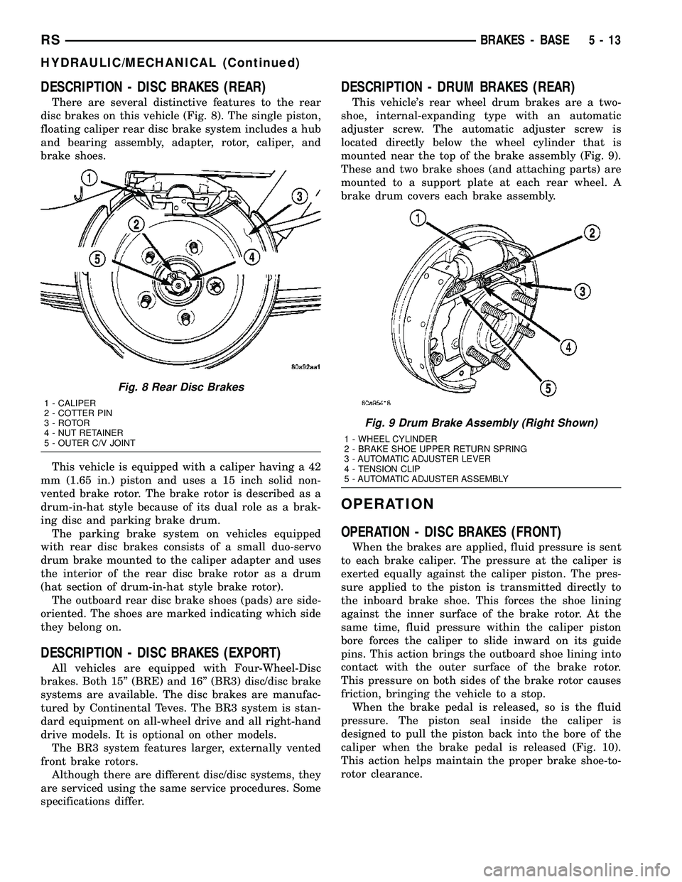
DESCRIPTION - DISC BRAKES (REAR)
There are several distinctive features to the rear
disc brakes on this vehicle (Fig. 8). The single piston,
floating caliper rear disc brake system includes a hub
and bearing assembly, adapter, rotor, caliper, and
brake shoes.
This vehicle is equipped with a caliper having a 42
mm (1.65 in.) piston and uses a 15 inch solid non-
vented brake rotor. The brake rotor is described as a
drum-in-hat style because of its dual role as a brak-
ing disc and parking brake drum.
The parking brake system on vehicles equipped
with rear disc brakes consists of a small duo-servo
drum brake mounted to the caliper adapter and uses
the interior of the rear disc brake rotor as a drum
(hat section of drum-in-hat style brake rotor).
The outboard rear disc brake shoes (pads) are side-
oriented. The shoes are marked indicating which side
they belong on.
DESCRIPTION - DISC BRAKES (EXPORT)
All vehicles are equipped with Four-Wheel-Disc
brakes. Both 15º (BRE) and 16º (BR3) disc/disc brake
systems are available. The disc brakes are manufac-
tured by Continental Teves. The BR3 system is stan-
dard equipment on all-wheel drive and all right-hand
drive models. It is optional on other models.
The BR3 system features larger, externally vented
front brake rotors.
Although there are different disc/disc systems, they
are serviced using the same service procedures. Some
specifications differ.
DESCRIPTION - DRUM BRAKES (REAR)
This vehicle's rear wheel drum brakes are a two-
shoe, internal-expanding type with an automatic
adjuster screw. The automatic adjuster screw is
located directly below the wheel cylinder that is
mounted near the top of the brake assembly (Fig. 9).
These and two brake shoes (and attaching parts) are
mounted to a support plate at each rear wheel. A
brake drum covers each brake assembly.
OPERATION
OPERATION - DISC BRAKES (FRONT)
When the brakes are applied, fluid pressure is sent
to each brake caliper. The pressure at the caliper is
exerted equally against the caliper piston. The pres-
sure applied to the piston is transmitted directly to
the inboard brake shoe. This forces the shoe lining
against the inner surface of the brake rotor. At the
same time, fluid pressure within the caliper piston
bore forces the caliper to slide inward on its guide
pins. This action brings the outboard shoe lining into
contact with the outer surface of the brake rotor.
This pressure on both sides of the brake rotor causes
friction, bringing the vehicle to a stop.
When the brake pedal is released, so is the fluid
pressure. The piston seal inside the caliper is
designed to pull the piston back into the bore of the
caliper when the brake pedal is released (Fig. 10).
This action helps maintain the proper brake shoe-to-
rotor clearance.
Fig. 8 Rear Disc Brakes
1 - CALIPER
2 - COTTER PIN
3 - ROTOR
4 - NUT RETAINER
5 - OUTER C/V JOINT
Fig. 9 Drum Brake Assembly (Right Shown)
1 - WHEEL CYLINDER
2 - BRAKE SHOE UPPER RETURN SPRING
3 - AUTOMATIC ADJUSTER LEVER
4 - TENSION CLIP
5 - AUTOMATIC ADJUSTER ASSEMBLY
RSBRAKES - BASE5-13
HYDRAULIC/MECHANICAL (Continued)