differential CHRYSLER CARAVAN 2005 Service Manual
[x] Cancel search | Manufacturer: CHRYSLER, Model Year: 2005, Model line: CARAVAN, Model: CHRYSLER CARAVAN 2005Pages: 2339, PDF Size: 59.69 MB
Page 1 of 2339
GROUP TAB LOCATOR
Introduction
0Lubrication & Maintenance
2Suspension
3Differential & Driveline
5Brakes
7Cooling
8AAudio
8BChime/Buzzer
8EElectronic Control Modules
8FEngine Systems
8GHeated Systems
8HHorn
8IIgnition Control
8JInstrument Cluster
8LLamps
8MMessage Systems
8NPower Systems
8ORestraints
8PSpeed Control
8QVehicle Theft Security
8RWipers/Washers
8TNavigation/Telecommunication
8WWiring
9Engine
11Exhaust System
13Frame & Bumpers
14Fuel System
19Steering
21Transmission/Transaxle
22Tires/Wheels
23Body
24Heating & Air Conditioning
25Emissions Control
Component and System Index
Service Manual Comment Forms (Rear of Manual)
Page 17 of 2339
For best results, a refueling pattern that alternates
between E-85 and unleaded gasoline should be
avoided. When you do switch fuels, it is recom-
mended that
²you do not switch when the fuel gauge indicates
less than 1/4 full
²you do not add less than 5 gallons when refuel-
ing
²you operate the vehicle immediately after refuel-
ing for a period of at least 5 minutes
Observing these precautions will avoid possible
hard starting and/or significant deterioration in
driveability during warm up.
FFV STARTING
The characteristics of E-85 fuel make it unsuitable
for use when ambient temperatures fall below 0ÉF. In
the range of 0ÉF to 32ÉF, you may experience an
increase in the time it takes for your engine to start,
and a deterioration in driveability (sags and/or hesi-
tations) until the engine is fully warmed up.
Engine Operating on E-85 Fuel
If vehicle operates on E-85 fuel either full or part-
time, use only MopartFlexible Fuel 5W-30 engine oil
or an equivalent that meets DaimlerChrysler Stan-
dard MS-9214. Equivalent commercial Flexible Fuel
engine oils may be labeled as Multi-Fuel, Variable
Fuel, Flexible Fuel, etc. These engine oils may be
satisfactory if they meet the DaimlerChrysler Stan-
dard.
SAE 5W-30 engine oil is preferred for use in Flex-
ible Fuel engines.
CAUTION: If Flexible Fuel engine oil is not used
when using E-85 fuel, engine wear or damage may
result.
CRUISING RANGE
Because E-85 fuel contains less energy per gallon
than gasoline, you will experience an increase in fuel
consumption. You can expect your MPG and your
driving range to decrease by about 30% compared to
gasoline operation.
DESCRIPTION - AUTOMATIC/MANUAL
TRANSAXLE FLUID
NOTE: Refer to the maintenance schedules for the
recommended maintenance (fluid/filter change)
intervals for these transaxles.
NOTE: All transaxles have a common transmission
and differential sump. Filling the transaxle accom-
modates the differential as well.
TRANSMISSION FLUID
MopartATF+4 (Automatic Transmission Fluid) is
required in the 4XTE automatic and T850 manual
transaxles. Substitute fluids can induce transmission
problems and/or failure.
MopartATF+4 (Automatic Transmission Fluid)
when new is red in color. The ATF is dyed red so it
can be identified from other fluids used in the vehicle
such as engine oil or antifreeze. The red color is not
permanent and is not an indicator of fluid condition.
As the vehicle is driven, the ATF will begin to look
darker in color and may eventually become brown.
This is normal.ATF+4 also has a unique odor that
may change with age. Consequently,odor and color
cannot be used to indicate the fluid condition
or the need for a fluid change.
FLUID ADDITIVES
DaimlerChrysler strongly recommends against the
addition of any fluids to the transmission, other than
those automatic transmission fluids listed above.
Exceptions to this policy are the use of special dyes
to aid in detecting fluid leaks.
Various ªspecialº additives and supplements exist
that claim to improve shift feel and/or quality. These
additives and others also claim to improve converter
clutch operation and inhibit overheating, oxidation,
varnish, and sludge. These claims have not been sup-
ported to the satisfaction of DaimlerChrysler and
these additivesmust not be used.The use of trans-
mission ªsealersº should also be avoided, since they
may adversely affect the integrity of transmission
seals.
DESCRIPTION - FUEL REQUIREMENTS
Your engine is designed to meet all emissions reg-
ulations and provide excellent fuel economy and per-
formance when using high quality unleaded gasoline
having an octane rating of 87. The use of premium
gasoline is not recommended. The use of premium
gasoline will provide no benefit over high quality reg-
ular gasoline, and in some circumstances may result
in poorer performance.
Light spark knock at low engine speeds is not
harmful to your engine. However, continued heavy
spark knock at high speeds can cause damage and
immediate service is required. Engine damage result-
ing from operation with a heavy spark knock may
not be covered by the new vehicle warranty.
Poor quality gasoline can cause problems such as
hard starting, stalling and hesitations. If you experi-
ence these symptoms, try another brand of gasoline
before considering service for the vehicle.
Over 40 auto manufacturers world-wide have
issued and endorsed consistent gasoline specifications
(the Worldwide Fuel Charter, WWFC) to define fuel
0 - 4 LUBRICATION & MAINTENANCERS
FLUID TYPES (Continued)
Page 19 of 2339
DESCRIPTION - FUEL REQUIREMENTS -
DIESEL ENGINE
WARNING: DO NOT USE ALCOHOL OR GASOLINE
AS A FUEL BLENDING AGENT. THEY CAN BE
UNSTABLE UNDER CERTAIN CONDITIONS AND
HAZARDOUS OR EXPLOSIVE WHEN MIXED WITH
DIESEL FUEL.
Use good quality diesel fuel from a reputable sup-
plier. For most year-round service, number 2 diesel
fuel meeting DIN EN 590 (Class0-4)will provide
good performance. If the vehicle is exposed to
extreme cold (below -18ÉC/0ÉF) or is required to oper-
ate at colder than normal conditions for prolonged
periods, use climatize No. 2 diesel fuel or dilute the
No. 2 diesel fuel with 50% No. 1 diesel fuel as long as
it meets ASTM D 975: 1D and 2D and the quality of
lubrication behavior is in accordance with DIN EN
590. This will provide better protection from fuel gel-
ling or wax plugging of the fuel filters.
Diesel fuel is seldom completely free of water. To
prevent fuel system trouble, including fuel line freez-
ing in winter, drain the accumulated water from the
fuel/water separator using the fuel/water separator
drain provided. If you buy good quality fuel and follow
the cold weather advice above, fuel conditioners should
not be required in your vehicle. If available in your
area, a high cetane ªpremiumº diesel fuel may offer
improved cold starting and warm up performance.
DESCRIPTION - ENGINE OIL - DIESEL
ENGINES
Use only Diesel Engine Oil meeting standardMIL-
2104Cor API ClassificationCD or higherorCCML
D4, D5.
SAE VISCOSITY GRADE
CAUTION: Low viscosity oils must have the proper
API quality or the CCMC G5 designation.
To assure of properly formulated engine oils, it is
recommended that SAE Grade 10W-40 engine oils
that meet Chrysler material standard MS-6395, be
used in accordance to ACEA B3, B4 specification.
European Grade 10W-40 oils are also acceptable.
Oils of the SAE 5W-40 grade number are preferred
when minimum temperatures consistently fall below
-15ÉC.
DESCRIPTION - AWD REAR DRIVELINE
MODULE FLUIDS
The AWD Rear Driveline Module Assembly consists
of two subassemblies, the Overrunning Clutch Hous-
ing (front) and the Differential Carrier (rear).The recommended lubricant for the Overrunning
Clutch Housing is MopartATF+4. The recommended
lubricant for the Differential Carrier is Mopart
80W-90 Gear and Axle Lubricant.
DESCRIPTION - AWD POWER TRANSFER UNIT
FLUID
The recommended lubricant for the AWD Power
Transfer Unit is MopartGear and Axle Lubricant
80W-90.
FLUID CAPACITIES
SPECIFICATIONS - FLUID CAPACITIES
DESCRIPTION SPECIFICATION
Fuel Tank (Gas) 75 L (20 gal.)
Fuel Tank (Diesel) 75 L (20 gal.)
Engine Oil* - 2.4 L 4.7 L (5.0 qts.)
Engine Oil* - 3.3/3.8 L 4.7 L (5.0 qts.)
Engine Oil* - 2.5 L
(Diesel)6.0 L (6.3 qts.)
Cooling System** - 2.4 L 10.7 L (11.4 qts.)
Cooling System** - 2.5 L
Turbo Diesel with
Auxiliary Heater13.8 L (14.6 qts.)
Cooling System** -
3.3/3.8 L without Auxiliary
Heater12.6 L (13.4 qts.)
Cooling System** -
3.3/3.8 L with Auxiliary
Heater15.4 L (16.3 qts.)
Automatic Transaxle -
Service Fill3.8 L (4.0 qts.)
Automatic Transaxle -
4XTE Overhaul Fill9.2 L (9.7 qts.)
Manual Transaxle (T850
5-Speed)2.4-2.7 L (2.5-2.9 qts.)
AWD Power Transfer Unit 1.15 L (2.4 pts.)
Power Steering 1.2 L (2.5 pts.)
AWD Bi-directional
Overrunning Clutch0.575 L (1.22 pts.)
AWD Rear Carrier 0.7 L (1.48 pts.)
* (includes oil filter)
** (includes heater and recovery/reserve bottle)
0 - 6 LUBRICATION & MAINTENANCERS
FLUID TYPES (Continued)
Page 96 of 2339
(11) If toe readings obtained are not within the
required specification range, adjust toe to meet the
preferred specification setting. Toe is adjustable
using the following procedure.
TOE
(1) Center the steering wheel and lock in place
using a steering wheel clamp.
CAUTION: Do not twist front inner tie rod to steer-
ing gear rubber boots during front wheel Toe
adjustment.
(2) Loosen front inner to outer tie rod end jam
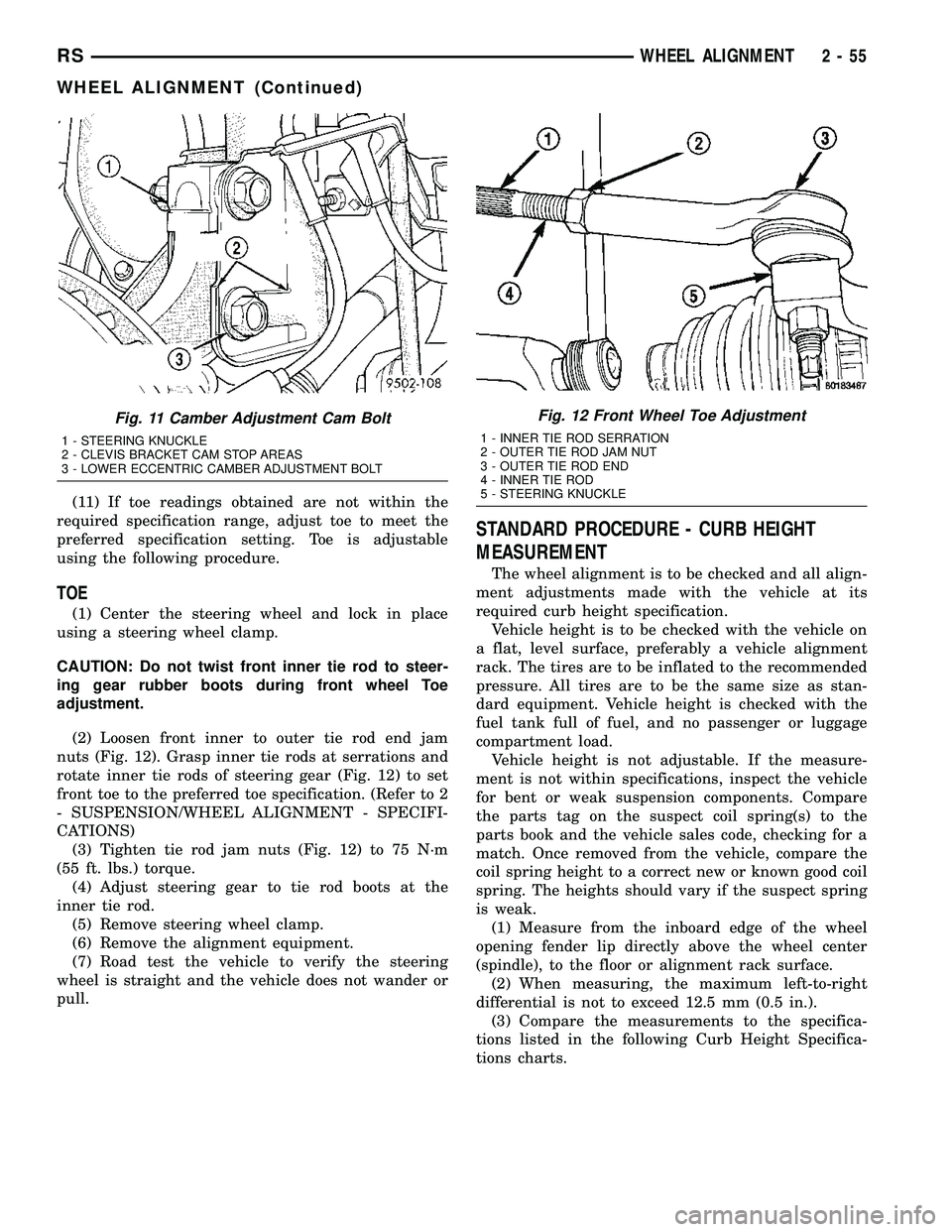
nuts (Fig. 12). Grasp inner tie rods at serrations and
rotate inner tie rods of steering gear (Fig. 12) to set
front toe to the preferred toe specification. (Refer to 2
- SUSPENSION/WHEEL ALIGNMENT - SPECIFI-
CATIONS)
(3) Tighten tie rod jam nuts (Fig. 12) to 75 N´m
(55 ft. lbs.) torque.
(4) Adjust steering gear to tie rod boots at the
inner tie rod.
(5) Remove steering wheel clamp.
(6) Remove the alignment equipment.
(7) Road test the vehicle to verify the steering
wheel is straight and the vehicle does not wander or
pull.
STANDARD PROCEDURE - CURB HEIGHT
MEASUREMENT
The wheel alignment is to be checked and all align-
ment adjustments made with the vehicle at its
required curb height specification.
Vehicle height is to be checked with the vehicle on
a flat, level surface, preferably a vehicle alignment
rack. The tires are to be inflated to the recommended
pressure. All tires are to be the same size as stan-
dard equipment. Vehicle height is checked with the
fuel tank full of fuel, and no passenger or luggage
compartment load.
Vehicle height is not adjustable. If the measure-
ment is not within specifications, inspect the vehicle
for bent or weak suspension components. Compare
the parts tag on the suspect coil spring(s) to the
parts book and the vehicle sales code, checking for a
match. Once removed from the vehicle, compare the
coil spring height to a correct new or known good coil
spring. The heights should vary if the suspect spring
is weak.
(1) Measure from the inboard edge of the wheel
opening fender lip directly above the wheel center
(spindle), to the floor or alignment rack surface.
(2) When measuring, the maximum left-to-right
differential is not to exceed 12.5 mm (0.5 in.).
(3) Compare the measurements to the specifica-
tions listed in the following Curb Height Specifica-
tions charts.
Fig. 11 Camber Adjustment Cam Bolt
1 - STEERING KNUCKLE
2 - CLEVIS BRACKET CAM STOP AREAS
3 - LOWER ECCENTRIC CAMBER ADJUSTMENT BOLT
Fig. 12 Front Wheel Toe Adjustment
1 - INNER TIE ROD SERRATION
2 - OUTER TIE ROD JAM NUT
3 - OUTER TIE ROD END
4 - INNER TIE ROD
5 - STEERING KNUCKLE
RSWHEEL ALIGNMENT2-55
WHEEL ALIGNMENT (Continued)
Page 98 of 2339
DIFFERENTIAL & DRIVELINE
HALF SHAFT - FRONT
TABLE OF CONTENTS
page page
HALF SHAFT - FRONT
DESCRIPTION..........................1
DIAGNOSIS AND TESTING - HALF SHAFT.....1
REMOVAL.............................2
INSTALLATION..........................4
SPECIFICATIONS - HALF SHAFT - FRONT....6CV BOOT - INNER
REMOVAL.............................6
INSTALLATION..........................7
CV BOOT - OUTER
REMOVAL.............................10
INSTALLATION.........................11
HALF SHAFT - FRONT
DESCRIPTION
All vehicles use an unequal length half shaft sys-
tem (Fig. 1).
The left half shaft uses a tuned rubber damper
weight. When replacing the left half shaft, be sure
the replacement half shaft has the same damper
weight as the original.
All half shaft assemblies use the same type of
inner and outer joints. The inner joint of both half
shaft assemblies is a tripod joint, and the outer joint
of both half shaft assemblies is a Rzeppa joint. Both
tripod joints and Rzeppa joints are true constant
velocity (CV) joint assemblies. The inner tripod joint
allows for the changes in half shaft length through
the jounce and rebound travel of the front suspen-
sion.
On vehicles equipped with ABS brakes, the outer
CV joint is equipped with a tone wheel used to deter-
mine vehicle speed for ABS brake operation.
The inner tripod joint of both half shafts is splined
into the transaxle side gears. The inner tripod joints
are retained in the side gears of the transaxle using
a snap ring located in the stub shaft of the tripod
joint. The outer CV joint has a stub shaft that is
splined into the wheel hub and retained by a steel
hub nut.
DIAGNOSIS AND TESTING - HALF SHAFT
VEHICLE INSPECTION
(1) Check for grease in the vicinity of the inboard
tripod joint and outboard CV joint; this is a sign of
inner or outer joint seal boot or seal boot clamp dam-
age.
NOISE AND/OR VIBRATION IN TURNS
A clicking noise and/or a vibration in turns could
be caused by one of the following conditions:
²Damaged outer CV or inner tripod joint seal
boot or seal boot clamps. This will result in the loss
and/or contamination of the joint grease, resulting in
inadequate lubrication of the joint.
²Noise may also be caused by another component
of the vehicle coming in contact with the half shafts.
CLUNKING NOISE DURING ACCELERATION
This noise may be a result of one of the following
conditions:
²A torn seal boot on the inner or outer joint of the
half shaft assembly.
²A loose or missing clamp on the inner or outer
joint of the half shaft assembly.
²A damaged or worn half shaft CV joint.
SHUDDER OR VIBRATION DURING ACCELERATION
This problem could be a result of:
²A worn or damaged half shaft inner tripod joint.
RSDIFFERENTIAL & DRIVELINE3-1
Page 103 of 2339
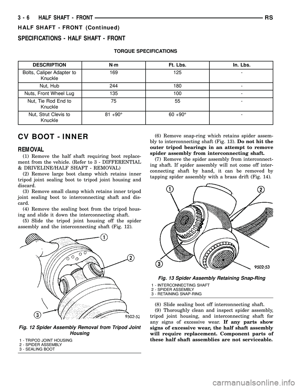
SPECIFICATIONS - HALF SHAFT - FRONT
TORQUE SPECIFICATIONS
DESCRIPTION N´m Ft. Lbs. In. Lbs.
Bolts, Caliper Adapter to
Knuckle169 125 -
Nut, Hub 244 180 -
Nuts, Front Wheel Lug 135 100 -
Nut, Tie Rod End to
Knuckle75 55 -
Nut, Strut Clevis to
Knuckle81 +90É 60 +90É -
CV BOOT - INNER
REMOVAL
(1) Remove the half shaft requiring boot replace-
ment from the vehicle. (Refer to 3 - DIFFERENTIAL
& DRIVELINE/HALF SHAFT - REMOVAL)
(2) Remove large boot clamp which retains inner
tripod joint sealing boot to tripod joint housing and
discard.
(3) Remove small clamp which retains inner tripod
joint sealing boot to interconnecting shaft and dis-
card.
(4) Remove the sealing boot from the tripod hous-
ing and slide it down the interconnecting shaft.
(5) Slide the tripod joint housing off the spider
assembly and the interconnecting shaft (Fig. 12).(6) Remove snap-ring which retains spider assem-
bly to interconnecting shaft (Fig. 13).Do not hit the
outer tripod bearings in an attempt to remove
spider assembly from interconnecting shaft.
(7) Remove the spider assembly from interconnect-
ing shaft. If spider assembly will not come off inter-
connecting shaft by hand, it can be removed by
tapping spider assembly with a brass drift (Fig. 14).
(8) Slide sealing boot off interconnecting shaft.
(9) Thoroughly clean and inspect spider assembly,
tripod joint housing, and interconnecting shaft for
any signs of excessive wear.If any parts show
signs of excessive wear, the half shaft assembly
will require replacement. Component parts of
these half shaft assemblies are not serviceable.
Fig. 12 Spider Assembly Removal from Tripod Joint
Housing
1 - TRIPOD JOINT HOUSING
2 - SPIDER ASSEMBLY
3 - SEALING BOOT
Fig. 13 Spider Assembly Retaining Snap-Ring
1 - INTERCONNECTING SHAFT
2 - SPIDER ASSEMBLY
3 - RETAINING SNAP-RING
3 - 6 HALF SHAFT - FRONTRS
HALF SHAFT - FRONT (Continued)
Page 107 of 2339
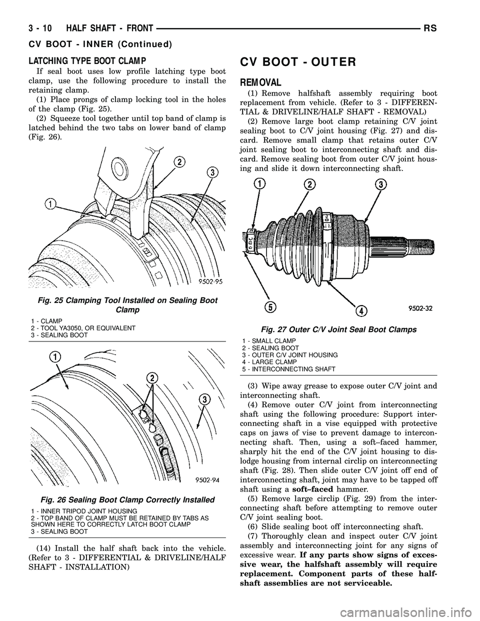
LATCHING TYPE BOOT CLAMP
If seal boot uses low profile latching type boot
clamp, use the following procedure to install the
retaining clamp.
(1) Place prongs of clamp locking tool in the holes
of the clamp (Fig. 25).
(2) Squeeze tool together until top band of clamp is
latched behind the two tabs on lower band of clamp
(Fig. 26).
(14) Install the half shaft back into the vehicle.
(Refer to 3 - DIFFERENTIAL & DRIVELINE/HALF
SHAFT - INSTALLATION)
CV BOOT - OUTER
REMOVAL
(1) Remove halfshaft assembly requiring boot
replacement from vehicle. (Refer to 3 - DIFFEREN-
TIAL & DRIVELINE/HALF SHAFT - REMOVAL)
(2) Remove large boot clamp retaining C/V joint
sealing boot to C/V joint housing (Fig. 27) and dis-
card. Remove small clamp that retains outer C/V
joint sealing boot to interconnecting shaft and dis-
card. Remove sealing boot from outer C/V joint hous-
ing and slide it down interconnecting shaft.
(3) Wipe away grease to expose outer C/V joint and
interconnecting shaft.
(4) Remove outer C/V joint from interconnecting
shaft using the following procedure: Support inter-
connecting shaft in a vise equipped with protective
caps on jaws of vise to prevent damage to intercon-
necting shaft. Then, using a soft±faced hammer,
sharply hit the end of the C/V joint housing to dis-
lodge housing from internal circlip on interconnecting
shaft (Fig. 28). Then slide outer C/V joint off end of
interconnecting shaft, joint may have to be tapped off
shaft using asoft±facedhammer.
(5) Remove large circlip (Fig. 29) from the inter-
connecting shaft before attempting to remove outer
C/V joint sealing boot.
(6) Slide sealing boot off interconnecting shaft.
(7) Thoroughly clean and inspect outer C/V joint
assembly and interconnecting joint for any signs of
excessive wear.If any parts show signs of exces-
sive wear, the halfshaft assembly will require
replacement. Component parts of these half-
shaft assemblies are not serviceable.
Fig. 25 Clamping Tool Installed on Sealing Boot
Clamp
1 - CLAMP
2 - TOOL YA3050, OR EQUIVALENT
3 - SEALING BOOT
Fig. 26 Sealing Boot Clamp Correctly Installed
1 - INNER TRIPOD JOINT HOUSING
2 - TOP BAND OF CLAMP MUST BE RETAINED BY TABS AS
SHOWN HERE TO CORRECTLY LATCH BOOT CLAMP
3 - SEALING BOOT
Fig. 27 Outer C/V Joint Seal Boot Clamps
1 - SMALL CLAMP
2 - SEALING BOOT
3 - OUTER C/V JOINT HOUSING
4 - LARGE CLAMP
5 - INTERCONNECTING SHAFT
3 - 10 HALF SHAFT - FRONTRS
CV BOOT - INNER (Continued)
Page 205 of 2339
(1) Lubricate the sensor O-ring with Mopar Wheel
Bearing Grease before installation into the Hub And
Bearing.If not lubricated, an improper seal may
result due to rolling of the O-ring.
(2) If metal sensor retaining clip is not in the neu-
tral installed position on hub and bearing cap, install
from the bottom, if necessary, and push clip upward
until it snaps into position.
(3) Install wheel speed sensor head into rear of
hub and bearing aligning index tab with the notch in
the top of the mounting hole. Push the sensor in
until it snaps into place on the metal retaining clip.
(4)
Install secondary (yellow) retaining clip over wheel
speed sensor head and engage the tabs on each side.
(5) Route sensor cable under leaf spring along rear
of axle. Install speed sensor cable into routing clips
on rear brake flex hose (Fig. 3).
(6) Install cable into metal routing clip and attach
it to the rear axle with mounting bolt (Fig. 3).
Tighten mounting bolt to 16 N´m (140 in. lbs.).
(7) Connect wheel speed sensor cable to vehicle
wiring harness (Fig. 2).Be sure speed sensor
cable connector is fully seated and locked into
vehicle wiring harness connector.
(8)
Install speed sensor cable grommet into hole in
floor pan making sure grommet is fully seated into hole.
(9) Lower vehicle.
(10) Road test vehicle to ensure proper operation
of the base and ABS braking systems.
TONE WHEEL
INSPECTION - TONE WHEEL
NOTE: Rear tone wheels for front-wheel-drive vehi-
cles are sealed within the hub and bearing assem-
bly and cannot be inspected or replaced.
Replacement of the hub and bearing is necessary.
Tone wheels can cause erratic wheel speed sensor
signals. Inspect tone wheels for the following possible
causes.
²missing, chipped, or broken teeth
²contact with the wheel speed sensor
²wheel speed sensor to tone wheel alignment
²wheel speed sensor to tone wheel clearance
²excessive tone wheel runout
²tone wheel loose on its mounting surface
If a front tone wheel is found to need replacement,
the drive shaft must be replaced. No attempt should
be made to replace just the tone wheel. (Refer to 3 -
DIFFERENTIAL & DRIVELINE/HALF SHAFT -
REMOVAL)
If a rear tone wheel is found to need replacement
on an all-wheel-drive model, the drive shaft must be
replaced. No attempt should be made to replace justthe tone wheel. (Refer to 3 - DIFFERENTIAL &
DRIVELINE/HALF SHAFT - REMOVAL)
If wheel speed sensor to tone wheel contact is evi-
dent, determine the cause and correct it before
replacing the wheel speed sensor or tone wheel.
Check the gap between the speed sensor head and
the tone wheel to ensure it is within specifications.
(Refer to 5 - BRAKES - ABS/ELECTRICAL - SPEC-
IFICATIONS)
Excessive wheel speed sensor runout can cause
erratic wheel speed sensor signals. Refer to SPECI-
FICATIONS in this section of the service manual for
the maximum allowed tone wheel runout (Refer to 5 -
BRAKES - ABS/ELECTRICAL - SPECIFICATIONS).
If tone wheel runout is excessive, determine if it is
caused by a defect in the driveshaft assembly or hub
and bearing. Replace as necessary.
Tone wheels are pressed onto their mounting sur-
faces and should not rotate independently from the
mounting surface. Replacement of the front drive-
shaft, rear driveshaft (AWD only) or rear hub and
bearing is necessary.
TRACTION CONTROL SWITCH
DIAGNOSIS AND TESTING - TRACTION
CONTROL SWITCH
(1) Remove lower steering column shroud. (Refer
to 19 - STEERING/COLUMN/LOWER SHROUD -
REMOVAL)
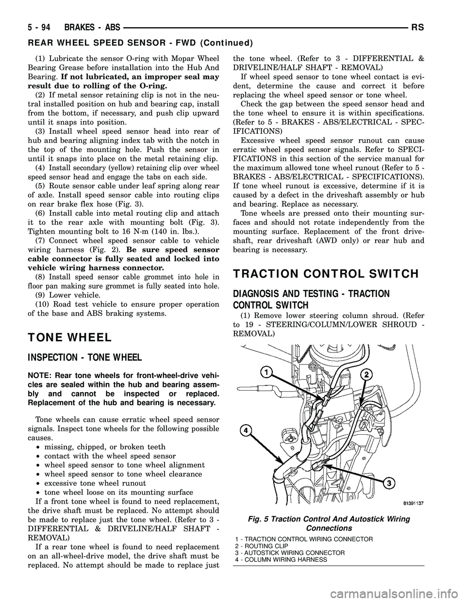
Fig. 5 Traction Control And Autostick Wiring
Connections
1 - TRACTION CONTROL WIRING CONNECTOR
2 - ROUTING CLIP
3 - AUTOSTICK WIRING CONNECTOR
4 - COLUMN WIRING HARNESS
5 - 94 BRAKES - ABSRS
REAR WHEEL SPEED SENSOR - FWD (Continued)
Page 1345 of 2339
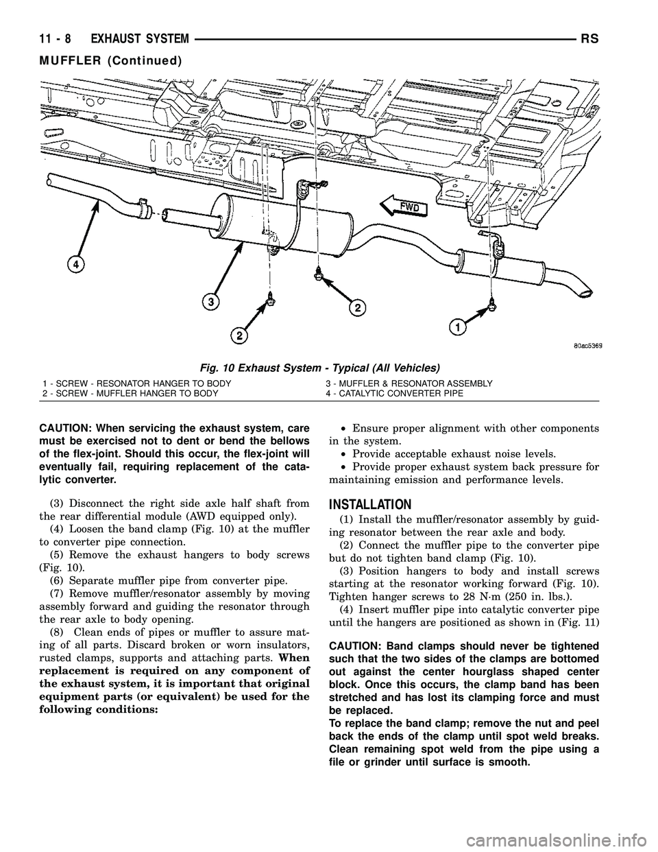
CAUTION: When servicing the exhaust system, care
must be exercised not to dent or bend the bellows
of the flex-joint. Should this occur, the flex-joint will
eventually fail, requiring replacement of the cata-
lytic converter.
(3) Disconnect the right side axle half shaft from
the rear differential module (AWD equipped only).
(4) Loosen the band clamp (Fig. 10) at the muffler
to converter pipe connection.
(5) Remove the exhaust hangers to body screws
(Fig. 10).
(6) Separate muffler pipe from converter pipe.
(7) Remove muffler/resonator assembly by moving
assembly forward and guiding the resonator through
the rear axle to body opening.
(8) Clean ends of pipes or muffler to assure mat-
ing of all parts. Discard broken or worn insulators,
rusted clamps, supports and attaching parts.When
replacement is required on any component of
the exhaust system, it is important that original
equipment parts (or equivalent) be used for the
following conditions:²Ensure proper alignment with other components
in the system.
²Provide acceptable exhaust noise levels.
²Provide proper exhaust system back pressure for
maintaining emission and performance levels.
INSTALLATION
(1) Install the muffler/resonator assembly by guid-
ing resonator between the rear axle and body.
(2) Connect the muffler pipe to the converter pipe
but do not tighten band clamp (Fig. 10).
(3) Position hangers to body and install screws
starting at the resonator working forward (Fig. 10).
Tighten hanger screws to 28 N´m (250 in. lbs.).
(4) Insert muffler pipe into catalytic converter pipe
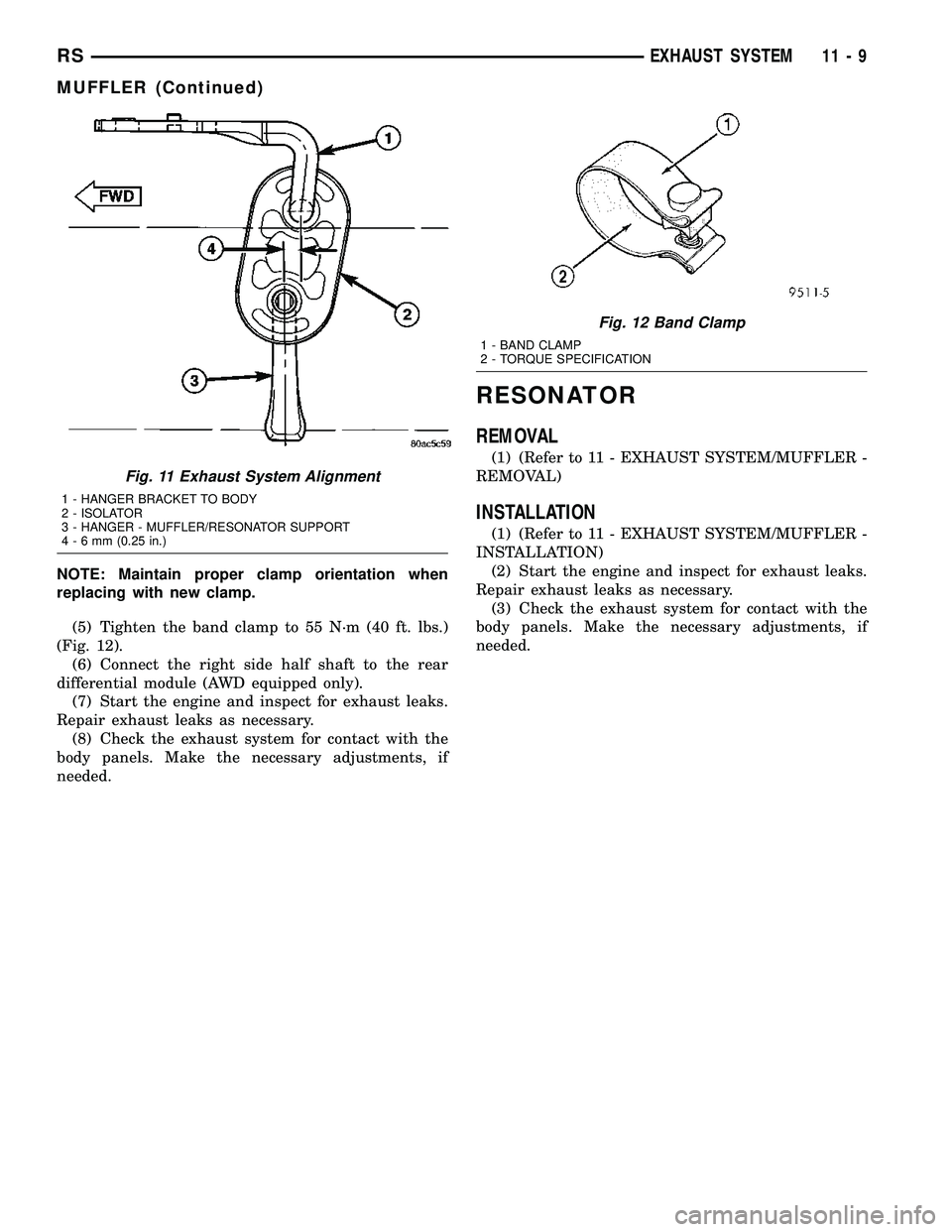
until the hangers are positioned as shown in (Fig. 11)
CAUTION: Band clamps should never be tightened
such that the two sides of the clamps are bottomed
out against the center hourglass shaped center
block. Once this occurs, the clamp band has been
stretched and has lost its clamping force and must
be replaced.
To replace the band clamp; remove the nut and peel
back the ends of the clamp until spot weld breaks.
Clean remaining spot weld from the pipe using a
file or grinder until surface is smooth.
Fig. 10 Exhaust System - Typical (All Vehicles)
1 - SCREW - RESONATOR HANGER TO BODY 3 - MUFFLER & RESONATOR ASSEMBLY
2 - SCREW - MUFFLER HANGER TO BODY 4 - CATALYTIC CONVERTER PIPE
11 - 8 EXHAUST SYSTEMRS
MUFFLER (Continued)
Page 1346 of 2339
NOTE: Maintain proper clamp orientation when
replacing with new clamp.
(5) Tighten the band clamp to 55 N´m (40 ft. lbs.)
(Fig. 12).
(6) Connect the right side half shaft to the rear
differential module (AWD equipped only).
(7) Start the engine and inspect for exhaust leaks.
Repair exhaust leaks as necessary.
(8) Check the exhaust system for contact with the
body panels. Make the necessary adjustments, if
needed.
RESONATOR
REMOVAL
(1) (Refer to 11 - EXHAUST SYSTEM/MUFFLER -
REMOVAL)
INSTALLATION
(1) (Refer to 11 - EXHAUST SYSTEM/MUFFLER -
INSTALLATION)
(2) Start the engine and inspect for exhaust leaks.
Repair exhaust leaks as necessary.
(3) Check the exhaust system for contact with the
body panels. Make the necessary adjustments, if
needed.
Fig. 11 Exhaust System Alignment
1 - HANGER BRACKET TO BODY
2 - ISOLATOR
3 - HANGER - MUFFLER/RESONATOR SUPPORT
4-6mm(0.25 in.)
Fig. 12 Band Clamp
1 - BAND CLAMP
2 - TORQUE SPECIFICATION
RSEXHAUST SYSTEM11-9
MUFFLER (Continued)