index CHRYSLER CARAVAN 2005 Service Manual
[x] Cancel search | Manufacturer: CHRYSLER, Model Year: 2005, Model line: CARAVAN, Model: CHRYSLER CARAVAN 2005Pages: 2339, PDF Size: 59.69 MB
Page 1 of 2339
GROUP TAB LOCATOR
Introduction
0Lubrication & Maintenance
2Suspension
3Differential & Driveline
5Brakes
7Cooling
8AAudio
8BChime/Buzzer
8EElectronic Control Modules
8FEngine Systems
8GHeated Systems
8HHorn
8IIgnition Control
8JInstrument Cluster
8LLamps
8MMessage Systems
8NPower Systems
8ORestraints
8PSpeed Control
8QVehicle Theft Security
8RWipers/Washers
8TNavigation/Telecommunication
8WWiring
9Engine
11Exhaust System
13Frame & Bumpers
14Fuel System
19Steering
21Transmission/Transaxle
22Tires/Wheels
23Body
24Heating & Air Conditioning
25Emissions Control
Component and System Index
Service Manual Comment Forms (Rear of Manual)
Page 74 of 2339
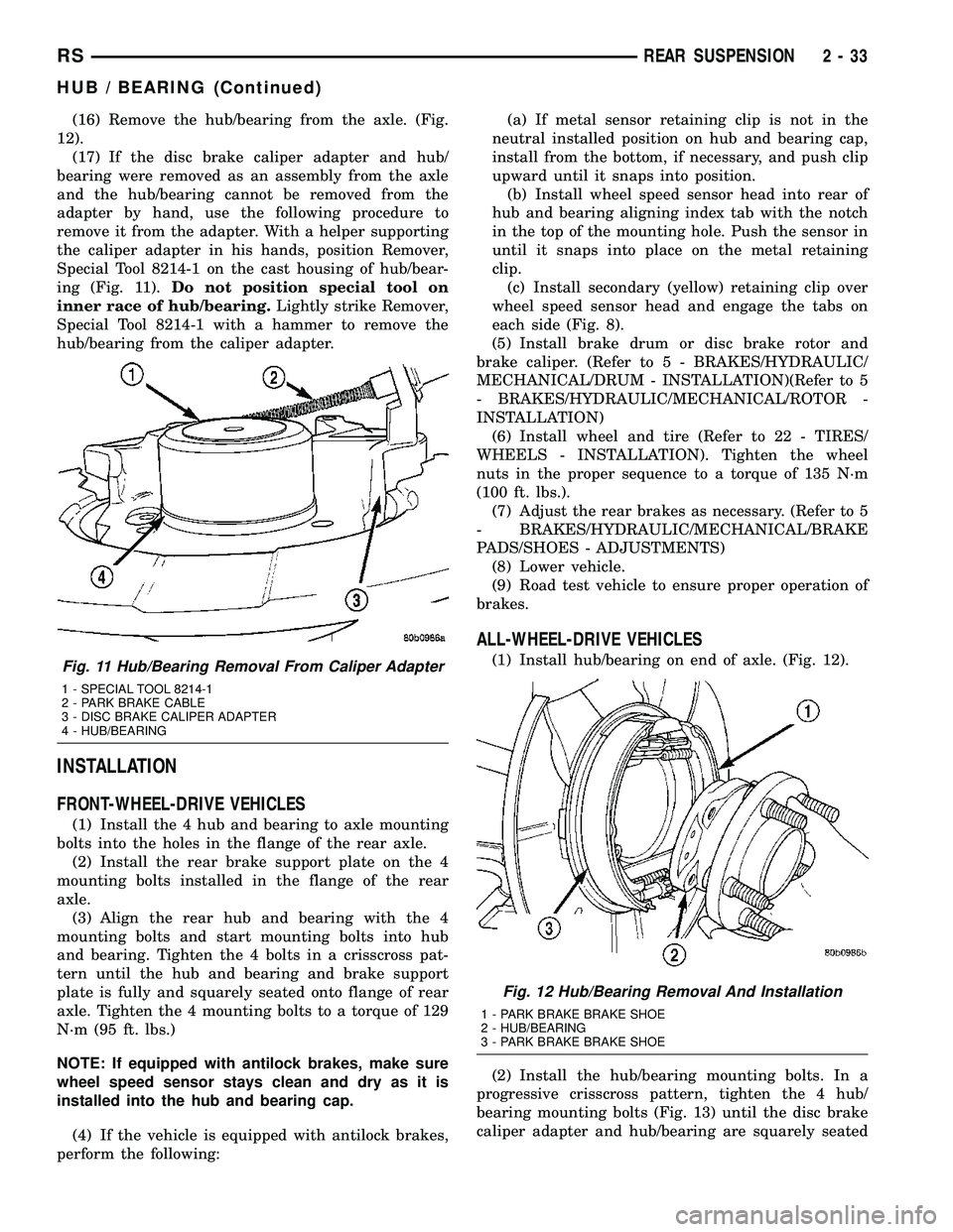
(16) Remove the hub/bearing from the axle. (Fig.
12).
(17) If the disc brake caliper adapter and hub/
bearing were removed as an assembly from the axle
and the hub/bearing cannot be removed from the
adapter by hand, use the following procedure to
remove it from the adapter. With a helper supporting
the caliper adapter in his hands, position Remover,
Special Tool 8214-1 on the cast housing of hub/bear-
ing (Fig. 11).Do not position special tool on
inner race of hub/bearing.Lightly strike Remover,
Special Tool 8214-1 with a hammer to remove the
hub/bearing from the caliper adapter.
INSTALLATION
FRONT-WHEEL-DRIVE VEHICLES
(1) Install the 4 hub and bearing to axle mounting
bolts into the holes in the flange of the rear axle.
(2) Install the rear brake support plate on the 4
mounting bolts installed in the flange of the rear
axle.
(3) Align the rear hub and bearing with the 4
mounting bolts and start mounting bolts into hub
and bearing. Tighten the 4 bolts in a crisscross pat-
tern until the hub and bearing and brake support
plate is fully and squarely seated onto flange of rear
axle. Tighten the 4 mounting bolts to a torque of 129
N´m (95 ft. lbs.)
NOTE: If equipped with antilock brakes, make sure
wheel speed sensor stays clean and dry as it is
installed into the hub and bearing cap.
(4) If the vehicle is equipped with antilock brakes,
perform the following:(a) If metal sensor retaining clip is not in the
neutral installed position on hub and bearing cap,
install from the bottom, if necessary, and push clip
upward until it snaps into position.
(b) Install wheel speed sensor head into rear of
hub and bearing aligning index tab with the notch
in the top of the mounting hole. Push the sensor in
until it snaps into place on the metal retaining
clip.
(c) Install secondary (yellow) retaining clip over
wheel speed sensor head and engage the tabs on
each side (Fig. 8).
(5) Install brake drum or disc brake rotor and
brake caliper. (Refer to 5 - BRAKES/HYDRAULIC/
MECHANICAL/DRUM - INSTALLATION)(Refer to 5
- BRAKES/HYDRAULIC/MECHANICAL/ROTOR -
INSTALLATION)
(6) Install wheel and tire (Refer to 22 - TIRES/
WHEELS - INSTALLATION). Tighten the wheel
nuts in the proper sequence to a torque of 135 N´m
(100 ft. lbs.).
(7) Adjust the rear brakes as necessary. (Refer to 5
- BRAKES/HYDRAULIC/MECHANICAL/BRAKE
PADS/SHOES - ADJUSTMENTS)
(8) Lower vehicle.
(9) Road test vehicle to ensure proper operation of
brakes.
ALL-WHEEL-DRIVE VEHICLES
(1) Install hub/bearing on end of axle. (Fig. 12).
(2) Install the hub/bearing mounting bolts. In a
progressive crisscross pattern, tighten the 4 hub/
bearing mounting bolts (Fig. 13) until the disc brake
caliper adapter and hub/bearing are squarely seatedFig. 11 Hub/Bearing Removal From Caliper Adapter
1 - SPECIAL TOOL 8214-1
2 - PARK BRAKE CABLE
3 - DISC BRAKE CALIPER ADAPTER
4 - HUB/BEARING
Fig. 12 Hub/Bearing Removal And Installation
1 - PARK BRAKE BRAKE SHOE
2 - HUB/BEARING
3 - PARK BRAKE BRAKE SHOE
RSREAR SUSPENSION2-33
HUB / BEARING (Continued)
Page 168 of 2339
ROTOR RUNOUT
On-vehicle rotor runout is the combination of the
individual runout of the hub face and the runout of
the rotor. (The hub and rotor runouts are separable).
To measure rotor runout on the vehicle, first remove
the tire and wheel assembly. Reinstall the wheel
mounting nuts on the studs, tightening the rotor to
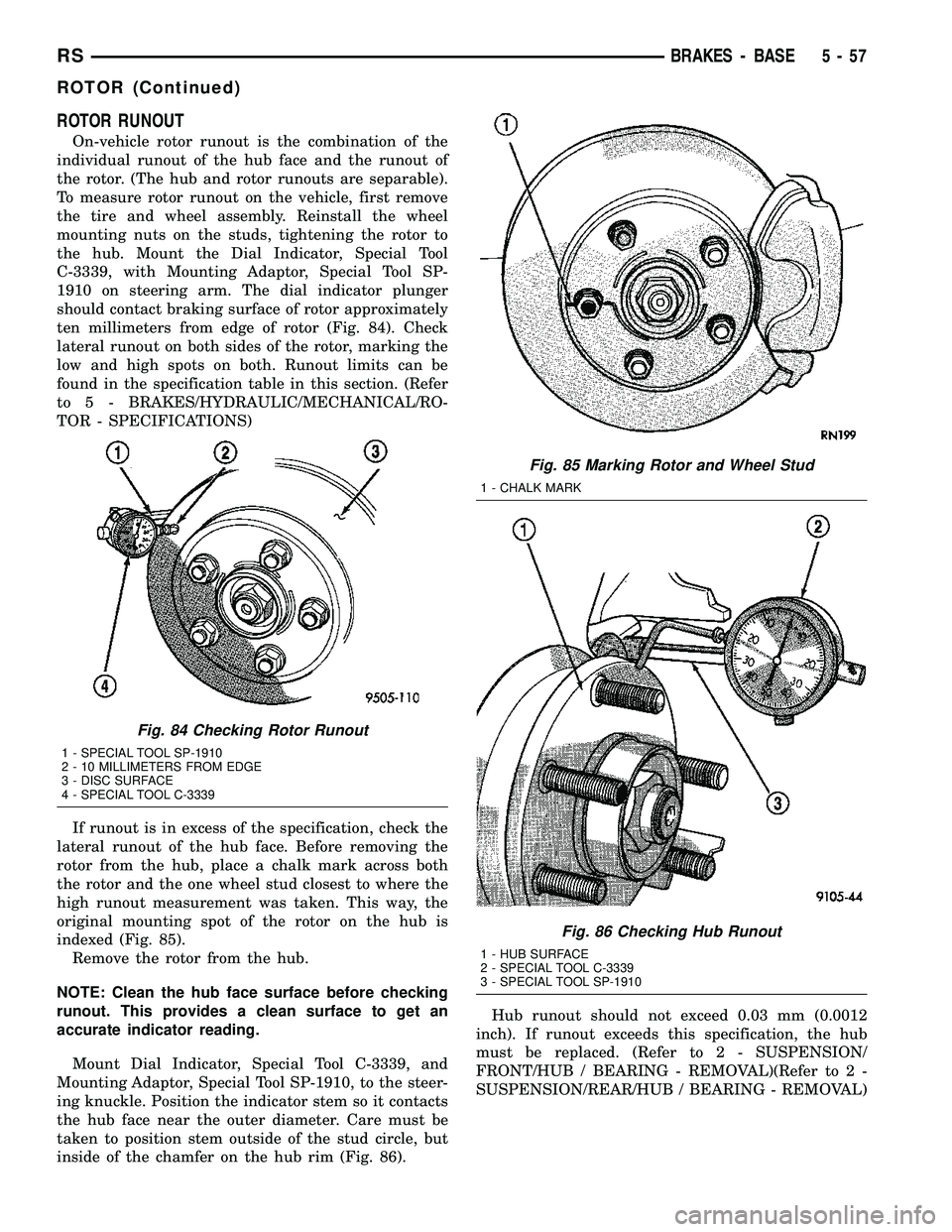
the hub. Mount the Dial Indicator, Special Tool
C-3339, with Mounting Adaptor, Special Tool SP-
1910 on steering arm. The dial indicator plunger
should contact braking surface of rotor approximately
ten millimeters from edge of rotor (Fig. 84). Check
lateral runout on both sides of the rotor, marking the
low and high spots on both. Runout limits can be
found in the specification table in this section. (Refer
to 5 - BRAKES/HYDRAULIC/MECHANICAL/RO-
TOR - SPECIFICATIONS)
If runout is in excess of the specification, check the
lateral runout of the hub face. Before removing the
rotor from the hub, place a chalk mark across both
the rotor and the one wheel stud closest to where the
high runout measurement was taken. This way, the
original mounting spot of the rotor on the hub is
indexed (Fig. 85).
Remove the rotor from the hub.
NOTE: Clean the hub face surface before checking
runout. This provides a clean surface to get an
accurate indicator reading.
Mount Dial Indicator, Special Tool C-3339, and
Mounting Adaptor, Special Tool SP-1910, to the steer-
ing knuckle. Position the indicator stem so it contacts
the hub face near the outer diameter. Care must be
taken to position stem outside of the stud circle, but
inside of the chamfer on the hub rim (Fig. 86).Hub runout should not exceed 0.03 mm (0.0012
inch). If runout exceeds this specification, the hub
must be replaced. (Refer to 2 - SUSPENSION/
FRONT/HUB / BEARING - REMOVAL)(Refer to 2 -
SUSPENSION/REAR/HUB / BEARING - REMOVAL)
Fig. 84 Checking Rotor Runout
1 - SPECIAL TOOL SP-1910
2 - 10 MILLIMETERS FROM EDGE
3 - DISC SURFACE
4 - SPECIAL TOOL C-3339
Fig. 85 Marking Rotor and Wheel Stud
1 - CHALK MARK
Fig. 86 Checking Hub Runout
1 - HUB SURFACE
2 - SPECIAL TOOL C-3339
3 - SPECIAL TOOL SP-1910
RSBRAKES - BASE5-57
ROTOR (Continued)
Page 169 of 2339
If the hub runout does not exceed this specifica-
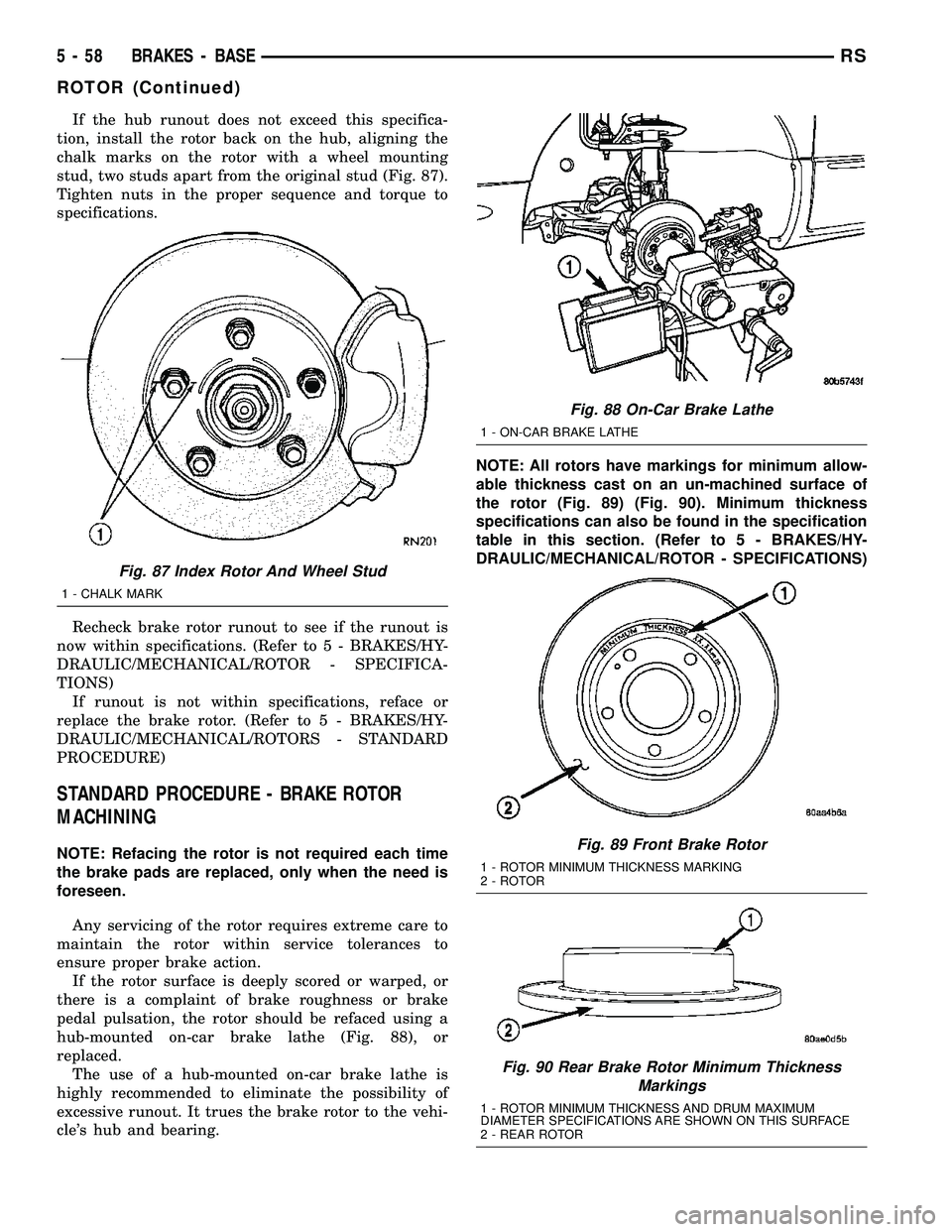
tion, install the rotor back on the hub, aligning the
chalk marks on the rotor with a wheel mounting
stud, two studs apart from the original stud (Fig. 87).
Tighten nuts in the proper sequence and torque to
specifications.
Recheck brake rotor runout to see if the runout is
now within specifications. (Refer to 5 - BRAKES/HY-
DRAULIC/MECHANICAL/ROTOR - SPECIFICA-
TIONS)
If runout is not within specifications, reface or
replace the brake rotor. (Refer to 5 - BRAKES/HY-
DRAULIC/MECHANICAL/ROTORS - STANDARD
PROCEDURE)
STANDARD PROCEDURE - BRAKE ROTOR
MACHINING
NOTE: Refacing the rotor is not required each time
the brake pads are replaced, only when the need is
foreseen.
Any servicing of the rotor requires extreme care to
maintain the rotor within service tolerances to
ensure proper brake action.
If the rotor surface is deeply scored or warped, or
there is a complaint of brake roughness or brake
pedal pulsation, the rotor should be refaced using a
hub-mounted on-car brake lathe (Fig. 88), or
replaced.
The use of a hub-mounted on-car brake lathe is
highly recommended to eliminate the possibility of
excessive runout. It trues the brake rotor to the vehi-
cle's hub and bearing.NOTE: All rotors have markings for minimum allow-
able thickness cast on an un-machined surface of
the rotor (Fig. 89) (Fig. 90). Minimum thickness
specifications can also be found in the specification
table in this section. (Refer to 5 - BRAKES/HY-
DRAULIC/MECHANICAL/ROTOR - SPECIFICATIONS)
Fig. 87 Index Rotor And Wheel Stud
1 - CHALK MARK
Fig. 88 On-Car Brake Lathe
1 - ON-CAR BRAKE LATHE
Fig. 89 Front Brake Rotor
1 - ROTOR MINIMUM THICKNESS MARKING
2 - ROTOR
Fig. 90 Rear Brake Rotor Minimum Thickness
Markings
1 - ROTOR MINIMUM THICKNESS AND DRUM MAXIMUM
DIAMETER SPECIFICATIONS ARE SHOWN ON THIS SURFACE
2 - REAR ROTOR
5 - 58 BRAKES - BASERS
ROTOR (Continued)
Page 195 of 2339
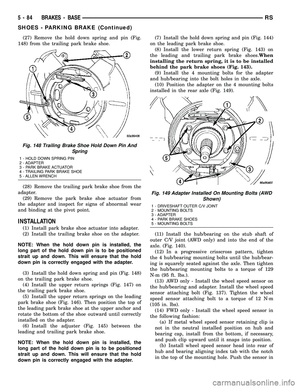
(27) Remove the hold down spring and pin (Fig.
148) from the trailing park brake shoe.
(28) Remove the trailing park brake shoe from the
adapter.
(29) Remove the park brake shoe actuator from
the adapter and inspect for signs of abnormal wear
and binding at the pivot point.
INSTALLATION
(1) Install park brake shoe actuator into adapter.
(2) Install the trailing brake shoe on the adapter.
NOTE: When the hold down pin is installed, the
long part of the hold down pin is to be positioned
strait up and down. This will ensure that the hold
down pin is correctly engaged with the adapter.
(3) Install the hold down spring and pin (Fig. 148)
on the trailing park brake shoe.
(4) Install the upper return springs (Fig. 147) on
the trailing park brake shoe.
(5) Install the upper return springs on the leading
park brake shoe (Fig. 146). Then position the top of
the leading park brake shoe at the upper anchor and
rotate the bottom of the shoe outward until correctly
installed on the adapter.
(6) Install the adjuster (Fig. 145) between the
leading and trailing park brake shoe.
NOTE: When the hold down pin is installed, the
long part of the hold down pin is to be positioned
strait up and down. This will ensure that the hold
down pin is correctly engaged with the adapter.(7) Install the hold down spring and pin (Fig. 144)
on the leading park brake shoe.
(8) Install the lower return spring (Fig. 143) on
the leading and trailing park brake shoes.When
installing the return spring, it is to be installed
behind the park brake shoes (Fig. 143).
(9) Install the 4 mounting bolts for the adapter
and hub/bearing into the bolt holes in the axle.
(10) Position the adapter on the 4 mounting bolts
installed in the rear axle (Fig. 149).
(11) Install the hub/bearing on the stub shaft of
outer C/V joint (AWD only) and into the end of the
axle. (Fig. 140).
(12) In a progressive crisscross pattern, tighten
the 4 hub/bearing mounting bolts until the hub/bear-
ing is squarely seated against the axle. Then tighten
the hub/bearing mounting bolts to a torque of 129
N´m (95 ft. lbs.).
(13) AWD only - Install the wheel speed sensor on
the hub/bearing and adapter. Install the wheel speed
sensor attaching bolt (Fig. 137). Tighten the wheel
speed sensor attaching bolt to a torque of 12 N´m
(105 in. lbs).
(14) FWD only - Install the wheel speed sensor in
the following fashion:
(a) If metal wheel speed sensor retaining clip is
not in the neutral installed position on hub and
bearing cap, install from the bottom, if necessary,
and push clip upward until it snaps into position.
(b) Install wheel speed sensor head into rear of
hub and bearing aligning index tab with the notch
in the top of the mounting hole. Push the sensor in
Fig. 148 Trailing Brake Shoe Hold Down Pin And
Spring
1 - HOLD DOWN SPRING PIN
2 - ADAPTER
3 - PARK BRAKE ACTUATOR
4 - TRAILING PARK BRAKE SHOE
5 - ALLEN WRENCH
Fig. 149 Adapter Installed On Mounting Bolts (AWD
Shown)
1 - DRIVESHAFT OUTER C/V JOINT
2 - MOUNTING BOLTS
3 - ADAPTER
4 - PARK BRAKE SHOES
5 - MOUNTING BOLTS
5 - 84 BRAKES - BASERS
SHOES - PARKING BRAKE (Continued)
Page 205 of 2339
(1) Lubricate the sensor O-ring with Mopar Wheel
Bearing Grease before installation into the Hub And
Bearing.If not lubricated, an improper seal may
result due to rolling of the O-ring.
(2) If metal sensor retaining clip is not in the neu-
tral installed position on hub and bearing cap, install
from the bottom, if necessary, and push clip upward
until it snaps into position.
(3) Install wheel speed sensor head into rear of
hub and bearing aligning index tab with the notch in
the top of the mounting hole. Push the sensor in
until it snaps into place on the metal retaining clip.
(4)
Install secondary (yellow) retaining clip over wheel
speed sensor head and engage the tabs on each side.
(5) Route sensor cable under leaf spring along rear
of axle. Install speed sensor cable into routing clips
on rear brake flex hose (Fig. 3).
(6) Install cable into metal routing clip and attach
it to the rear axle with mounting bolt (Fig. 3).
Tighten mounting bolt to 16 N´m (140 in. lbs.).
(7) Connect wheel speed sensor cable to vehicle
wiring harness (Fig. 2).Be sure speed sensor
cable connector is fully seated and locked into
vehicle wiring harness connector.
(8)
Install speed sensor cable grommet into hole in
floor pan making sure grommet is fully seated into hole.
(9) Lower vehicle.
(10) Road test vehicle to ensure proper operation
of the base and ABS braking systems.
TONE WHEEL
INSPECTION - TONE WHEEL
NOTE: Rear tone wheels for front-wheel-drive vehi-
cles are sealed within the hub and bearing assem-
bly and cannot be inspected or replaced.
Replacement of the hub and bearing is necessary.
Tone wheels can cause erratic wheel speed sensor
signals. Inspect tone wheels for the following possible
causes.
²missing, chipped, or broken teeth
²contact with the wheel speed sensor
²wheel speed sensor to tone wheel alignment
²wheel speed sensor to tone wheel clearance
²excessive tone wheel runout
²tone wheel loose on its mounting surface
If a front tone wheel is found to need replacement,
the drive shaft must be replaced. No attempt should
be made to replace just the tone wheel. (Refer to 3 -
DIFFERENTIAL & DRIVELINE/HALF SHAFT -
REMOVAL)
If a rear tone wheel is found to need replacement
on an all-wheel-drive model, the drive shaft must be
replaced. No attempt should be made to replace justthe tone wheel. (Refer to 3 - DIFFERENTIAL &
DRIVELINE/HALF SHAFT - REMOVAL)
If wheel speed sensor to tone wheel contact is evi-
dent, determine the cause and correct it before
replacing the wheel speed sensor or tone wheel.
Check the gap between the speed sensor head and
the tone wheel to ensure it is within specifications.
(Refer to 5 - BRAKES - ABS/ELECTRICAL - SPEC-
IFICATIONS)
Excessive wheel speed sensor runout can cause
erratic wheel speed sensor signals. Refer to SPECI-
FICATIONS in this section of the service manual for
the maximum allowed tone wheel runout (Refer to 5 -
BRAKES - ABS/ELECTRICAL - SPECIFICATIONS).
If tone wheel runout is excessive, determine if it is
caused by a defect in the driveshaft assembly or hub
and bearing. Replace as necessary.
Tone wheels are pressed onto their mounting sur-
faces and should not rotate independently from the
mounting surface. Replacement of the front drive-
shaft, rear driveshaft (AWD only) or rear hub and
bearing is necessary.
TRACTION CONTROL SWITCH
DIAGNOSIS AND TESTING - TRACTION
CONTROL SWITCH
(1) Remove lower steering column shroud. (Refer
to 19 - STEERING/COLUMN/LOWER SHROUD -
REMOVAL)
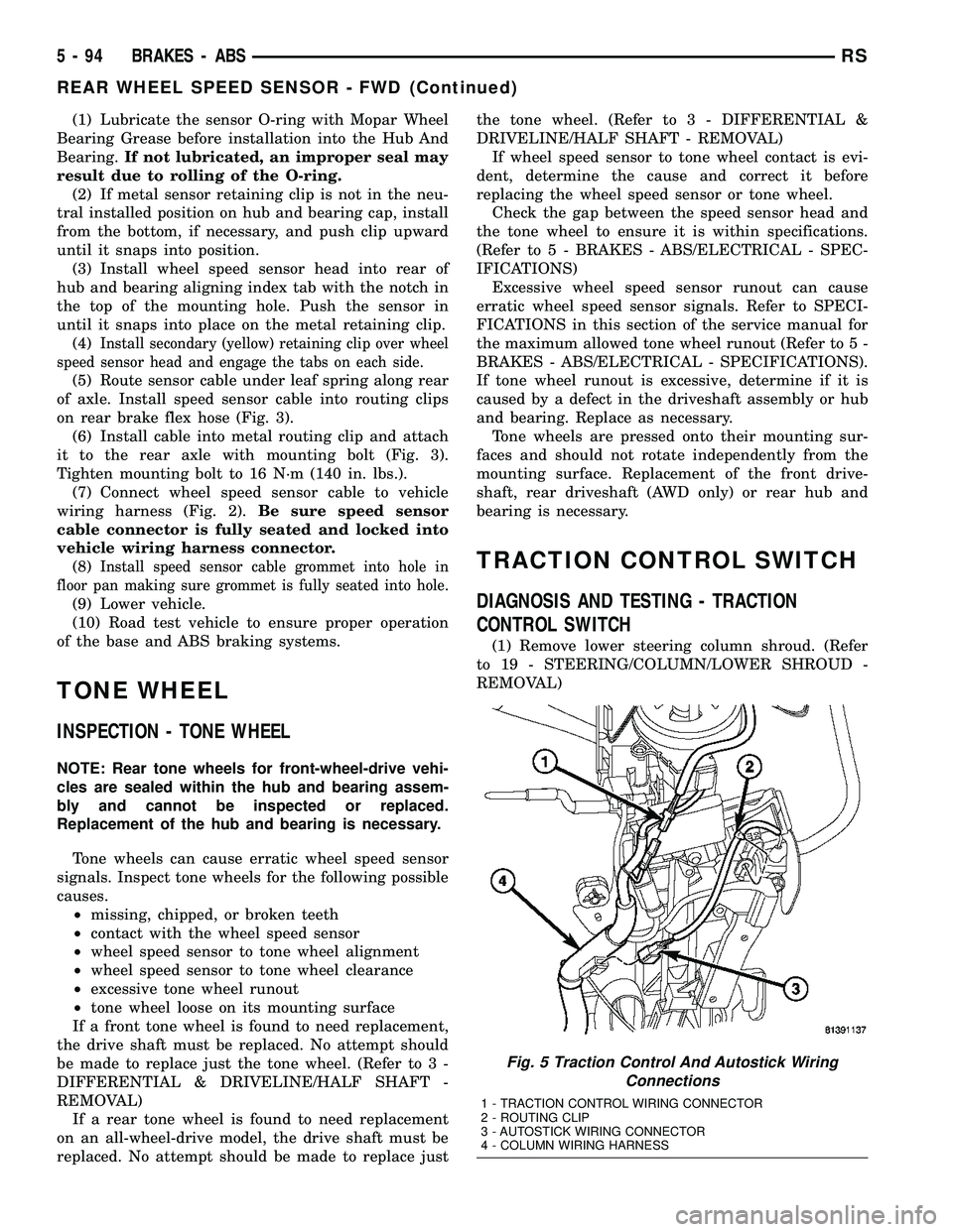
Fig. 5 Traction Control And Autostick Wiring
Connections
1 - TRACTION CONTROL WIRING CONNECTOR
2 - ROUTING CLIP
3 - AUTOSTICK WIRING CONNECTOR
4 - COLUMN WIRING HARNESS
5 - 94 BRAKES - ABSRS
REAR WHEEL SPEED SENSOR - FWD (Continued)
Page 297 of 2339
²SCI Receive
²Speed Control
²Throttle Position Sensor
²Transmission Control Relay (Switched B+)
²Transmission Pressure Switches
²Transmission Temperature Sensor
²Transmission Input Shaft Speed Sensor
²Transmission Output Shaft Speed Sensor
²Transaxle Gear Engagement
²Vehicle Speed
NOTE: PCM Outputs:
²Air Conditioning Clutch Relay
²Automatic Shut Down (ASD) and Fuel Pump
Relays
²Data Link Connector (PCI and SCI Transmit)
²Double Start Override
²EGR Solenoid
²Fuel Injectors
²Generator Field
²High Speed Fan Relay
²Idle Air Control Motor
²Ignition Coils
²Leak Detection Pump
²Low Speed Fan Relay
²MTV Actuator
²Proportional Purge Solenoid
²SRV Valve
²Speed Control Relay
²Speed Control Vent Relay
²Speed Control Vacuum Relay
²8 Volt Output
²5 Volt Output
²Torque Reduction Request
²Transmission Control Relay
²Transmission Solenoids
²Vehicle Speed
Based on inputs it receives, the powertrain control
module (PCM) adjusts fuel injector pulse width, idle
speed, ignition timing, and canister purge operation.
The PCM regulates the cooling fans, air conditioning
and speed control systems. The PCM changes gener-
ator charge rate by adjusting the generator field.
The PCM adjusts injector pulse width (air-fuel
ratio) based on the following inputs.
²Battery Voltage
²Intake Air Temperature Sensor
²Engine Coolant Temperature
²Engine Speed (crankshaft position sensor)
²Exhaust Gas Oxygen Content (heated oxygen
sensors)
²Manifold Absolute Pressure
²Throttle Position
The PCM adjusts engine idle speed through the
idle air control motor based on the following inputs.
²Brake Switch²Engine Coolant Temperature
²Engine Speed (crankshaft position sensor)
²Park/Neutral
²Transaxle Gear Engagement
²Throttle Position
²Vehicle Speed
The PCM adjusts ignition timing based on the fol-
lowing inputs.
²Intake Air Temperature
²Engine Coolant Temperature
²Engine Speed (crankshaft position sensor)
²Knock Sensor
²Manifold Absolute Pressure
²Park/Neutral
²Transaxle Gear Engagement
²Throttle Position
The automatic shut down (ASD) and fuel pump
relays are mounted externally, but turned on and off
by the powertrain control module through the same
circuit.
The camshaft and crankshaft signals are sent to
the powertrain control module. If the PCM does not
receive both signals within approximately one second
of engine cranking, it deactivates the ASD and fuel
pump relays. When these relays are deactivated,
power is shut off to the fuel injectors, ignition coils,
fuel pump and the heating element in each oxygen
sensor.
The PCM contains a voltage converter that
changes battery voltage to a regulated 8.0 volts. The
8.0 volts power the camshaft position sensor, crank-
shaft position sensor and vehicle speed sensor. The
PCM also provides a 5.0 volts supply for the engine
coolant temperature sensor, intake air temperature
sensor, manifold absolute pressure sensor and throt-
tle position sensor.
The PCM engine control strategy prevents reduced
idle speeds until after the engine operates for 320 km
(200 miles). If the PCM is replaced after 320 km (200
miles) of usage, update the mileage in new PCM. Use
the DRBIIItscan tool to change the mileage in the
PCM. Refer to the appropriate Powertrain Diagnostic
Manual and the DRBIIItscan tool.
TRANSMISSION CONTROL
CLUTCH VOLUME INDEX (CVI)
An important function of the PCM is to monitor
Clutch Volume Index (CVI). CVIs represent the vol-
ume of fluid needed to compress a clutch pack.
The PCM monitors gear ratio changes by monitor-
ing the Input and Output Speed Sensors. The Input,
or Turbine Speed Sensor sends an electrical signal to
the PCM that represents input shaft rpm. The Out-
put Speed Sensor provides the PCM with output
shaft speed information.
8E - 12 ELECTRONIC CONTROL MODULESRS
POWERTRAIN CONTROL MODULE (Continued)
Page 391 of 2339
(b) Install the switch in its bracket by aligning
the index tab on the switch with the slot in the
mounting bracket.
(c) When the switch is fully seated in its
bracket, rotate the switch clockwise approximately
30É to lock the switch into place.
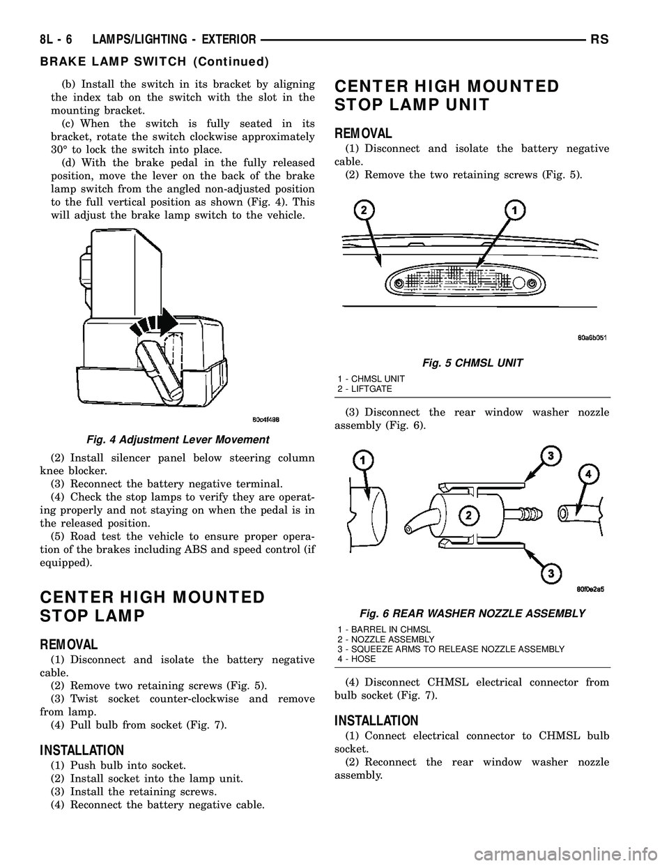
(d) With the brake pedal in the fully released
position, move the lever on the back of the brake
lamp switch from the angled non-adjusted position
to the full vertical position as shown (Fig. 4). This
will adjust the brake lamp switch to the vehicle.
(2) Install silencer panel below steering column
knee blocker.
(3) Reconnect the battery negative terminal.
(4) Check the stop lamps to verify they are operat-
ing properly and not staying on when the pedal is in
the released position.
(5) Road test the vehicle to ensure proper opera-
tion of the brakes including ABS and speed control (if
equipped).
CENTER HIGH MOUNTED
STOP LAMP
REMOVAL
(1) Disconnect and isolate the battery negative
cable.
(2) Remove two retaining screws (Fig. 5).
(3) Twist socket counter-clockwise and remove
from lamp.
(4) Pull bulb from socket (Fig. 7).
INSTALLATION
(1) Push bulb into socket.
(2) Install socket into the lamp unit.
(3) Install the retaining screws.
(4) Reconnect the battery negative cable.
CENTER HIGH MOUNTED
STOP LAMP UNIT
REMOVAL
(1) Disconnect and isolate the battery negative
cable.
(2) Remove the two retaining screws (Fig. 5).
(3) Disconnect the rear window washer nozzle
assembly (Fig. 6).
(4) Disconnect CHMSL electrical connector from
bulb socket (Fig. 7).
INSTALLATION
(1) Connect electrical connector to CHMSL bulb
socket.
(2) Reconnect the rear window washer nozzle
assembly.
Fig. 4 Adjustment Lever Movement
Fig. 5 CHMSL UNIT
1 - CHMSL UNIT
2 - LIFTGATE
Fig. 6 REAR WASHER NOZZLE ASSEMBLY
1 - BARREL IN CHMSL
2 - NOZZLE ASSEMBLY
3 - SQUEEZE ARMS TO RELEASE NOZZLE ASSEMBLY
4 - HOSE
8L - 6 LAMPS/LIGHTING - EXTERIORRS
BRAKE LAMP SWITCH (Continued)
Page 498 of 2339
Service replacement clocksprings are shipped pre-
centered and with a molded plastic shield that snaps
onto the rotor over the release button. The release
button secures the centered clockspring rotor to the
clockspring case and the shield prevents the release
button from being inadvertently depressed during
shipment and handling, but the shield must be
removed from the clockspring after it is installed on
the steering column (Refer to 8 - ELECTRICAL/RE-
STRAINTS/CLOCKSPRING - STANDARD PROCE-
DURE).
The clockspring cannot be repaired. If the clock-
spring is faulty, damaged, or if the driver airbag has
been deployed, the clockspring must be replaced.
OPERATION
The clockspring is a mechanical electrical circuit
component that is used to provide continuous electri-
cal continuity between the fixed instrument panel
wire harness and the electrical components mounted
on or in the rotating steering wheel. The rotating
electrical components include the driver airbag, the
horn switch, the speed control switches, and the
remote radio switches, if the vehicle is so equipped.
The clockspring case is positioned and secured to the
upper steering column housing near the top of the
steering column. The connector receptacles on the
tail of the clockspring case connect the clockspring to
the vehicle electrical system through two connectors
from the instrument panel wire harness.
The clockspring rotor is movable and is keyed by
the tower formation that is molded onto the upper
surface of the rotor hub to an opening that is cast
into the steering wheel armature. Rubber bumper
blocks on either side of the clockspring tower forma-
tion eliminate contact noise between the clockspring
tower and the steering wheel. The lobe of the turn
signal cancel cam on the lower surface of the clock-
spring rotor hub contacts a turn signal cancel actua-
tor of the multi-function switch to provide automatic
turn signal cancellation. The yellow or black-sleeved
pigtail wires on the upper surface of the clockspring
rotor connect the clockspring to the driver airbag,
while a steering wheel wire harness connects the
connector receptacle on the upper surface of the
clockspring rotor to the horn switch and, if the vehi-
cle is so equipped, to the optional speed control
switches and remote radio switches on the steering
wheel.
The clockspring tape has travel limits and can be
damaged by being wound too tightly during full stop-
to-stop steering wheel rotation. To prevent this from
occurring, the clockspring is centered when it is
installed on the steering column. Centering the clock-
spring indexes the clockspring tape to the movable
steering components so that the tape can operatewithin its designed travel limits. However, if the
clockspring is removed from the steering column or if
the steering shaft is disconnected from the steering
gear, the clockspring spool can change position rela-
tive to the movable steering components and must be
re-centered following completion of the service or the
tape may be damaged (Refer to 8 - ELECTRICAL/
RESTRAINTS/CLOCKSPRING - STANDARD PRO-
CEDURE).
Service replacement clocksprings are shipped pre-
centered and with a plastic shield installed over the
clockspring release button. This shield should not be
removed and the release button should not be
depressed until the clockspring has been installed on
the steering column. If the release button is
depressed before the clockspring is installed on a
steering column, the clockspring centering procedure
must be performed (Refer to 8 - ELECTRICAL/RE-
STRAINTS/CLOCKSPRING - STANDARD PROCE-
DURE).
STANDARD PROCEDURE - CLOCKSPRING
CENTERING
If the rotating tape (wire coil) in the clockspring is
not positioned properly with the steering wheel and
the front wheels, the clockspring may fail. The fol-
lowing procedure MUST BE USED to center the
clockspring if it is not known to be properly posi-
tioned, or if the front wheels were moved from the
straight ahead position.
(1) Position steering wheel and front wheels
straight ahead.
(2) Release hood latch and open hood.
(3) Disconnect and isolate the battery negative
cable.
(4) Wait two minutes for the system reserve capac-
itor to discharge before beginning any airbag compo-
nent service.
(5) Remove driver airbag from steering wheel
(Refer to 8 - ELECTRICAL/RESTRAINTS/DRIVER
AIRBAG - REMOVAL).
(6) Disconnect wire connectors from back of driver
airbag.
(7) Disconnect the 2±way connector from remote
radio control harness (if equipped).
(8) Disconnect the 4±way harness connector from
the speed control (if equipped)/horn harness to the
clockspring.
(9) Remove steering wheel (Refer to 19 - STEER-
ING/COLUMN/STEERING WHEEL - REMOVAL).
(10) Rotate the clockspring rotor clockwise until
the rotor stops. Do not apply excessive force.
(11) From the end of travel, rotate the rotor two
turns counterclockwise until the wires end up at the
top.
RSRESTRAINTS8O-11
CLOCKSPRING (Continued)
Page 519 of 2339
(38) Remove the two passenger airbag to instru-
ment panel cover/pad retaining screws.
(39) Remove the three passenger airbag to instru-
ment panel reinforcement retaining bolts.
(40) Pull rearward slightly on the instrument
panel cover/pad to maneuver passenger airbag out
from reinforcement and instrument panel.
INSTALLATION
DEPLOYED AIRBAG
Transfer all reusable components to the new
instrument panel.
(1) Install new Passenger Airbag into instrument
panel.
(2) Install airbag attaching bolts to the instrument
panel.
(a) Torque the two bolts at instrument panel
retainer bosses to 2.7 .5 N´m (24 5 in. lbs.).
(b) Torque the three bolts that attach the pas-
senger airbag to cross-car beam to 10 2 N´m (90
15 in. lbs.).
(3) Connect yellow wire connector to passenger air-
bag and affix connector to instrument panel rein-
forcement with push pins.
(4) Install Instrument panel (Refer to 23 - BODY/
INSTRUMENT PANEL/INSTRUMENT PANEL
ASSEMBLY - INSTALLATION).
WARNING: Do not connect the battery negative
cable (Refer to 8 - ELECTRICAL/RESTRAINTS -
DIAGNOSIS AND TESTING - AIRBAG SYSTEM). Per-
sonal injury or death may result if the system test
is not performed first.
UNDEPLOYED AIRBAG
(1) Pull rearward slightly on the instrument panel
cover/pad to maneuver passenger airbag up onto
reinforcement and instrument panel.
(2) Install the three passenger airbag to instru-
ment panel reinforcement retaining bolts but leave
loose. This will help align the passenger airbag for
the cover/pad fit.
(3) Install the two passenger airbag to instrument
panel cover/pad retaining screws. Torque screws to
2.7 .5 N´m (24 5 in. lbs.).
NOTE: Insure that the instrument panel cover/pad
locator pins are indexed properly at center stack
area prior to reassembly.
(4) Tighten the three passenger airbag to instru-
ment panel reinforcement retaining bolts. Torque
bolts to 10 2 N´m (90 15 in. lbs.).(5) Connect the passenger airbag electrical connec-
tor. Install the connector onto the instrument panel
reinforcement with the push-pin fasteners.
(6) Roll the instrument panel forward lifting
slightly so as to seat the instrument panel air distri-
bution duct on top of the HVAC unit properly to
avoid any leaks or damage to the seal.
(7) Install six upper fence line instrument panel
retaining bolts.
(8) Install three right side instrument panel A-pil-
lar retaining bolts and tighten the right instrument
panel roll down bolt. Install the smaller 10 mm bolt
first to align the instrument panel properly.
(9) Install three left side instrument panel A-pillar
retaining bolts and tighten the left instrument panel
roll down bolt. Install the smaller 10 mm bolt first to
align the instrument panel properly.
(10) Install seven lower instrument panel cover/
pad retaining screws.
(11) Install four screws along top front edge of
instrument panel cover/pad.
(12) Install one far left instrument panel speaker
retaining screw.
(13) Install wiring connectors to radio. Install
radio and four retaining screws.
(14) Connect glove box lamp wiring connector and
place right lower instrument panel trim (glove box
surround) into position.
(15) Install nineteen right lower instrument panel
trim (glove box surround) and install panel screws.
(16) Slide cup holder assembly into instrument
panel.
(17) Install center bezel wiring connectors to
HVAC control and switch assembly (hazard, rear
wiper/washer, heated seats).
(18) Install instrument panel center bezel by align-
ing slots and firmly snapping into place.
(19) Install two screws to instrument panel center
bezel.
(20) Align filler bezel above cup holder over retain-
ing slots and firmly snap into place.
(21) Place instrument panel top cover into position
and firmly snap down rear edge of top cover.
(22) Install glove box. Align hinges, snap into
place, roll glove box upwards and push in sides to
fully install.
(23) Align right side upper A-pillar trim over
retaining slots and firmly snap into place.
(24) Align right A-pillar lower extension trim over
retaining slots and firmly snap into place.
(25) Align right instrument panel end cap over
retaining slots and firmly snap into place.
(26) Align right cowl panel over retaining slots and
firmly snap into place.
(27) Align right front door sill plate over retaining
slots and firmly snap into place.
8O - 32 RESTRAINTSRS
PASSENGER AIRBAG (Continued)