change time CHRYSLER CARAVAN 2005 Service Manual
[x] Cancel search | Manufacturer: CHRYSLER, Model Year: 2005, Model line: CARAVAN, Model: CHRYSLER CARAVAN 2005Pages: 2339, PDF Size: 59.69 MB
Page 17 of 2339
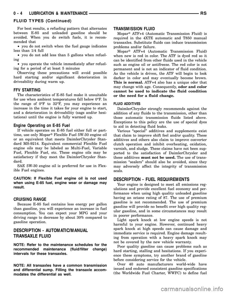
For best results, a refueling pattern that alternates
between E-85 and unleaded gasoline should be
avoided. When you do switch fuels, it is recom-
mended that
┬▓you do not switch when the fuel gauge indicates
less than 1/4 full
┬▓you do not add less than 5 gallons when refuel-
ing
┬▓you operate the vehicle immediately after refuel-
ing for a period of at least 5 minutes
Observing these precautions will avoid possible
hard starting and/or significant deterioration in
driveability during warm up.
FFV STARTING
The characteristics of E-85 fuel make it unsuitable
for use when ambient temperatures fall below 0ÉF. In
the range of 0ÉF to 32ÉF, you may experience an
increase in the time it takes for your engine to start,
and a deterioration in driveability (sags and/or hesi-
tations) until the engine is fully warmed up.
Engine Operating on E-85 Fuel
If vehicle operates on E-85 fuel either full or part-
time, use only MopartFlexible Fuel 5W-30 engine oil
or an equivalent that meets DaimlerChrysler Stan-
dard MS-9214. Equivalent commercial Flexible Fuel
engine oils may be labeled as Multi-Fuel, Variable
Fuel, Flexible Fuel, etc. These engine oils may be
satisfactory if they meet the DaimlerChrysler Stan-
dard.
SAE 5W-30 engine oil is preferred for use in Flex-
ible Fuel engines.
CAUTION: If Flexible Fuel engine oil is not used
when using E-85 fuel, engine wear or damage may
result.
CRUISING RANGE
Because E-85 fuel contains less energy per gallon
than gasoline, you will experience an increase in fuel
consumption. You can expect your MPG and your
driving range to decrease by about 30% compared to
gasoline operation.
DESCRIPTION - AUTOMATIC/MANUAL
TRANSAXLE FLUID
NOTE: Refer to the maintenance schedules for the
recommended maintenance (fluid/filter change)
intervals for these transaxles.
NOTE: All transaxles have a common transmission
and differential sump. Filling the transaxle accom-
modates the differential as well.
TRANSMISSION FLUID
MopartATF+4 (Automatic Transmission Fluid) is
required in the 4XTE automatic and T850 manual
transaxles. Substitute fluids can induce transmission
problems and/or failure.
MopartATF+4 (Automatic Transmission Fluid)
when new is red in color. The ATF is dyed red so it
can be identified from other fluids used in the vehicle
such as engine oil or antifreeze. The red color is not
permanent and is not an indicator of fluid condition.
As the vehicle is driven, the ATF will begin to look
darker in color and may eventually become brown.
This is normal.ATF+4 also has a unique odor that
may change with age. Consequently,odor and color
cannot be used to indicate the fluid condition
or the need for a fluid change.
FLUID ADDITIVES
DaimlerChrysler strongly recommends against the
addition of any fluids to the transmission, other than
those automatic transmission fluids listed above.
Exceptions to this policy are the use of special dyes
to aid in detecting fluid leaks.
Various ªspecialº additives and supplements exist
that claim to improve shift feel and/or quality. These
additives and others also claim to improve converter
clutch operation and inhibit overheating, oxidation,
varnish, and sludge. These claims have not been sup-
ported to the satisfaction of DaimlerChrysler and
these additivesmust not be used.The use of trans-
mission ªsealersº should also be avoided, since they
may adversely affect the integrity of transmission
seals.
DESCRIPTION - FUEL REQUIREMENTS
Your engine is designed to meet all emissions reg-
ulations and provide excellent fuel economy and per-
formance when using high quality unleaded gasoline
having an octane rating of 87. The use of premium
gasoline is not recommended. The use of premium
gasoline will provide no benefit over high quality reg-
ular gasoline, and in some circumstances may result
in poorer performance.
Light spark knock at low engine speeds is not
harmful to your engine. However, continued heavy
spark knock at high speeds can cause damage and
immediate service is required. Engine damage result-
ing from operation with a heavy spark knock may
not be covered by the new vehicle warranty.
Poor quality gasoline can cause problems such as
hard starting, stalling and hesitations. If you experi-
ence these symptoms, try another brand of gasoline
before considering service for the vehicle.
Over 40 auto manufacturers world-wide have
issued and endorsed consistent gasoline specifications
(the Worldwide Fuel Charter, WWFC) to define fuel
0 - 4 LUBRICATION & MAINTENANCERS
FLUID TYPES (Continued)
Page 20 of 2339
FLUID FILL/CHECK
LOCATIONS
DESCRIPTION
The fluid check/fill point locations are located in
each applicable service manual section.
LUBRICATION POINTS
DESCRIPTION
Lubrication point locations are located in each
applicable Sections.
MAINTENANCE SCHEDULES
DESCRIPTION
DESCRIPTION
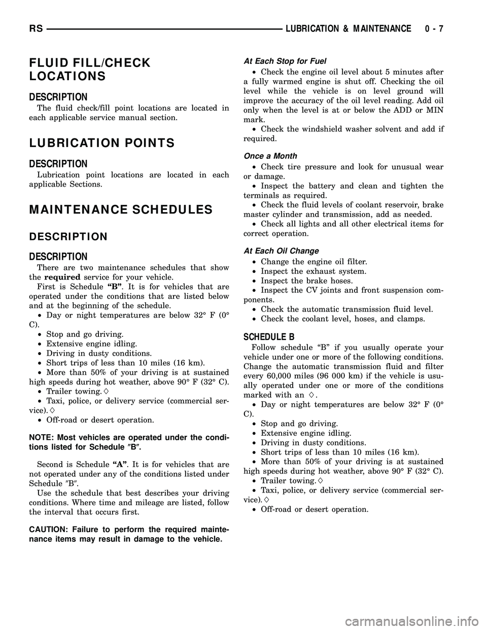
There are two maintenance schedules that show
therequiredservice for your vehicle.
First is ScheduleªBº. It is for vehicles that are
operated under the conditions that are listed below
and at the beginning of the schedule.
²Day or night temperatures are below 32É F (0É
C).
┬▓Stop and go driving.
┬▓Extensive engine idling.
┬▓Driving in dusty conditions.
┬▓Short trips of less than 10 miles (16 km).
┬▓More than 50% of your driving is at sustained
high speeds during hot weather, above 90É F (32É C).
┬▓Trailer towing.L
┬▓Taxi, police, or delivery service (commercial ser-
vice).L
┬▓Off-road or desert operation.
NOTE: Most vehicles are operated under the condi-
tions listed for Schedule(B(.
Second is ScheduleªAº. It is for vehicles that are
not operated under any of the conditions listed under
Schedule9B9.
Use the schedule that best describes your driving
conditions. Where time and mileage are listed, follow
the interval that occurs first.
CAUTION: Failure to perform the required mainte-
nance items may result in damage to the vehicle.
At Each Stop for Fuel
┬▓Check the engine oil level about 5 minutes after
a fully warmed engine is shut off. Checking the oil
level while the vehicle is on level ground will
improve the accuracy of the oil level reading. Add oil
only when the level is at or below the ADD or MIN
mark.
┬▓Check the windshield washer solvent and add if
required.
Once a Month
┬▓Check tire pressure and look for unusual wear
or damage.
┬▓Inspect the battery and clean and tighten the
terminals as required.
┬▓Check the fluid levels of coolant reservoir, brake
master cylinder and transmission, add as needed.
┬▓Check all lights and all other electrical items for
correct operation.
At Each Oil Change
┬▓Change the engine oil filter.
┬▓Inspect the exhaust system.
┬▓Inspect the brake hoses.
┬▓Inspect the CV joints and front suspension com-
ponents.
┬▓Check the automatic transmission fluid level.
┬▓Check the coolant level, hoses, and clamps.
SCHEDULE B
Follow schedule ªBº if you usually operate your
vehicle under one or more of the following conditions.
Change the automatic transmission fluid and filter
every 60,000 miles (96 000 km) if the vehicle is usu-
ally operated under one or more of the conditions
marked with anL.
²Day or night temperatures are below 32É F (0É
C).
┬▓Stop and go driving.
┬▓Extensive engine idling.
┬▓Driving in dusty conditions.
┬▓Short trips of less than 10 miles (16 km).
┬▓More than 50% of your driving is at sustained
high speeds during hot weather, above 90É F (32É C).
┬▓Trailer towing.L
┬▓Taxi, police, or delivery service (commercial ser-
vice).L
┬▓Off-road or desert operation.
RSLUBRICATION & MAINTENANCE0-7
Page 23 of 2339
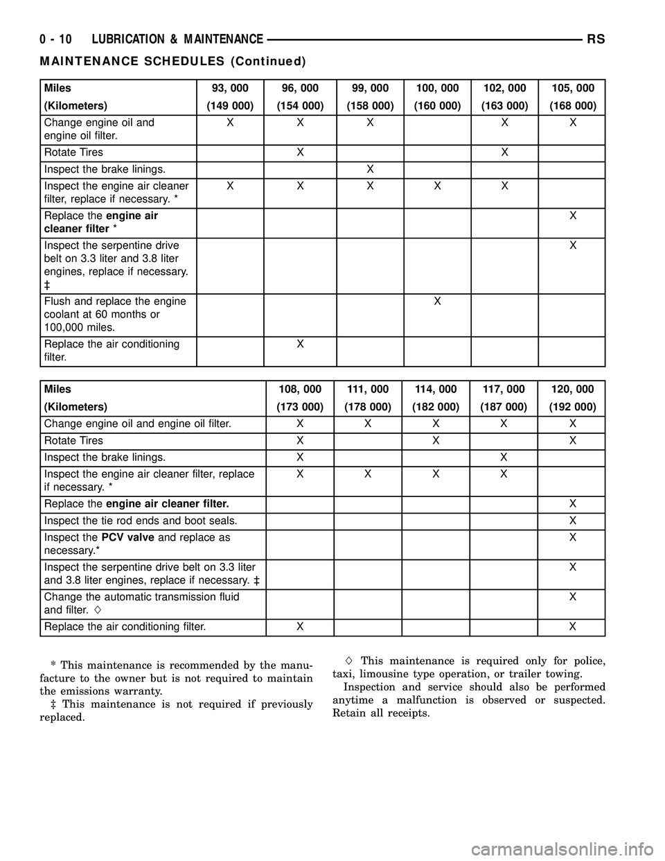
Miles 93, 000 96, 000 99, 000 100, 000 102, 000 105, 000
(Kilometers) (149 000) (154 000) (158 000) (160 000) (163 000) (168 000)
Change engine oil and
engine oil filter.XXX XX
Rotate Tires X X
Inspect the brake linings. X
Inspect the engine air cleaner
filter, replace if necessary. *X X XXX
Replace theengine air
cleaner filter*X
Inspect the serpentine drive
belt on 3.3 liter and 3.8 liter
engines, replace if necessary.
┬│X
Flush and replace the engine
coolant at 60 months or
100,000 miles.X
Replace the air conditioning
filter.X
Miles 108, 000 111, 000 114, 000 117, 000 120, 000
(Kilometers) (173 000) (178 000) (182 000) (187 000) (192 000)
Change engine oil and engine oil filter.XXXX X
Rotate Tires X X X
Inspect the brake linings. X X
Inspect the engine air cleaner filter, replace
if necessary. *XXXX
Replace theengine air cleaner filter.X
Inspect the tie rod ends and boot seals. X
Inspect thePCV valveand replace as
necessary.*X
Inspect the serpentine drive belt on 3.3 liter
and 3.8 liter engines, replace if necessary. ┬│X
Change the automatic transmission fluid
and filter.LX
Replace the air conditioning filter. X X
* This maintenance is recommended by the manu-
facture to the owner but is not required to maintain
the emissions warranty.
┬│ This maintenance is not required if previously
replaced.LThis maintenance is required only for police,
taxi, limousine type operation, or trailer towing.
Inspection and service should also be performed
anytime a malfunction is observed or suspected.
Retain all receipts.
0 - 10 LUBRICATION & MAINTENANCERS
MAINTENANCE SCHEDULES (Continued)
Page 25 of 2339
![CHRYSLER CARAVAN 2005 Service Manual Miles 78, 000 84, 000 90, 000 96, 000 100, 000
(Kilometers) (125 000) (134 000) (144 000) (154 000) (160 000)
[Months] [78] [84] [90] [96]
Change engine oil and engine oil filter.XXXX
Rotate TiresXXXX CHRYSLER CARAVAN 2005 Service Manual Miles 78, 000 84, 000 90, 000 96, 000 100, 000
(Kilometers) (125 000) (134 000) (144 000) (154 000) (160 000)
[Months] [78] [84] [90] [96]
Change engine oil and engine oil filter.XXXX
Rotate TiresXXXX](/img/25/56862/w960_56862-24.png)
Miles 78, 000 84, 000 90, 000 96, 000 100, 000
(Kilometers) (125 000) (134 000) (144 000) (154 000) (160 000)
[Months] [78] [84] [90] [96]
Change engine oil and engine oil filter.XXXX
Rotate TiresXXXX
Inspect the brake linings. X
Inspect the engine air cleaner filter, replace
if necessary. *XX X X
Replace theengine air cleaner filter.X
Inspect the tie rod ends and boot seals. X
Check and replace thePCV valve,if
necessary.*X
Inspect the serpentine drive belt on 3.3 liter
and 3.8 liter engines, replace if necessary. ┬│X
Replace thespark plugs3.3 liter and 3.8
liter engines.X
Replace theignition cables3.3 liter and
3.8 liter engines.X
Flush and replace the engine coolant at
100,000 miles, if not done at 60 months.X
Replace the air conditioning filter. X X
Miles 102, 000 108, 000 114, 000 120, 000
(Kilometers) (163 000) (173 000) (182 000) (192 000)
[Months] [102] [108] [114] [120]
Change engine oil and engine oil filter. X X X X
Rotate Tires X X X X
Inspect the brake linings. X
Inspect the engine air cleaner filter, replace if necessary. * X X X
Replace theengine air cleaner filter.X
Inspect the tie rod ends and boot seals. X
Check thePCV valveand replace, if necessary.* X
Inspect the serpentine drive belt on 3.3 liter and 3.8 liter
engines, replace if necessary. ┬│XX
Flush and replace the engine coolant at 120 months, if
not done at 100,000 miles (160 000 km).X
Replace the air conditioning filter. X X
* This maintenance is recommended by the manu-
facture to the owner but is not required to maintain
the emissions warranty.
┬│ This maintenance is not required if previously
replaced.
Inspection and service should also be performed
anytime a malfunction is observed or suspected.
Retain all receipts.WARNING: You can be badly injured working on or
around a motor vehicle. Do only that service work
for which you have the knowledge and the right
equipment. If you have any doubt about your ability
to perform a service job, take your vehicle to a
competent mechanic.
0 - 12 LUBRICATION & MAINTENANCERS
MAINTENANCE SCHEDULES (Continued)
Page 26 of 2339
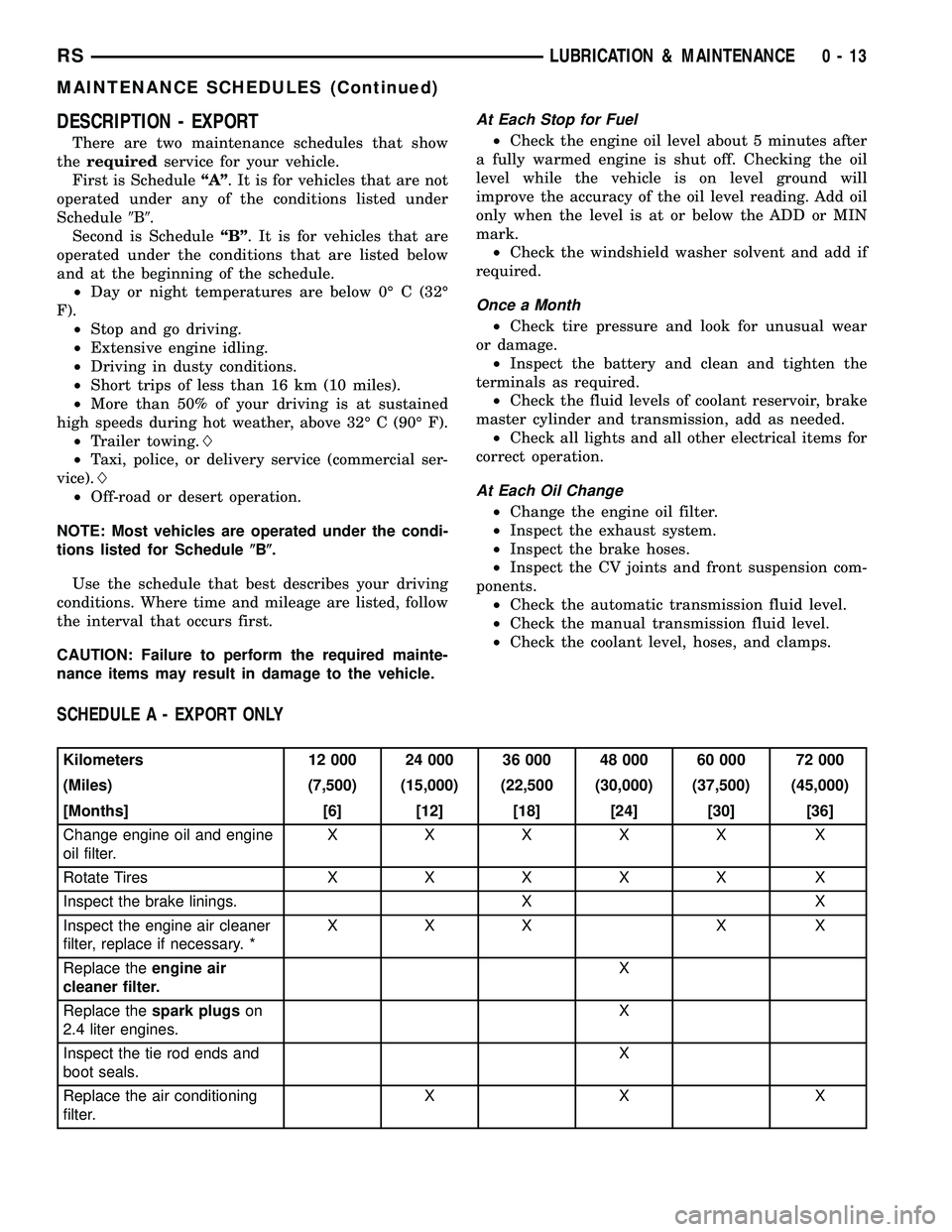
DESCRIPTION - EXPORT
There are two maintenance schedules that show
therequiredservice for your vehicle.
First is ScheduleªAº. It is for vehicles that are not
operated under any of the conditions listed under
Schedule9B9.
Second is ScheduleªBº. It is for vehicles that are
operated under the conditions that are listed below
and at the beginning of the schedule.
²Day or night temperatures are below 0É C (32É
F).
┬▓Stop and go driving.
┬▓Extensive engine idling.
┬▓Driving in dusty conditions.
┬▓Short trips of less than 16 km (10 miles).
┬▓More than 50% of your driving is at sustained
high speeds during hot weather, above 32É C (90É F).
┬▓Trailer towing.L
┬▓Taxi, police, or delivery service (commercial ser-
vice).L
┬▓Off-road or desert operation.
NOTE: Most vehicles are operated under the condi-
tions listed for Schedule(B(.
Use the schedule that best describes your driving
conditions. Where time and mileage are listed, follow
the interval that occurs first.
CAUTION: Failure to perform the required mainte-
nance items may result in damage to the vehicle.
At Each Stop for Fuel
┬▓Check the engine oil level about 5 minutes after
a fully warmed engine is shut off. Checking the oil
level while the vehicle is on level ground will
improve the accuracy of the oil level reading. Add oil
only when the level is at or below the ADD or MIN
mark.
┬▓Check the windshield washer solvent and add if
required.
Once a Month
┬▓Check tire pressure and look for unusual wear
or damage.
┬▓Inspect the battery and clean and tighten the
terminals as required.
┬▓Check the fluid levels of coolant reservoir, brake
master cylinder and transmission, add as needed.
┬▓Check all lights and all other electrical items for
correct operation.
At Each Oil Change
┬▓Change the engine oil filter.
┬▓Inspect the exhaust system.
┬▓Inspect the brake hoses.
┬▓Inspect the CV joints and front suspension com-
ponents.
┬▓Check the automatic transmission fluid level.
┬▓Check the manual transmission fluid level.
┬▓Check the coolant level, hoses, and clamps.
SCHEDULE A - EXPORT ONLY
Kilometers 12 000 24 000 36 000 48 000 60 000 72 000
(Miles) (7,500) (15,000) (22,500 (30,000) (37,500) (45,000)
[Months] [6] [12] [18] [24] [30] [36]
Change engine oil and engine
oil filter.XXXXX X
Rotate Tires XXXXX X
Inspect the brake linings. X X
Inspect the engine air cleaner
filter, replace if necessary. *XXX X X
Replace theengine air
cleaner filter.X
Replace thespark plugson
2.4 liter engines.X
Inspect the tie rod ends and
boot seals.X
Replace the air conditioning
filter.XX X
RSLUBRICATION & MAINTENANCE0-13
MAINTENANCE SCHEDULES (Continued)
Page 34 of 2339
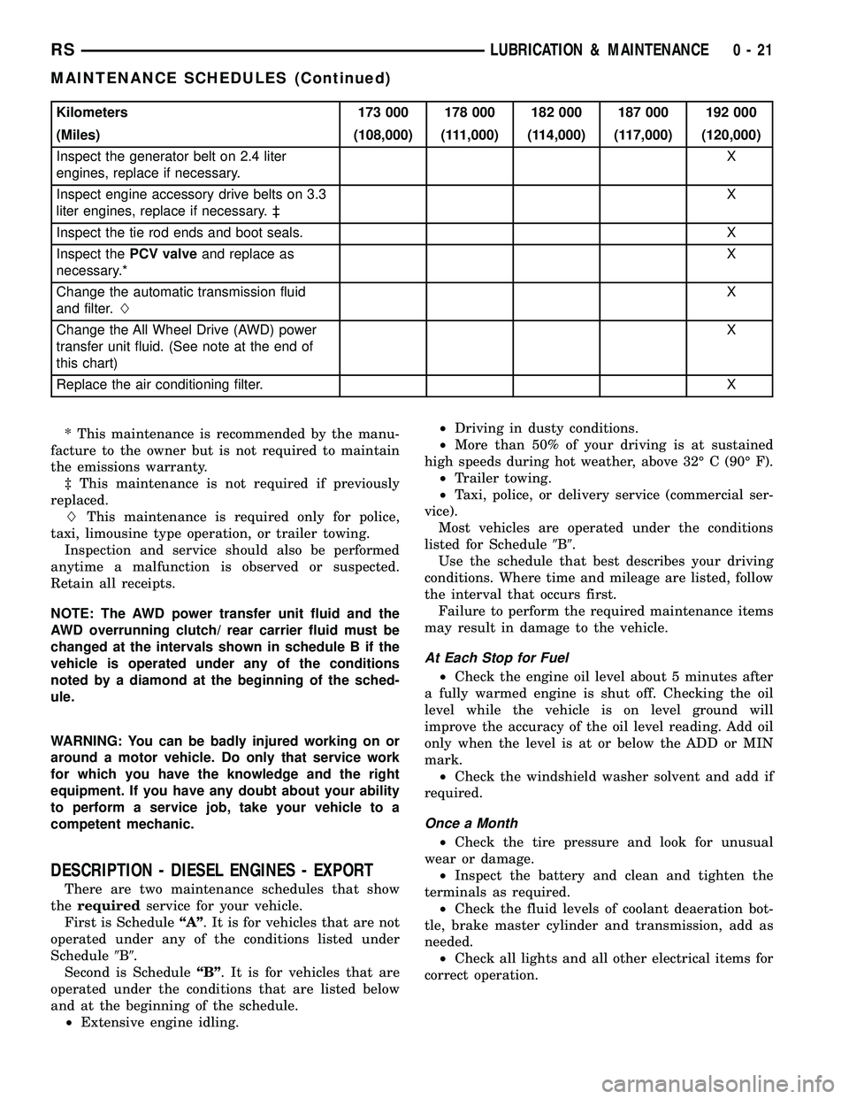
Kilometers 173 000 178 000 182 000 187 000 192 000
(Miles) (108,000) (111,000) (114,000) (117,000) (120,000)
Inspect the generator belt on 2.4 liter
engines, replace if necessary.X
Inspect engine accessory drive belts on 3.3
liter engines, replace if necessary. ┬│X
Inspect the tie rod ends and boot seals. X
Inspect thePCV valveand replace as
necessary.*X
Change the automatic transmission fluid
and filter.LX
Change the All Wheel Drive (AWD) power
transfer unit fluid. (See note at the end of
this chart)X
Replace the air conditioning filter.X
* This maintenance is recommended by the manu-
facture to the owner but is not required to maintain
the emissions warranty.
┬│ This maintenance is not required if previously
replaced.
LThis maintenance is required only for police,
taxi, limousine type operation, or trailer towing.
Inspection and service should also be performed
anytime a malfunction is observed or suspected.
Retain all receipts.
NOTE: The AWD power transfer unit fluid and the
AWD overrunning clutch/ rear carrier fluid must be
changed at the intervals shown in schedule B if the
vehicle is operated under any of the conditions
noted by a diamond at the beginning of the sched-
ule.
WARNING: You can be badly injured working on or
around a motor vehicle. Do only that service work
for which you have the knowledge and the right
equipment. If you have any doubt about your ability
to perform a service job, take your vehicle to a
competent mechanic.
DESCRIPTION - DIESEL ENGINES - EXPORT
There are two maintenance schedules that show
therequiredservice for your vehicle.
First is ScheduleªAº. It is for vehicles that are not
operated under any of the conditions listed under
Schedule9B9.
Second is ScheduleªBº. It is for vehicles that are
operated under the conditions that are listed below
and at the beginning of the schedule.
┬▓Extensive engine idling.┬▓Driving in dusty conditions.
┬▓More than 50% of your driving is at sustained
high speeds during hot weather, above 32É C (90É F).
┬▓Trailer towing.
┬▓Taxi, police, or delivery service (commercial ser-
vice).
Most vehicles are operated under the conditions
listed for Schedule9B9.
Use the schedule that best describes your driving
conditions. Where time and mileage are listed, follow
the interval that occurs first.
Failure to perform the required maintenance items
may result in damage to the vehicle.
At Each Stop for Fuel
┬▓Check the engine oil level about 5 minutes after
a fully warmed engine is shut off. Checking the oil
level while the vehicle is on level ground will
improve the accuracy of the oil level reading. Add oil
only when the level is at or below the ADD or MIN
mark.
┬▓Check the windshield washer solvent and add if
required.
Once a Month
┬▓Check the tire pressure and look for unusual
wear or damage.
┬▓Inspect the battery and clean and tighten the
terminals as required.
┬▓Check the fluid levels of coolant deaeration bot-
tle, brake master cylinder and transmission, add as
needed.
┬▓Check all lights and all other electrical items for
correct operation.
RSLUBRICATION & MAINTENANCE0-21
MAINTENANCE SCHEDULES (Continued)
Page 35 of 2339
At Each Oil Change
┬▓Change the engine oil filter.
┬▓Inspect the exhaust system.
┬▓Inspect the brake hoses.
┬▓Inspect the CV joints and front suspension com-
ponents.┬▓Check the manual transmission fluid level.
┬▓Check the coolant level, hoses, and clamps.
┬▓Inspect engine accessory drive belts. Replace as
necessary.
┬▓Inspect for the presence of water in the fuel fil-
ter/water separator unit.
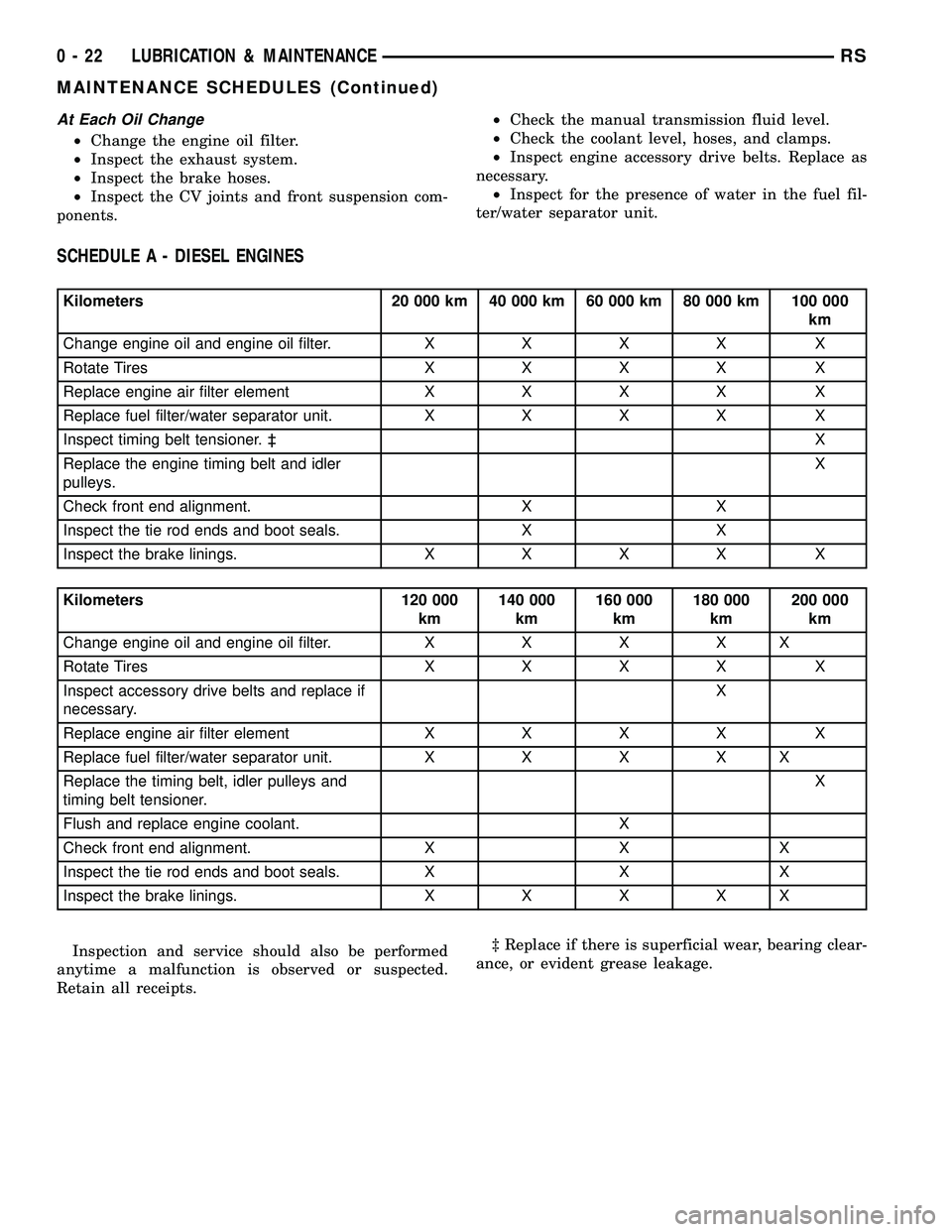
SCHEDULE A - DIESEL ENGINES
Kilometers 20 000 km 40 000 km 60 000 km 80 000 km 100 000
km
Change engine oil and engine oil filter.XXXX X
Rotate TiresXXXX X
Replace engine air filter elementXXXX X
Replace fuel filter/water separator unit.XXXX X
Inspect timing belt tensioner. ┬│X
Replace the engine timing belt and idler
pulleys.X
Check front end alignment. X X
Inspect the tie rod ends and boot seals. X X
Inspect the brake linings.XXXX X
Kilometers 120 000
km140 000
km160 000
km180 000
km200 000
km
Change engine oil and engine oil filter.XXXXX
Rotate TiresXXXX X
Inspect accessory drive belts and replace if
necessary.X
Replace engine air filter elementXXXX X
Replace fuel filter/water separator unit.XXXXX
Replace the timing belt, idler pulleys and
timing belt tensioner.X
Flush and replace engine coolant. X
Check front end alignment. X X X
Inspect the tie rod ends and boot seals. X X X
Inspect the brake linings.XXXXX
Inspection and service should also be performed
anytime a malfunction is observed or suspected.
Retain all receipts.┬│ Replace if there is superficial wear, bearing clear-
ance, or evident grease leakage.
0 - 22 LUBRICATION & MAINTENANCERS
MAINTENANCE SCHEDULES (Continued)
Page 46 of 2339
HUB / BEARING
DESCRIPTION
The front wheel bearing and front wheel hub of
this vehicle are a hub and bearing unit type assem-
bly (Unit III). This unit combines the front wheel
mounting hub (flange) and the front wheel bearing
into a sealed one-piece unit. The hub and bearing is
mounted to the center of the steering knuckle (Fig.
1). It is retained by four mounting bolts accessible
from the inboard side of the steering knuckle. The
hub flange has five wheel mounting studs.
The wheel mounting studs used to mount the tire
and wheel to the vehicle are the only replaceable
components of the hub and bearing assembly. Other-
wise, the hub and bearing is serviced only as a com-
plete assembly.
OPERATION
The hub and bearing has internal bearings that
allow the hub to rotate with the driveshaft, along
with the tire and wheel. The five wheel mounting
studs mount the tire and wheel, and brake rotor to
the vehicle.
DIAGNOSIS AND TESTING - HUB AND
BEARING
The condition of the front hub and bearing assem-
bly is diagnosed using the inspection and testing pro-
cedure detailed below.
The bearing contained in the Unit III front hub/
bearing assembly will produce noise and vibration
when worn or damaged. The noise will generally
change when the bearings are loaded. A road test of
the vehicle is normally required to determine the
location of a worn or damaged bearing.
Find a smooth level road surface and bring the
vehicle up to a constant speed. When vehicle is at a
constant speed, swerve the vehicle back and forth
from the left and to the right. This will load and
unload the bearings and change the noise level.
When bearing damage is slight, the noise is some-
times noticeable at lower speeds and at other times
is more noticeable at speeds above 105 km/h (65
mph).
REMOVAL
NOTE: Replacement of the Unit III front hub/bearing
assembly can be normally done without having to
remove the steering knuckle from the vehicle. In the
event that the hub/bearing is frozen in the steering
knuckle and cannot be removed by hand, it will
have to be pressed out of the steering knuckle. The
steering knuckle will require removal from the vehi-
cle to allow the hub/bearing assembly to bepressed out of the steering knuckle. (Refer to 2 -
SUSPENSION/FRONT/KNUCKLE - REMOVAL)
(1) Raise vehicle. (Refer to LUBRICATION &
MAINTENANCE/HOISTING - STANDARD PROCE-
DURE)
(2) Remove wheel lug nuts, and front tire and
wheel assembly.
(3) Remove the cotter pin, nut lock and spring
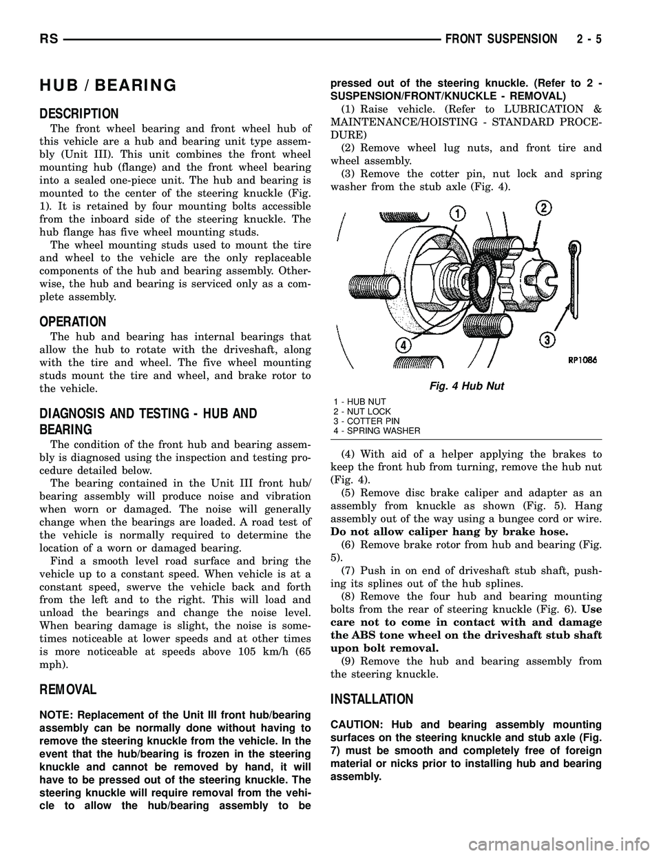
washer from the stub axle (Fig. 4).
(4) With aid of a helper applying the brakes to
keep the front hub from turning, remove the hub nut
(Fig. 4).
(5) Remove disc brake caliper and adapter as an
assembly from knuckle as shown (Fig. 5). Hang
assembly out of the way using a bungee cord or wire.
Do not allow caliper hang by brake hose.
(6) Remove brake rotor from hub and bearing (Fig.
5).
(7) Push in on end of driveshaft stub shaft, push-
ing its splines out of the hub splines.
(8) Remove the four hub and bearing mounting
bolts from the rear of steering knuckle (Fig. 6).Use
care not to come in contact with and damage
the ABS tone wheel on the driveshaft stub shaft
upon bolt removal.
(9) Remove the hub and bearing assembly from
the steering knuckle.
INSTALLATION
CAUTION: Hub and bearing assembly mounting
surfaces on the steering knuckle and stub axle (Fig.
7) must be smooth and completely free of foreign
material or nicks prior to installing hub and bearing
assembly.
Fig. 4 Hub Nut
1 - HUB NUT
2 - NUT LOCK
3 - COTTER PIN
4 - SPRING WASHER
RSFRONT SUSPENSION2-5
Page 72 of 2339
wheel rotates with the hub which is sensed by the
wheel speed sensor.
DIAGNOSIS AND TESTING - HUB AND
BEARING
The bearing contained in the hub and bearing
assembly will produce noise and vibration when worn
or damaged. The noise will generally change when
the bearings are loaded. A road test of the vehicle is
normally required to determine the location of a
worn or damaged bearing.
Find a smooth level road surface and bring the
vehicle up to a constant speed. When vehicle is at a
constant speed, swerve the vehicle back and forth
from the left and to the right. This will load and
unload the bearings and change the noise level.
When bearing damage is slight, the noise is some-
times noticeable at lower speeds and at other times
is more noticeable at speeds above 105 km/h (65
mph).
REMOVAL
FRONT-WHEEL-DRIVE VEHICLES
(1) Raise vehicle. (Refer to LUBRICATION &
MAINTENANCE/HOISTING - STANDARD PROCE-
DURE)
(2) Remove wheel and tire. (Refer to 22 - TIRES/
WHEELS - REMOVAL)
(3) Remove brake drum or disc brake caliper and
rotor from hub and bearing. (Refer to 5 - BRAKES/
HYDRAULIC/MECHANICAL/DRUM - REMOVAL-
)(Refer to 5 - BRAKES/HYDRAULIC/MECHANICAL/
ROTOR - REMOVAL)
(4) If equipped with antilock brakes, perform the
following:
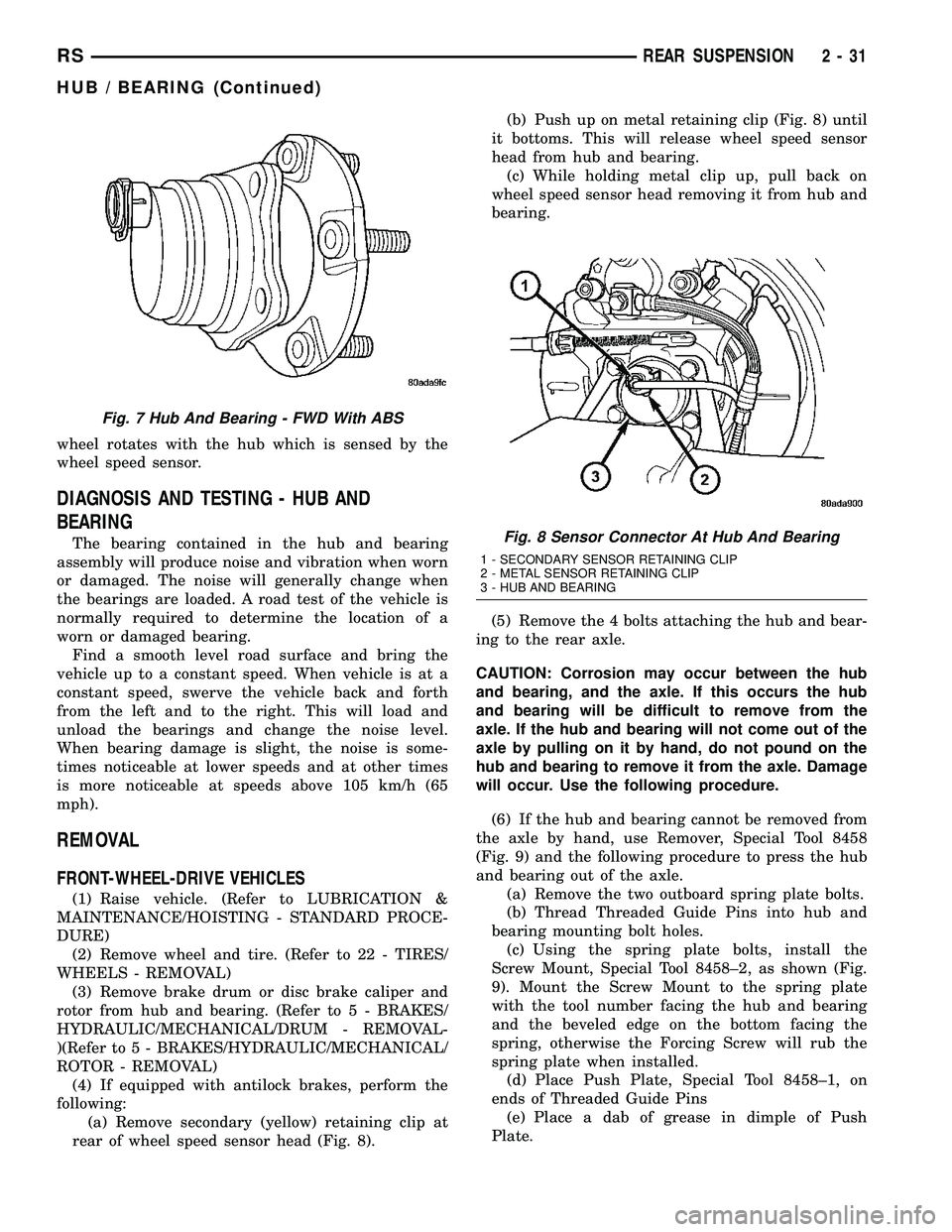
(a) Remove secondary (yellow) retaining clip at
rear of wheel speed sensor head (Fig. 8).(b) Push up on metal retaining clip (Fig. 8) until
it bottoms. This will release wheel speed sensor
head from hub and bearing.
(c) While holding metal clip up, pull back on
wheel speed sensor head removing it from hub and
bearing.
(5) Remove the 4 bolts attaching the hub and bear-
ing to the rear axle.
CAUTION: Corrosion may occur between the hub
and bearing, and the axle. If this occurs the hub
and bearing will be difficult to remove from the
axle. If the hub and bearing will not come out of the
axle by pulling on it by hand, do not pound on the
hub and bearing to remove it from the axle. Damage
will occur. Use the following procedure.
(6) If the hub and bearing cannot be removed from
the axle by hand, use Remover, Special Tool 8458
(Fig. 9) and the following procedure to press the hub
and bearing out of the axle.
(a) Remove the two outboard spring plate bolts.
(b) Thread Threaded Guide Pins into hub and
bearing mounting bolt holes.
(c) Using the spring plate bolts, install the
Screw Mount, Special Tool 8458┬▒2, as shown (Fig.
9). Mount the Screw Mount to the spring plate
with the tool number facing the hub and bearing
and the beveled edge on the bottom facing the
spring, otherwise the Forcing Screw will rub the
spring plate when installed.
(d) Place Push Plate, Special Tool 8458┬▒1, on
ends of Threaded Guide Pins
(e) Place a dab of grease in dimple of Push
Plate.
Fig. 7 Hub And Bearing - FWD With ABS
Fig. 8 Sensor Connector At Hub And Bearing
1 - SECONDARY SENSOR RETAINING CLIP
2 - METAL SENSOR RETAINING CLIP
3 - HUB AND BEARING
RSREAR SUSPENSION2-31
HUB / BEARING (Continued)
Page 125 of 2339
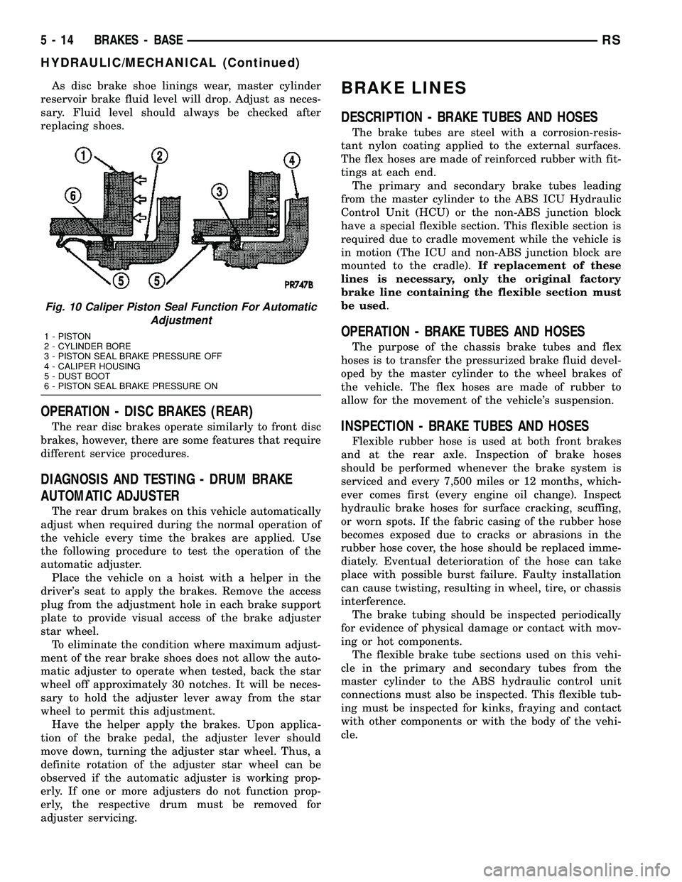
As disc brake shoe linings wear, master cylinder
reservoir brake fluid level will drop. Adjust as neces-
sary. Fluid level should always be checked after
replacing shoes.
OPERATION - DISC BRAKES (REAR)
The rear disc brakes operate similarly to front disc
brakes, however, there are some features that require
different service procedures.
DIAGNOSIS AND TESTING - DRUM BRAKE
AUTOMATIC ADJUSTER
The rear drum brakes on this vehicle automatically
adjust when required during the normal operation of
the vehicle every time the brakes are applied. Use
the following procedure to test the operation of the
automatic adjuster.
Place the vehicle on a hoist with a helper in the
driver's seat to apply the brakes. Remove the access
plug from the adjustment hole in each brake support
plate to provide visual access of the brake adjuster
star wheel.
To eliminate the condition where maximum adjust-
ment of the rear brake shoes does not allow the auto-
matic adjuster to operate when tested, back the star
wheel off approximately 30 notches. It will be neces-
sary to hold the adjuster lever away from the star
wheel to permit this adjustment.
Have the helper apply the brakes. Upon applica-
tion of the brake pedal, the adjuster lever should
move down, turning the adjuster star wheel. Thus, a
definite rotation of the adjuster star wheel can be
observed if the automatic adjuster is working prop-
erly. If one or more adjusters do not function prop-
erly, the respective drum must be removed for
adjuster servicing.
BRAKE LINES
DESCRIPTION - BRAKE TUBES AND HOSES
The brake tubes are steel with a corrosion-resis-
tant nylon coating applied to the external surfaces.
The flex hoses are made of reinforced rubber with fit-
tings at each end.
The primary and secondary brake tubes leading
from the master cylinder to the ABS ICU Hydraulic
Control Unit (HCU) or the non-ABS junction block
have a special flexible section. This flexible section is
required due to cradle movement while the vehicle is
in motion (The ICU and non-ABS junction block are
mounted to the cradle).If replacement of these
lines is necessary, only the original factory
brake line containing the flexible section must
be used.
OPERATION - BRAKE TUBES AND HOSES
The purpose of the chassis brake tubes and flex
hoses is to transfer the pressurized brake fluid devel-
oped by the master cylinder to the wheel brakes of
the vehicle. The flex hoses are made of rubber to
allow for the movement of the vehicle's suspension.
INSPECTION - BRAKE TUBES AND HOSES
Flexible rubber hose is used at both front brakes
and at the rear axle. Inspection of brake hoses
should be performed whenever the brake system is
serviced and every 7,500 miles or 12 months, which-
ever comes first (every engine oil change). Inspect
hydraulic brake hoses for surface cracking, scuffing,
or worn spots. If the fabric casing of the rubber hose
becomes exposed due to cracks or abrasions in the
rubber hose cover, the hose should be replaced imme-
diately. Eventual deterioration of the hose can take
place with possible burst failure. Faulty installation
can cause twisting, resulting in wheel, tire, or chassis
interference.
The brake tubing should be inspected periodically
for evidence of physical damage or contact with mov-
ing or hot components.
The flexible brake tube sections used on this vehi-
cle in the primary and secondary tubes from the
master cylinder to the ABS hydraulic control unit
connections must also be inspected. This flexible tub-
ing must be inspected for kinks, fraying and contact
with other components or with the body of the vehi-
cle.
Fig. 10 Caliper Piston Seal Function For Automatic
Adjustment
1 - PISTON
2 - CYLINDER BORE
3 - PISTON SEAL BRAKE PRESSURE OFF
4 - CALIPER HOUSING
5 - DUST BOOT
6 - PISTON SEAL BRAKE PRESSURE ON
5 - 14 BRAKES - BASERS
HYDRAULIC/MECHANICAL (Continued)