load capacity CHRYSLER CARAVAN 2005 Service Manual
[x] Cancel search | Manufacturer: CHRYSLER, Model Year: 2005, Model line: CARAVAN, Model: CHRYSLER CARAVAN 2005Pages: 2339, PDF Size: 59.69 MB
Page 164 of 2339
PROPORTIONING VALVE
DESCRIPTION - PROPORTIONING VALVE
(HEIGHT SENSING)
NOTE: Only vehicles without antilock brakes (ABS)
have a proportioning valve. Vehicles with ABS uti-
lize electronic brake distribution which is controlled
through the ABS integrated control unit.
Vehicles not equipped with ABS use a height sens-
ing proportioning valve. It is mounted to the body of
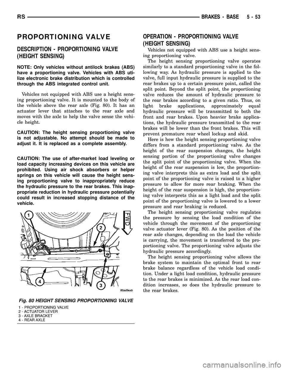
the vehicle above the rear axle (Fig. 80). It has an
actuator lever that attaches to the rear axle and
moves with the axle to help the valve sense the vehi-
cle height.
CAUTION: The height sensing proportioning valve
is not adjustable. No attempt should be made to
adjust it. It is replaced as a complete assembly.
CAUTION: The use of after-market load leveling or
load capacity increasing devices on this vehicle are
prohibited. Using air shock absorbers or helper
springs on this vehicle will cause the height sens-
ing proportioning valve to inappropriately reduce
the hydraulic pressure to the rear brakes. This inap-
propriate reduction in hydraulic pressure potentially
could result in increased stopping distance of the
vehicle.
OPERATION - PROPORTIONING VALVE
(HEIGHT SENSING)
Vehicles not equipped with ABS use a height sens-
ing proportioning valve.
The height sensing proportioning valve operates
similarly to a standard proportioning valve in the fol-
lowing way. As hydraulic pressure is applied to the
valve, full input hydraulic pressure is supplied to the
rear brakes up to a certain pressure point, called the
split point. Beyond the split point, the proportioning
valve reduces the amount of hydraulic pressure to
the rear brakes according to a given ratio. Thus, on
light brake applications, approximately equal
hydraulic pressure will be transmitted to both the
front and rear brakes. Upon heavier brake applica-
tions, the hydraulic pressure transmitted to the rear
brakes will be lower than the front brakes. This will
prevent premature rear wheel lockup and skid.
Here is how the height sensing proportioning valve
differs from a standard proportioning valve. As the
height of the rear suspension changes, the height
sensing portion of the proportioning valve changes
the split point of the proportioning valve. When the
height of the rear suspension is low, the proportion-
ing valve interprets this as extra load and the split
point of the proportioning valve is raised to a higher
pressure to allow for more rear braking. When the
height of the rear suspension is high, the proportion-
ing valve interprets this as a light load and the split
point of the proportioning valve is lowered to a lower
pressure and rear braking is reduced.
The height sensing proportioning valve regulates
the pressure by sensing the load condition of the
vehicle through the movement of the proportioning
valve actuator lever (Fig. 80). As the position of the
rear axle changes, depending on the load the vehicle
is carrying, the movement is transferred to the pro-
portioning valve. The proportioning valve adjusts the
hydraulic pressure accordingly.
The height sensing proportioning valve allows the
brake system to maintain the optimal front to rear
brake balance regardless of the vehicle load condi-
tion. Under a light load condition, hydraulic pressure
to the rear brakes is minimized. As the rear load con-
dition increases, so does the hydraulic pressure to
the rear brakes.
Fig. 80 HEIGHT SENSING PROPORTIONING VALVE
1 - PROPORTIONING VALVE
2 - ACTUATOR LEVER
3 - AXLE BRACKET
4 - REAR AXLE
RSBRAKES - BASE5-53
Page 165 of 2339
DIAGNOSIS AND TESTING - PROPORTIONING
VALVE (HEIGHT SENSING)
CAUTION: The use of aftermarket load leveling or
load capacity increasing devices on this vehicle is
prohibited. Using air shock absorbers or helper
springs on this vehicle will cause the height sens-
ing proportioning valve to inappropriately reduce
the hydraulic pressure to the rear brakes. This inap-
propriate reduction in hydraulic pressure potentially
could result in increased stopping distance of the
vehicle.
When a premature rear wheel skid is obtained on a
brake application, it may be an indication that the
hydraulic pressure to the rear brakes is above the
specified output from the proportioning valve. This
condition indicates a possible malfunction of the
height sensing proportioning valve, which will
require testing to verify that it is properly controlling
the hydraulic pressure allowed to the rear brakes.
Premature rear wheel skid may also be caused by
contaminated front or rear brake linings.
Prior to testing a proportioning valve for function,
check that all tire pressures are correct. Also, ensure
the front and rear brake linings are in satisfactory
condition.It is also necessary to verify that the
brakes shoe assemblies on a vehicle being
tested are either original equipment manufac-
turers (OEM) or original replacement brake
shoe assemblies meeting the OEM lining mate-
rial specification. This vehicles brake system is
not balanced for aftermarket brake shoe assem-
bly lining material.
If both front and rear brakes check OK, proceed
with the following test procedure for the height sens-
ing proportioning valve.
(1) Road test the vehicle to determine which rear
wheel brake is exhibiting premature wheel skid.
(2) Raise vehicle. (Refer to LUBRICATION &
MAINTENANCE/HOISTING - STANDARD PROCE-
DURE)
(3) Remove the chassis brake tube going to the
rear brake in question at the proportioning valve.
Remove the chassis brake tube coming from the junc-
tion block at the proportioning valve (Fig. 81).
(4) Install the appropriate fittings from Pressure
Test Fittings, Special Tool 6833, into the open ports
of the proportioning valve.(5) Install the previously removed brake lines into
the Pressure Test Fittings. Tighten all tube nuts to
17 N´m (145 in. lbs.).
(6) Install a pressure gauge from Gauge Set, Spe-
cial Tool C-4007-A into the open port on each pres-
sure test fitting. Bleed air out of hose from pressure
test fittings to pressure gauges at the pressure
gauges. Then bleed air out of the brake line being
tested at that rear wheel brake bleeder.
NOTE: Actuator rod is a linear spring and is meant
to flex by design. When rod is raised, it will have
some curvature to it.
(7) Remove the screw fastening the proportioning
valve actuator rod bracket to the rear axle. Raise the
actuator lever to the full-upward position and hold it
there.
(8) With the aid of a helper, apply pressure to the
brake pedal until a pressure of 6895 kPa (1000 psi) is
obtained on the proportioning valve inlet gauge.
Then, based on the type of brake system the vehicle
is equipped with and the pressure specification
shown on the following table, compare the pressure
reading on the outlet gauge to the specification. If
outlet pressure at the proportioning valve is not
within specification when required inlet pressure is
obtained, replace the proportioning valve. (Refer to 5
- BRAKES/HYDRAULIC/MECHANICAL/PROPOR-
TIONING VALVE - REMOVAL)
CAUTION: Do not attempt to adjust the height sens-
ing proportioning valve. If found to be defective,
replace the valve.
(9) Remove the pressure test fittings and pressure
gauges from the proportioning valve.
(10) Install the chassis brake lines in the correct
ports of the proportioning valve. Tighten all tube
nuts to 17 N´m (145 in. lbs.).
(11) If necessary, repeat the above steps on the
remaining side of the proportioning valve which con-
trol the other rear wheel brake.
(12) Attach the actuator lever and bracket to the
rear axle.
(13) Bleed rear brakes. (Refer to 5 - BRAKES -
STANDARD PROCEDURE)
(14) Road test vehicle.
5 - 54 BRAKES - BASERS
PROPORTIONING VALVE (Continued)
Page 246 of 2339
INSTALLATION
(1)Be sure the air seal is in position before
radiator is installed.Slide radiator down into posi-
tion. Seat the radiator with the rubber isolators into
the mounting holes provided, with a 10 lbs. force.
(2) Position air conditioning condenser onto the
radiator lower mounts and ingage upper mounting
tabs. (Fig. 15).
(3) Install the radiator upper and lower hoses (Fig.
13) or (Fig. 14).
(4) Connect the coolant reserve/recovery hose.
(5) Connect the vapor purge solenoid to the mount-
ing bracket.
(6) Install the radiator fans. (Refer to 7 - COOL-
ING/ENGINE/RADIATOR FAN - INSTALLATION)
(7) Install the radiator upper crossmember sup-
port. (Refer to 23 - BODY/EXTERIOR/GRILLE
OPENING REINFORCEMENT - INSTALLATION)
(8) Fill the cooling system. (Refer to 7 - COOLING
- STANDARD PROCEDURE)
(9) Connect negative cable to battery.
RADIATOR DRAINCOCK
REMOVAL
NOTE: It is not necessary to remove draincock dur-
ing a routine coolant drain.
(1) Drain the cooling system. (Refer to 7 - COOL-
ING - STANDARD PROCEDURE)
(2) Using a screwdriver, open the draincock by
turning it counterclockwise until it stops.
(3) Pull the draincock from the radiator tank.
INSTALLATION
(1) Align draincock stem to radiator tank opening.
(2) Push draincock into the radiator tank opening.
CAUTION: Do not overtighten. The head of the
draincock may break off.
(3) Using a screwdriver, tighten the draincock by
turning clockwise until it stops.
(4) Fill the cooling system. (Refer to 7 - COOLING
- STANDARD PROCEDURE)
RADIATOR PRESSURE CAP
DESCRIPTION
The cooling system pressure cap is located on the
radiator. The cap construction includes; stainless
steel swivel top, rubber seals, and retainer, main
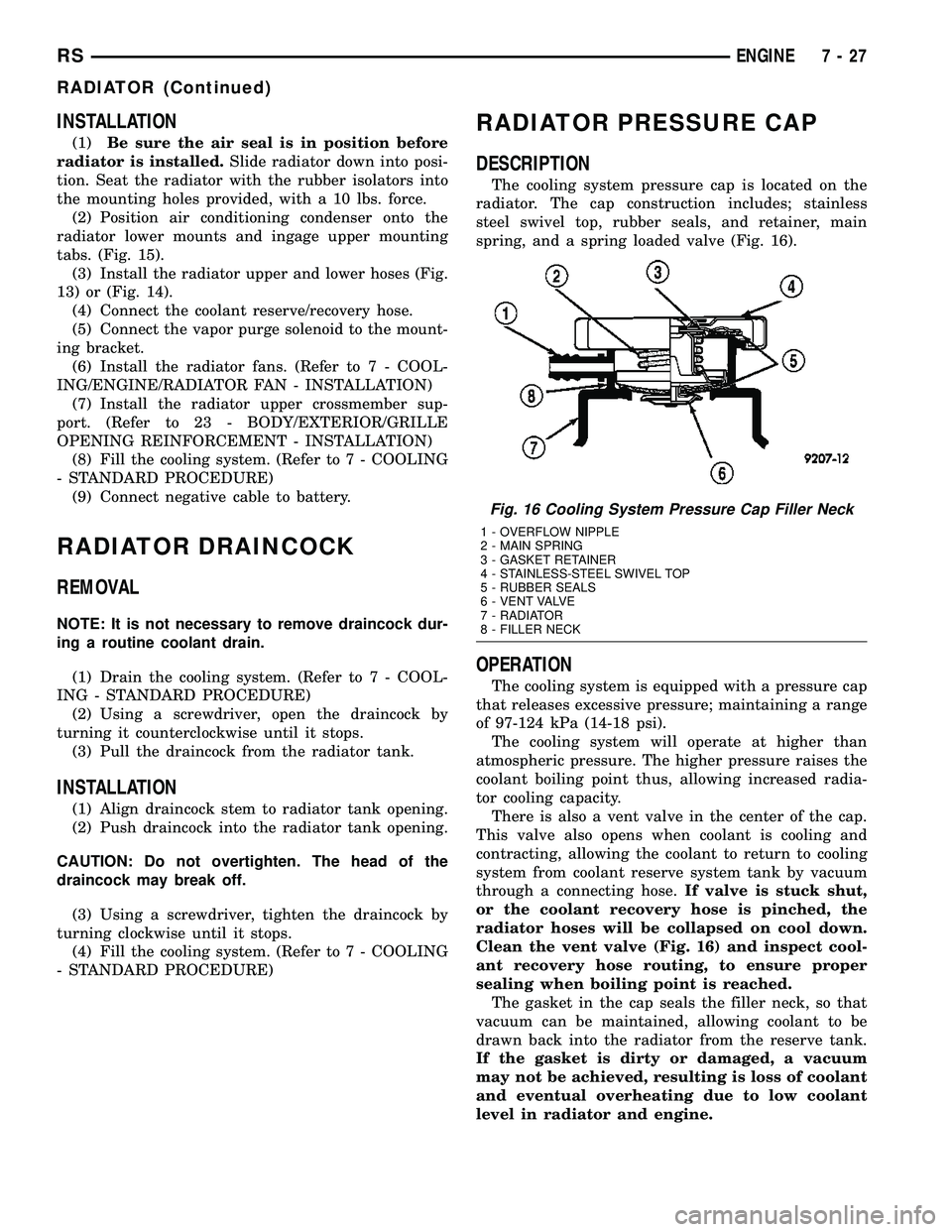
spring, and a spring loaded valve (Fig. 16).
OPERATION
The cooling system is equipped with a pressure cap
that releases excessive pressure; maintaining a range
of 97-124 kPa (14-18 psi).
The cooling system will operate at higher than
atmospheric pressure. The higher pressure raises the
coolant boiling point thus, allowing increased radia-
tor cooling capacity.
There is also a vent valve in the center of the cap.
This valve also opens when coolant is cooling and
contracting, allowing the coolant to return to cooling
system from coolant reserve system tank by vacuum
through a connecting hose.If valve is stuck shut,
or the coolant recovery hose is pinched, the
radiator hoses will be collapsed on cool down.
Clean the vent valve (Fig. 16) and inspect cool-
ant recovery hose routing, to ensure proper
sealing when boiling point is reached.
The gasket in the cap seals the filler neck, so that
vacuum can be maintained, allowing coolant to be
drawn back into the radiator from the reserve tank.
If the gasket is dirty or damaged, a vacuum
may not be achieved, resulting is loss of coolant
and eventual overheating due to low coolant
level in radiator and engine.
Fig. 16 Cooling System Pressure Cap Filler Neck
1 - OVERFLOW NIPPLE
2 - MAIN SPRING
3 - GASKET RETAINER
4 - STAINLESS-STEEL SWIVEL TOP
5 - RUBBER SEALS
6 - VENT VALVE
7 - RADIATOR
8 - FILLER NECK
RSENGINE7-27
RADIATOR (Continued)
Page 311 of 2339
(5) Inspect the battery built-in test indicator sight
glass (if equipped) for an indication of the battery
condition. If the battery is discharged, charge as
required. (Refer to 8 - ELECTRICAL/BATTERY SYS-
TEM/BATTERY - STANDARD PROCEDURE - BAT-
TERY CHARGING) for the proper battery charging
procedures.
SPECIFICATIONS
BATTERY
The battery Group Size number, the Cold Cranking
Amperage (CCA) rating, and the Reserve Capacity(RC) rating or Ampere-Hours (AH) rating can be
found on the original equipment battery label. Be
certain that a replacement battery has the correct
Group Size number, as well as CCA, and RC or AH
ratings that equal or exceed the original equipment
specification for the vehicle being serviced. Battery
sizes and ratings are discussed in more detail below.
²Group Size- The outside dimensions and ter-
minal placement of the battery conform to standards
established by the Battery Council International
(BCI). Each battery is assigned a BCI Group Size
number to help identify a correctly-sized replace-
ment.
²Cold Cranking Amperage- The Cold Crank-
ing Amperage (CCA) rating specifies how much cur-
rent (in amperes) the battery can deliver for thirty
seconds at -18É C (0É F). Terminal voltage must not
fall below 7.2 volts during or after the thirty second
discharge period. The CCA required is generally
higher as engine displacement increases, depending
also upon the starter current draw requirements.
²Reserve Capacity- The Reserve Capacity (RC)
rating specifies the time (in minutes) it takes for bat-
tery terminal voltage to fall below 10.5 volts, at a
discharge rate of 25 amperes. RC is determined with
the battery fully-charged at 26.7É C (80É F). This rat-
ing estimates how long the battery might last after a
charging system failure, under minimum electrical
load.
²Ampere-Hours- The Ampere-Hours (AH) rat-
ing specifies the current (in amperes) that a battery
can deliver steadily for twenty hours, with the volt-
age in the battery not falling below 10.5 volts. This
rating is also sometimes identified as the twenty-
hour discharge rating.
BATTERY CLASSIFICATIONS & RATINGS
Part NumberBCI Group Size
ClassificationCold Cranking
AmperageReserve
CapacityAmpere -
HoursLoad Test
Amperage
4686158AD 34 500 110 Minutes 60 250
4727159AD 34 600 120 Minutes 66 300
4727242AD DIN H6 600 120 Minutes 66 300
4868999AA 34 700 90 Minutes 50 350
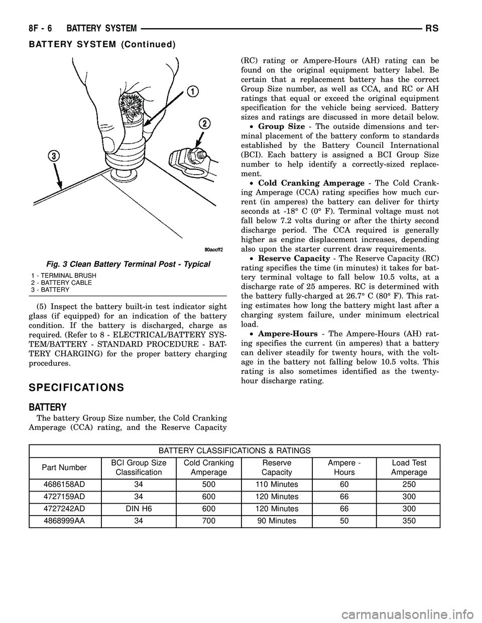
Fig. 3 Clean Battery Terminal Post - Typical
1 - TERMINAL BRUSH
2 - BATTERY CABLE
3 - BATTERY
8F - 6 BATTERY SYSTEMRS
BATTERY SYSTEM (Continued)
Page 314 of 2339
battery for a low electrolyte condition and before
returning the vehicle to service. (Refer to 8 - ELEC-
TRICAL/CHARGING - DIAGNOSIS AND TESTING)
for additional information.
The battery Group Size number, the Cold Cranking
Amperage (CCA) rating, and the Reserve Capacity
(RC) rating or Ampere-Hours (AH) rating can be
found on the original equipment battery label. Be
certain that a replacement battery has the correct
Group Size number, as well as CCA, and RC or AH
ratings that equal or exceed the original equipment
specification for the vehicle being serviced. (Refer to
8 - ELECTRICAL/BATTERY SYSTEM - SPECIFICA-
TIONS) for the proper factory-installed battery spec-
ifications.
OPERATION
The battery is designed to store electrical energy in
a chemical form. When an electrical load is applied to
the terminals of the battery, an electrochemical reac-
tion occurs. This reaction causes the battery to dis-
charge electrical current from its terminals. As the
battery discharges, a gradual chemical change takes
place within each cell. The sulfuric acid in the elec-
trolyte combines with the plate materials, causing
both plates to slowly change to lead sulfate. At the
same time, oxygen from the positive plate material
combines with hydrogen from the sulfuric acid, caus-
ing the electrolyte to become mainly water. The
chemical changes within the battery are caused by
the movement of excess or free electrons between the
positive and negative plate groups. This movement of
electrons produces a flow of electrical current
through the load device attached to the battery ter-
minals.
As the plate materials become more similar chem-
ically, and the electrolyte becomes less acid, the volt-
age potential of each cell is reduced. However, by
charging the battery with a voltage higher than that
of the battery itself, the battery discharging process
is reversed. Charging the battery gradually changes
the sulfated lead plates back into sponge lead and
lead dioxide, and the water back into sulfuric acid.
This action restores the difference in the electron
charges deposited on the plates, and the voltage
potential of the battery cells. For a battery to remain
useful, it must be able to produce high-amperage cur-
rent over an extended period. A battery must also be
able to accept a charge, so that its voltage potential
may be restored.
The battery is vented to release excess hydrogen
gas that is created when the battery is being charged
or discharged. However, even with these vents,
hydrogen gas can collect in or around the battery. If
hydrogen gas is exposed to flame or sparks, it may
ignite. If the electrolyte level is low, the battery mayarc internally and explode. If the battery is equipped
with removable cell caps, add distilled water when-
ever the electrolyte level is below the top of the
plates. If the battery cell caps cannot be removed, the
battery must be replaced if the electrolyte level
becomes low.
DIAGNOSIS AND TESTING
BATTERY
The battery must be completely charged and the
terminals should be properly cleaned and inspected
before diagnostic procedures are performed. (Refer to
8 - ELECTRICAL/BATTERY SYSTEM - CLEANING)
for the proper cleaning procedures, and (Refer to 8 -
ELECTRICAL/BATTERY SYSTEM - INSPECTION)
for the proper battery inspection procedures. (Refer
to 8 - ELECTRICAL/BATTERY SYSTEM/BATTERY -
STANDARD PROCEDURE) for the proper battery
charging procedures.
MICRO 420 BATTERY TESTER
The Micro 420 automotive battery tester is
designed to help the dealership technicians diagnose
the cause of a defective battery. Follow the instruc-
tion manual supplied with the tester or (Refer to 8 -
ELECTRICAL/BATTERY SYSTEM/BATTERY -
STANDARD PROCEDURE - USING THE MICRO
420 BATTERY TESTER) to properly diagnose a vehi-
cle
WARNING: IF THE BATTERY SHOWS SIGNS OF
FREEZING, LEAKING OR LOOSE POSTS, DO NOT
TEST, ASSIST-BOOST, OR CHARGE. THE BATTERY
MAY ARC INTERNALLY AND EXPLODE. PERSONAL
INJURY AND/OR VEHICLE DAMAGE MAY RESULT.
WARNING: EXPLOSIVE HYDROGEN GAS FORMS IN
AND AROUND THE BATTERY. DO NOT SMOKE,
USE FLAME, OR CREATE SPARKS NEAR THE BAT-
TERY. PERSONAL INJURY AND/OR VEHICLE DAM-
AGE MAY RESULT.
WARNING: THE BATTERY CONTAINS SULFURIC
ACID, WHICH IS POISONOUS AND CAUSTIC. AVOID
CONTACT WITH THE SKIN, EYES, OR CLOTHING.
IN THE EVENT OF CONTACT, FLUSH WITH WATER
AND CALL A PHYSICIAN IMMEDIATELY. KEEP OUT
OF THE REACH OF CHILDREN.
A battery that will not accept a charge is inopera-
tive, and must be replaced. Further testing is not
required. A fully-charged battery must be tested to
determine its cranking capacity. A battery that is ful-
RSBATTERY SYSTEM8F-9
BATTERY (Continued)
Page 315 of 2339
ly-charged, but does not pass the Micro 420 or load
test, is inoperative and must be replaced.
NOTE: Completely discharged batteries may take
several hours to accept a charge. (Refer to 8 -
ELECTRICAL/BATTERY SYSTEM/BATTERY - STAN-
DARD PROCEDURE) for the proper battery charging
procedures.
STANDARD PROCEDURE
SPIRAL PLATE BATTERY CHARGING
Vehicles equipped with a diesel engine utilize a
unique spiral plate battery. This battery has a maxi-
mum charging voltage that must not be exceeded in
order to restore the battery to its full potential, fail-
ure to use the following spiral plate battery charging
procedure could result in damage to the battery or
personal injury.
Battery charging is the means by which the bat-
tery can be restored to its full voltage potential. A
battery is fully-charged when:
²Micro 420 battery tester indicates battery is OK.
²Open-circuit voltage of the battery is 12.65 volts
or above.
²Battery passes Load Test multiple times.
WARNING: IF THE BATTERY SHOWS SIGNS OF
FREEZING, LEAKING, LOOSE POSTS OR LOW
ELECTROLYTE LEVEL, DO NOT TEST, ASSIST-
BOOST, OR CHARGE. THE BATTERY MAY ARC
INTERNALLY AND EXPLODE. PERSONAL INJURY
AND/OR VEHICLE DAMAGE MAY RESULT.
CAUTION: Always disconnect and isolate the bat-
tery negative cable before charging a battery.
Charge the battery directly at the battery terminals.
Do not exceed 14.4 volts while charging a battery.
CAUTION: The battery should not be hot to the
touch. If the battery feels hot to the touch, turn off
the charger and let the battery cool before continu-
ing the charging operation. Damage to the battery
may result.
After the battery has been charged to 12.6 volts or
greater, perform a load test to determine the battery
cranking capacity. (Refer to 8 - ELECTRICAL/BAT-
TERY SYSTEM/BATTERY - STANDARD PROCE-
DURE - USING THE MICRO 420 BATTERY
TESTER) for the proper battery test procedures. If
the battery passes a load test, return the battery to
service. If the battery will not pass a load test, it is
inoperative and must be replaced.Clean and inspect the battery hold downs, tray,
terminals, posts, and top before completing battery
service. (Refer to 8 - ELECTRICAL/BATTERY SYS-
TEM - CLEANING) for the proper battery system
cleaning procedures, and (Refer to 8 - ELECTRICAL/
BATTERY SYSTEM - INSPECTION) for the proper
battery system inspection procedures.
CHARGING A COMPLETELY DISCHARGED
BATTERY ± SPIRAL PLATE BATTERY
The following procedure should be used to recharge
a completely discharged battery. Unless this proce-
dure is properly followed, a good battery may be
needlessly replaced.
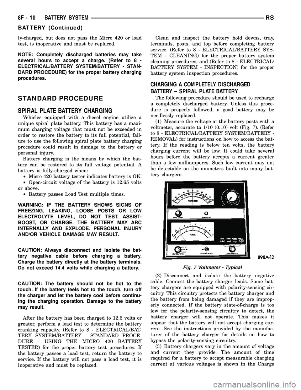
(1) Measure the voltage at the battery posts with a
voltmeter, accurate to 1/10 (0.10) volt (Fig. 7). (Refer
to 8 - ELECTRICAL/BATTERY SYSTEM/BATTERY -
REMOVAL) for instructions on how to access the bat-
tery. If the reading is below ten volts, the battery
charging current will be low. It could take several
hours before the battery accepts a current greater
than a few milliamperes. Such low current may not
be detectable on the ammeters built into many bat-
tery chargers.
(2) Disconnect and isolate the battery negative
cable. Connect the battery charger leads. Some bat-
tery chargers are equipped with polarity-sensing cir-
cuitry. This circuitry protects the battery charger and
the battery from being damaged if they are improp-
erly connected. If the battery state-of-charge is too
low for the polarity-sensing circuitry to detect, the
battery charger will not operate. This makes it
appear that the battery will not accept charging cur-
rent. See the instructions provided by the manufac-
turer of the battery charger for details on how to
bypass the polarity-sensing circuitry.
(3) Battery chargers vary in the amount of voltage
and current they provide. The amount of time
required for a battery to accept measurable charging
current at various voltages is shown in the Charge
Fig. 7 Voltmeter - Typical
8F - 10 BATTERY SYSTEMRS
BATTERY (Continued)
Page 316 of 2339
Rate Table. If the charging current is still not mea-
surable at the end of the charging time, the battery
is inoperative and must be replaced. If the charging
current is measurable during the charging time, the
battery may be good and the charging should be com-
pleted in the normal manner.
SPIRAL-PLATE BATTERY CHARGE RATE TABLE
Voltage Minutes
14.4 volts maximum up to 10 minutes
13.0 to 14 volts up to 20 minutes
12.9 volts or less up to 30 minutes
CHARGING TIME REQUIRED
The time required to charge a battery will vary,
depending upon the following factors:
²Battery Capacity- A completely discharged
heavy-duty battery requires twice the charging time
of a small capacity battery.
²Temperature- A longer time will be needed to
charge a battery at -18É C (0É F) than at 27É C (80É
F). When a fast battery charger is connected to a cold
battery, the current accepted by the battery will be
very low at first. As the battery warms, it will accept
a higher charging current rate (amperage).
²Charger Capacity- A battery charger that
supplies only five amperes will require a longer
charging time. A battery charger that supplies eight
amperes will require a shorter charging time.
²State-Of-Charge- A completely discharged bat-
tery requires more charging time than a partially
discharged battery. Electrolyte is nearly pure water
in a completely discharged battery. At first, the
charging current (amperage) will be low. As the bat-
tery charges, the specific gravity of the electrolyte
will gradually rise.
The Battery Charging Time Table gives an indica-
tion of the time required to charge a typical battery
at room temperature based upon the battery state-of-
charge and the charger capacity.
SPIRAL-PLATE BATTERY CHARGING TIME
TABLE
Charging
Amperage5 Amps 8 Amps
Open Circuit
VoltageHours Charging @ 21É
C (70É F)
12.25 to 12.49 6 hours 3 hours
12.00 to 12.24 10 hours 5 hours
10.00 to 11.99 14 hours 7 hours
Below 10.00 18 hours 9 hours
CONVENTIONAL BATTERY CHARGING
Vehicles equipped with a diesel engine utilize a
unique spiral plate battery. This battery has a maxi-
mum charging voltage that must be used in order to
restore the battery to its full potential, failure to use
the spiral plate battery charging procedure could
result in damage to the battery or personal injury.
Battery charging is the means by which the bat-
tery can be restored to its full voltage potential. A
battery is fully-charged when:
²Micro 420 battery tester indicates battery is OK.
²Open-circuit voltage of the battery is 12.65 volts
or above.
²Battery passes Load Test multiple times.
WARNING: IF THE BATTERY SHOWS SIGNS OF
FREEZING, LEAKING, LOOSE POSTS, DO NOT
TEST, ASSIST-BOOST, OR CHARGE. THE BATTERY
MAY ARC INTERNALLY AND EXPLODE. PERSONAL
INJURY AND/OR VEHICLE DAMAGE MAY RESULT.
WARNING: EXPLOSIVE HYDROGEN GAS FORMS IN
AND AROUND THE BATTERY. DO NOT SMOKE,
USE FLAME, OR CREATE SPARKS NEAR THE BAT-
TERY. PERSONAL INJURY AND/OR VEHICLE DAM-
AGE MAY RESULT.
WARNING: THE BATTERY CONTAINS SULFURIC
ACID, WHICH IS POISONOUS AND CAUSTIC. AVOID
CONTACT WITH THE SKIN, EYES, OR CLOTHING.
IN THE EVENT OF CONTACT, FLUSH WITH WATER
AND CALL A PHYSICIAN IMMEDIATELY. KEEP OUT
OF THE REACH OF CHILDREN.
WARNING: IF THE BATTERY IS EQUIPPED WITH
REMOVABLE CELL CAPS, BE CERTAIN THAT EACH
OF THE CELL CAPS IS IN PLACE AND TIGHT
BEFORE THE BATTERY IS RETURNED TO SER-
VICE. PERSONAL INJURY AND/OR VEHICLE DAM-
AGE MAY RESULT FROM LOOSE OR MISSING
CELL CAPS.
CAUTION: Always disconnect and isolate the bat-
tery negative cable before charging a battery. Do
not exceed sixteen volts while charging a battery.
Damage to the vehicle electrical system compo-
nents may result.
RSBATTERY SYSTEM8F-11
BATTERY (Continued)
Page 317 of 2339
CAUTION: Battery electrolyte will bubble inside the
battery case during normal battery charging. Elec-
trolyte boiling or being discharged from the battery
vents indicates a battery overcharging condition.
Immediately reduce the charging rate or turn off the
charger to evaluate the battery condition. Damage
to the battery may result from overcharging.
CAUTION: The battery should not be hot to the
touch. If the battery feels hot to the touch, turn off
the charger and let the battery cool before continu-
ing the charging operation. Damage to the battery
may result.
After the battery has been charged to an open-cir-
cuit voltage reading of 12.4 volts or greater, retest
the battery with the Micro 420 tester or perform a
load test to determine the battery cranking capacity.
(Refer to 8 - ELECTRICAL/BATTERY SYSTEM/BAT-
TERY - STANDARD PROCEDURE) for the proper
battery load test procedures. If the battery passes a
load test, return the battery to service. If the battery
will not pass a load test, it is inoperative and must
be replaced.
Clean and inspect the battery hold downs, tray,
terminals, posts, and top before completing battery
service. (Refer to 8 - ELECTRICAL/BATTERY SYS-
TEM - CLEANING) for the proper battery system
cleaning procedures, and (Refer to 8 - ELECTRICAL/
BATTERY SYSTEM - INSPECTION) for the proper
battery system inspection procedures.
CHARGING A COMPLETELY DISCHARGED
CONVENTIONAL BATTERY
The following procedure should be used to recharge
a completely discharged battery. Unless this proce-
dure is properly followed, a good battery may be
needlessly replaced.
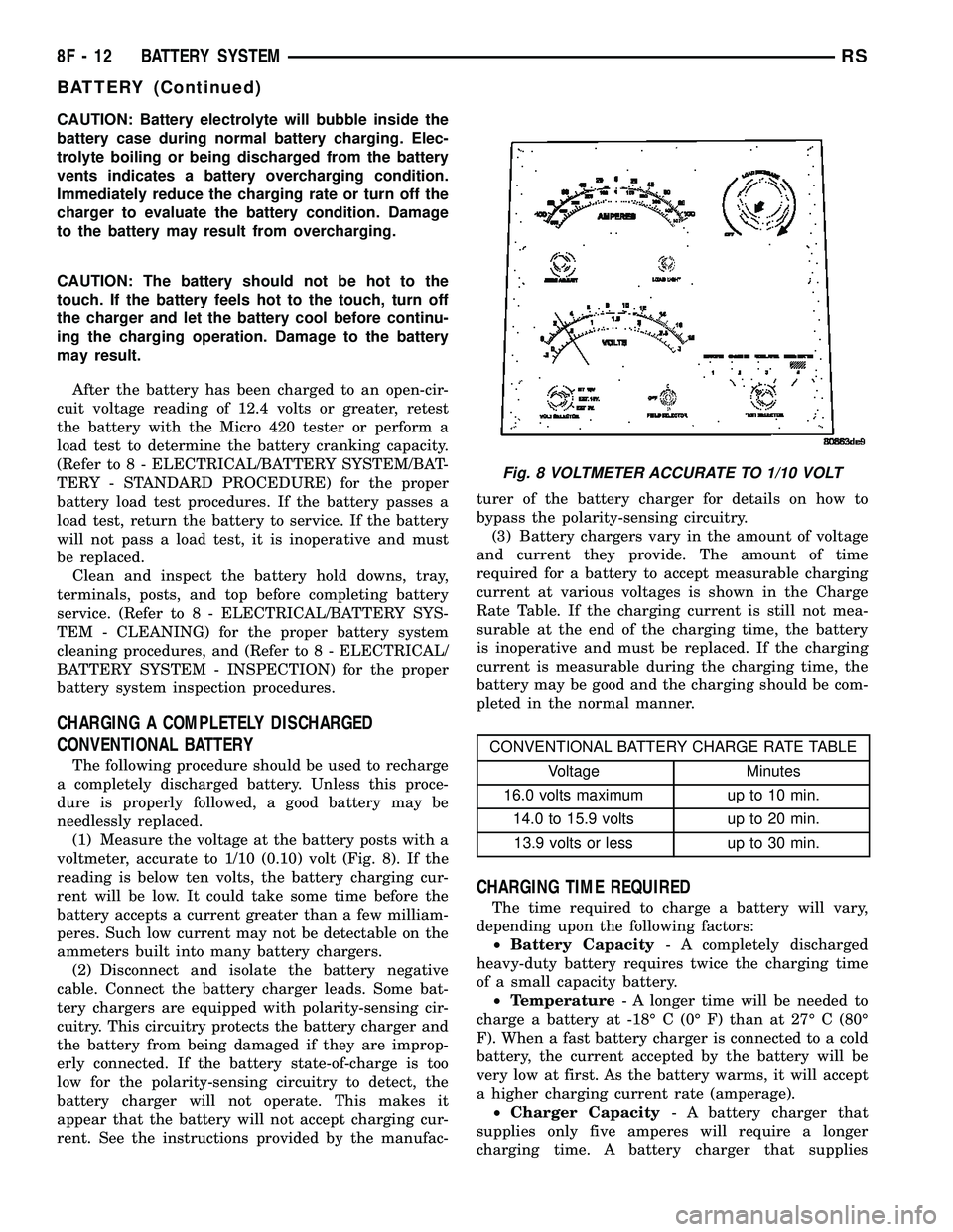
(1) Measure the voltage at the battery posts with a
voltmeter, accurate to 1/10 (0.10) volt (Fig. 8). If the
reading is below ten volts, the battery charging cur-
rent will be low. It could take some time before the
battery accepts a current greater than a few milliam-
peres. Such low current may not be detectable on the
ammeters built into many battery chargers.
(2) Disconnect and isolate the battery negative
cable. Connect the battery charger leads. Some bat-
tery chargers are equipped with polarity-sensing cir-
cuitry. This circuitry protects the battery charger and
the battery from being damaged if they are improp-
erly connected. If the battery state-of-charge is too
low for the polarity-sensing circuitry to detect, the
battery charger will not operate. This makes it
appear that the battery will not accept charging cur-
rent. See the instructions provided by the manufac-turer of the battery charger for details on how to
bypass the polarity-sensing circuitry.
(3) Battery chargers vary in the amount of voltage
and current they provide. The amount of time
required for a battery to accept measurable charging
current at various voltages is shown in the Charge
Rate Table. If the charging current is still not mea-
surable at the end of the charging time, the battery
is inoperative and must be replaced. If the charging
current is measurable during the charging time, the
battery may be good and the charging should be com-
pleted in the normal manner.
CONVENTIONAL BATTERY CHARGE RATE TABLE
Voltage Minutes
16.0 volts maximum up to 10 min.
14.0 to 15.9 volts up to 20 min.
13.9 volts or less up to 30 min.
CHARGING TIME REQUIRED
The time required to charge a battery will vary,
depending upon the following factors:
²Battery Capacity- A completely discharged
heavy-duty battery requires twice the charging time
of a small capacity battery.
²Temperature- A longer time will be needed to
charge a battery at -18É C (0É F) than at 27É C (80É
F). When a fast battery charger is connected to a cold
battery, the current accepted by the battery will be
very low at first. As the battery warms, it will accept
a higher charging current rate (amperage).
²Charger Capacity- A battery charger that
supplies only five amperes will require a longer
charging time. A battery charger that supplies
Fig. 8 VOLTMETER ACCURATE TO 1/10 VOLT
8F - 12 BATTERY SYSTEMRS
BATTERY (Continued)
Page 318 of 2339
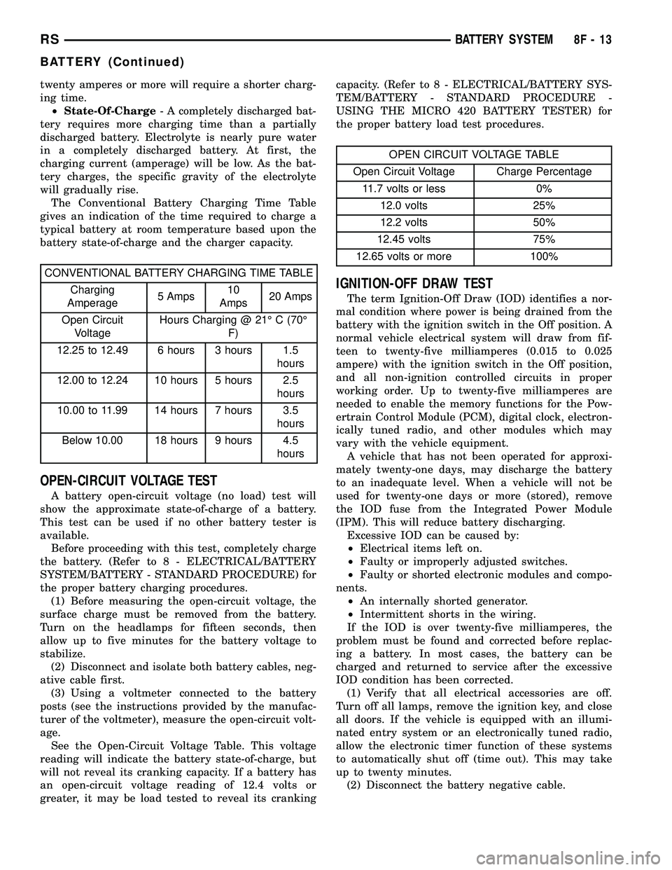
twenty amperes or more will require a shorter charg-
ing time.
²State-Of-Charge- A completely discharged bat-
tery requires more charging time than a partially
discharged battery. Electrolyte is nearly pure water
in a completely discharged battery. At first, the
charging current (amperage) will be low. As the bat-
tery charges, the specific gravity of the electrolyte
will gradually rise.
The Conventional Battery Charging Time Table
gives an indication of the time required to charge a
typical battery at room temperature based upon the
battery state-of-charge and the charger capacity.
CONVENTIONAL BATTERY CHARGING TIME TABLE
Charging
Amperage5 Amps10
Amps20 Amps
Open Circuit
VoltageHours Charging @ 21É C (70É
F)
12.25 to 12.49 6 hours 3 hours 1.5
hours
12.00 to 12.24 10 hours 5 hours 2.5
hours
10.00 to 11.99 14 hours 7 hours 3.5
hours
Below 10.00 18 hours 9 hours 4.5
hours
OPEN-CIRCUIT VOLTAGE TEST
A battery open-circuit voltage (no load) test will
show the approximate state-of-charge of a battery.
This test can be used if no other battery tester is
available.
Before proceeding with this test, completely charge
the battery. (Refer to 8 - ELECTRICAL/BATTERY
SYSTEM/BATTERY - STANDARD PROCEDURE) for
the proper battery charging procedures.
(1) Before measuring the open-circuit voltage, the
surface charge must be removed from the battery.
Turn on the headlamps for fifteen seconds, then
allow up to five minutes for the battery voltage to
stabilize.
(2) Disconnect and isolate both battery cables, neg-
ative cable first.
(3) Using a voltmeter connected to the battery
posts (see the instructions provided by the manufac-
turer of the voltmeter), measure the open-circuit volt-
age.
See the Open-Circuit Voltage Table. This voltage
reading will indicate the battery state-of-charge, but
will not reveal its cranking capacity. If a battery has
an open-circuit voltage reading of 12.4 volts or
greater, it may be load tested to reveal its crankingcapacity. (Refer to 8 - ELECTRICAL/BATTERY SYS-
TEM/BATTERY - STANDARD PROCEDURE -
USING THE MICRO 420 BATTERY TESTER) for
the proper battery load test procedures.
OPEN CIRCUIT VOLTAGE TABLE
Open Circuit Voltage Charge Percentage
11.7 volts or less 0%
12.0 volts 25%
12.2 volts 50%
12.45 volts 75%
12.65 volts or more 100%
IGNITION-OFF DRAW TEST
The term Ignition-Off Draw (IOD) identifies a nor-
mal condition where power is being drained from the
battery with the ignition switch in the Off position. A
normal vehicle electrical system will draw from fif-
teen to twenty-five milliamperes (0.015 to 0.025
ampere) with the ignition switch in the Off position,
and all non-ignition controlled circuits in proper
working order. Up to twenty-five milliamperes are
needed to enable the memory functions for the Pow-
ertrain Control Module (PCM), digital clock, electron-
ically tuned radio, and other modules which may
vary with the vehicle equipment.
A vehicle that has not been operated for approxi-
mately twenty-one days, may discharge the battery
to an inadequate level. When a vehicle will not be
used for twenty-one days or more (stored), remove
the IOD fuse from the Integrated Power Module
(IPM). This will reduce battery discharging.
Excessive IOD can be caused by:
²Electrical items left on.
²Faulty or improperly adjusted switches.
²Faulty or shorted electronic modules and compo-
nents.
²An internally shorted generator.
²Intermittent shorts in the wiring.
If the IOD is over twenty-five milliamperes, the
problem must be found and corrected before replac-
ing a battery. In most cases, the battery can be
charged and returned to service after the excessive
IOD condition has been corrected.
(1) Verify that all electrical accessories are off.
Turn off all lamps, remove the ignition key, and close
all doors. If the vehicle is equipped with an illumi-
nated entry system or an electronically tuned radio,
allow the electronic timer function of these systems
to automatically shut off (time out). This may take
up to twenty minutes.
(2) Disconnect the battery negative cable.
RSBATTERY SYSTEM8F-13
BATTERY (Continued)
Page 336 of 2339
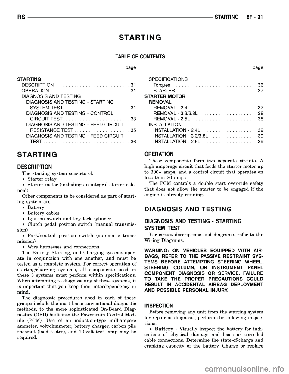
STARTING
TABLE OF CONTENTS
page page
STARTING
DESCRIPTION.........................31
OPERATION...........................31
DIAGNOSIS AND TESTING
DIAGNOSIS AND TESTING - STARTING
SYSTEM TEST.......................31
DIAGNOSIS AND TESTING - CONTROL
CIRCUIT TEST........................33
DIAGNOSIS AND TESTING - FEED CIRCUIT
RESISTANCE TEST....................35
DIAGNOSIS AND TESTING - FEED CIRCUIT
TEST...............................36SPECIFICATIONS
Torques.............................36
STARTER ...........................37
STARTER MOTOR
REMOVAL
REMOVAL - 2.4L......................37
REMOVAL - 3.3/3.8L...................38
REMOVAL - 2.5L......................38
INSTALLATION
INSTALLATION - 2.4L..................39
INSTALLATION - 3.3/3.8L................39
INSTALLATION - 2.5L..................39
STARTING
DESCRIPTION
The starting system consists of:
²Starter relay
²Starter motor (including an integral starter sole-
noid)
Other components to be considered as part of start-
ing system are:
²Battery
²Battery cables
²Ignition switch and key lock cylinder
²Clutch pedal position switch (manual transmis-
sion)
²Park/neutral position switch (automatic trans-
mission)
²Wire harnesses and connections.
The Battery, Starting, and Charging systems oper-
ate in conjunction with one another, and must be
tested as a complete system. For correct operation of
starting/charging systems, all components used in
these 3 systems must perform within specifications.
When attempting to diagnose any of these systems, it
is important that you keep their interdependency in
mind.
The diagnostic procedures used in each of these
groups include the most basic conventional diagnostic
methods, to the more sophisticated On-Board Diag-
nostics (OBD) built into the Powertrain Control Mod-
ule (PCM). Use of an induction-type milliampere
ammeter, volt/ohmmeter, battery charger, carbon pile
rheostat (load tester), and 12-volt test lamp may be
required.
OPERATION
These components form two separate circuits. A
high amperage circuit that feeds the starter motor up
to 300+ amps, and a control circuit that operates on
less than 20 amps.
The PCM controls a double start over-ride safety
that does not allow the starter to be engaged if the
engine is already running.
DIAGNOSIS AND TESTING
DIAGNOSIS AND TESTING - STARTING
SYSTEM TEST
For circuit descriptions and diagrams, refer to the
Wiring Diagrams.
WARNING: ON VEHICLES EQUIPPED WITH AIR-
BAGS, REFER TO THE PASSIVE RESTRAINT SYS-
TEMS BEFORE ATTEMPTING STEERING WHEEL,
STEERING COLUMN, OR INSTRUMENT PANEL
COMPONENT DIAGNOSIS OR SERVICE. FAILURE
TO TAKE THE PROPER PRECAUTIONS COULD
RESULT IN ACCIDENTAL AIRBAG DEPLOYMENT
AND POSSIBLE PERSONAL INJURY.
INSPECTION
Before removing any unit from the starting system
for repair or diagnosis, perform the following inspec-
tions:
²Battery- Visually inspect the battery for indi-
cations of physical damage and loose or corroded
cable connections. Determine the state-of-charge and
cranking capacity of the battery. Charge or replace
RSSTARTING8F-31