airbag off CHRYSLER CARAVAN 2005 Service Manual
[x] Cancel search | Manufacturer: CHRYSLER, Model Year: 2005, Model line: CARAVAN, Model: CHRYSLER CARAVAN 2005Pages: 2339, PDF Size: 59.69 MB
Page 261 of 2339
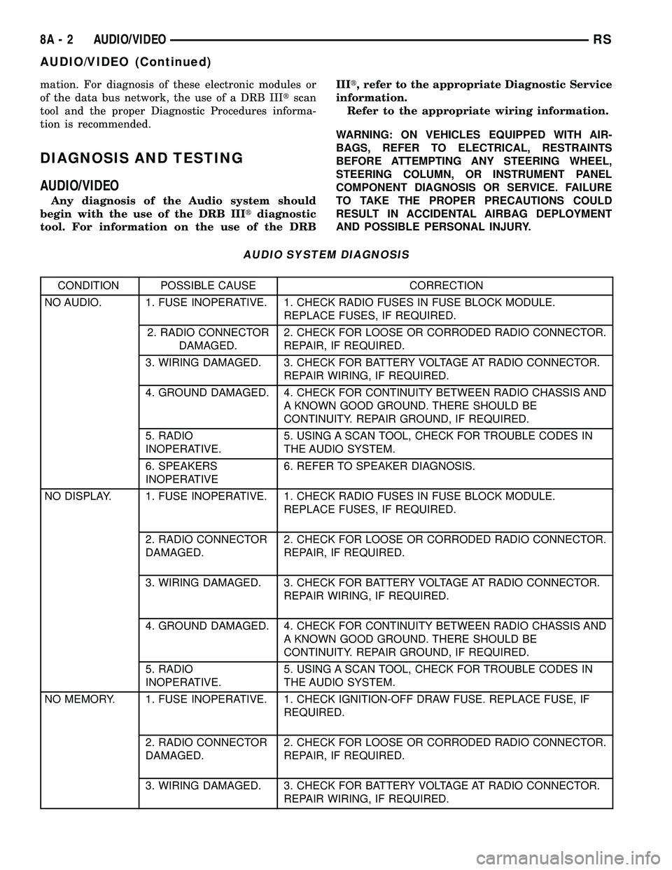
mation. For diagnosis of these electronic modules or
of the data bus network, the use of a DRB IIItscan
tool and the proper Diagnostic Procedures informa-
tion is recommended.
DIAGNOSIS AND TESTING
AUDIO/VIDEO
Any diagnosis of the Audio system should
begin with the use of the DRB IIItdiagnostic
tool. For information on the use of the DRBIIIt, refer to the appropriate Diagnostic Service
information.
Refer to the appropriate wiring information.
WARNING: ON VEHICLES EQUIPPED WITH AIR-
BAGS, REFER TO ELECTRICAL, RESTRAINTS
BEFORE ATTEMPTING ANY STEERING WHEEL,
STEERING COLUMN, OR INSTRUMENT PANEL
COMPONENT DIAGNOSIS OR SERVICE. FAILURE
TO TAKE THE PROPER PRECAUTIONS COULD
RESULT IN ACCIDENTAL AIRBAG DEPLOYMENT
AND POSSIBLE PERSONAL INJURY.
AUDIO SYSTEM DIAGNOSIS
CONDITION POSSIBLE CAUSE CORRECTION
NO AUDIO. 1. FUSE INOPERATIVE. 1. CHECK RADIO FUSES IN FUSE BLOCK MODULE.
REPLACE FUSES, IF REQUIRED.
2. RADIO CONNECTOR
DAMAGED.2. CHECK FOR LOOSE OR CORRODED RADIO CONNECTOR.
REPAIR, IF REQUIRED.
3. WIRING DAMAGED. 3. CHECK FOR BATTERY VOLTAGE AT RADIO CONNECTOR.
REPAIR WIRING, IF REQUIRED.
4. GROUND DAMAGED. 4. CHECK FOR CONTINUITY BETWEEN RADIO CHASSIS AND
A KNOWN GOOD GROUND. THERE SHOULD BE
CONTINUITY. REPAIR GROUND, IF REQUIRED.
5. RADIO
INOPERATIVE.5. USING A SCAN TOOL, CHECK FOR TROUBLE CODES IN
THE AUDIO SYSTEM.
6. SPEAKERS
INOPERATIVE6. REFER TO SPEAKER DIAGNOSIS.
NO DISPLAY. 1. FUSE INOPERATIVE. 1. CHECK RADIO FUSES IN FUSE BLOCK MODULE.
REPLACE FUSES, IF REQUIRED.
2. RADIO CONNECTOR
DAMAGED.2. CHECK FOR LOOSE OR CORRODED RADIO CONNECTOR.
REPAIR, IF REQUIRED.
3. WIRING DAMAGED. 3. CHECK FOR BATTERY VOLTAGE AT RADIO CONNECTOR.
REPAIR WIRING, IF REQUIRED.
4. GROUND DAMAGED. 4. CHECK FOR CONTINUITY BETWEEN RADIO CHASSIS AND
A KNOWN GOOD GROUND. THERE SHOULD BE
CONTINUITY. REPAIR GROUND, IF REQUIRED.
5. RADIO
INOPERATIVE.5. USING A SCAN TOOL, CHECK FOR TROUBLE CODES IN
THE AUDIO SYSTEM.
NO MEMORY. 1. FUSE INOPERATIVE. 1. CHECK IGNITION-OFF DRAW FUSE. REPLACE FUSE, IF
REQUIRED.
2. RADIO CONNECTOR
DAMAGED.2. CHECK FOR LOOSE OR CORRODED RADIO CONNECTOR.
REPAIR, IF REQUIRED.
3. WIRING DAMAGED. 3. CHECK FOR BATTERY VOLTAGE AT RADIO CONNECTOR.
REPAIR WIRING, IF REQUIRED.
8A - 2 AUDIO/VIDEORS
AUDIO/VIDEO (Continued)
Page 273 of 2339
OPERATION
The radio receiver operates on ignition switched
battery current that is available only when the igni-
tion switch is in the On or Accessory/Accessory Delay
positions. The electronic digital clock function of the
radio operates on fused battery current supplied
through the IOD fuse, regardless of the ignition
switch position.
For complete circuit diagrams, refer to the appro-
priate wiring information.
DIAGNOSIS AND TESTING
RADIO
WARNING: ON VEHICLES EQUIPPED WITH AIR-
BAGS, REFER TO ELECTRICAL, RESTRAINTS
BEFORE ATTEMPTING ANY STEERING WHEEL,
STEERING COLUMN, OR INSTRUMENT PANEL
COMPONENT DIAGNOSIS OR SERVICE. FAILURE
TO TAKE THE PROPER PRECAUTIONS COULD
RESULT IN ACCIDENTAL AIRBAG DEPLOYMENT
AND POSSIBLE PERSONAL INJURY.
Any diagnosis of the Audio system should
begin with the use of the DRB IIItdiagnostic
tool. For information on the use of the DRB
IIIt, refer to the appropriate Diagnostic Service
Manual.
Refer to the appropriate wiring information.
If the vehicle is equipped with remote radio
switches located on the back of the steering wheel
spokes, and the problem being diagnosed is related to
one of the symptoms listed below, be certain to check
the remote radio switches and circuits as described
in this group, prior to attempting radio diagnosis or
repair.
²Stations changing with no remote radio switch
input
²Radio memory presets not working properly
²Volume changes with no remote radio switch
input
²Remote radio switch buttons taking on other
functions
²CD player skipping tracks
²Remote radio switch inoperative.
CAUTION: The speaker output of the radio is a
ªfloating groundº system. Do not allow any speaker
lead to short to ground, as damage to the radio
may result.
(1) Check the fuse(s) in the junction block and the
Integrated Power Module (IPM). If OK, go to Step 2.
If not OK, repair the shorted circuit or component as
required and replace the faulty fuse(s).(2) Check for battery voltage at the fuse in the
(IPM). If OK, go to Step 3. If not OK, repair the open
circuit to the battery as required.
(3) Turn the ignition switch to the ON position.
Check for battery voltage at the fuse in the junction
block. If OK, go to Step 4. If not OK, repair the open
circuit to the ignition switch as required.
(4) Turn the ignition switch to the OFF position.
Remove the radio, but do not unplug the wire har-
ness connectors. Check for continuity between the
radio chassis and a good ground. There should be
continuity. If OK, go to Step 5. If not OK, repair the
open radio chassis ground circuit as required.
(5) Connect the battery negative cable. Turn the
ignition switch to the ON position. Check for battery
voltage at the fused ignition switch output circuit
cavity of the radio wire harness connector. If OK, go
to Step 6. If not OK, repair the open circuit as
required.
(6) Turn the ignition switch to the OFF position.
Check for battery voltage at the fused B(+) circuit
cavity of the radio wire harness connector. If OK,
replace the faulty radio. If not OK, repair the open
circuit to the Ignition-Off Draw (IOD) fuse as
required.
REMOVAL
(1) Disconnect and isolate the battery negative
cable.
(2) Remove cup holder.
(3) Remove trim panel above cupholder by pulling
straight out.
(4) Remove center instrument panel trim panel.
(5) Remove screws holding radio to instrument
panel.
(6) Pull radio rearward to gain access to the back
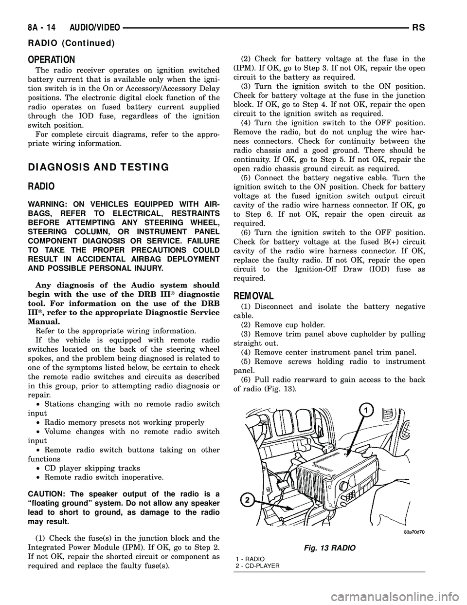
of radio (Fig. 13).
Fig. 13 RADIO
1 - RADIO
2 - CD-PLAYER
8A - 14 AUDIO/VIDEORS
RADIO (Continued)
Page 277 of 2339
SPEAKER
DIAGNOSIS AND TESTING
SPEAKER
WARNING: DISABLE THE AIRBAG SYSTEM
BEFORE ATTEMPTING ANY STEERING WHEEL,
STEERING COLUMN, SEAT BELT TENSIONER, SIDE
AIRBAG, OR INSTRUMENT PANEL COMPONENT
DIAGNOSIS OR SERVICE. DISCONNECT AND ISO-
LATE THE BATTERY NEGATIVE (GROUND) CABLE,
THEN WAIT TWO MINUTES FOR THE AIRBAG SYS-
TEM CAPACITOR TO DISCHARGE BEFORE PER-
FORMING FURTHER DIAGNOSIS OR SERVICE. THIS
IS THE ONLY SURE WAY TO DISABLE THE AIRBAG
SYSTEM. FAILURE TO TAKE THE PROPER PRE-
CAUTIONS COULD RESULT IN ACCIDENTAL AIR-
BAG DEPLOYMENT AND POSSIBLE PERSONAL
INJURY.
Any diagnosis of the Audio system should
begin with the use of the DRB IIItdiagnostic
tool. For information on the use of the DRB
IIIt, refer to the appropriate Diagnostic Service
Manual.
(1) If all speakers are inoperative, check the radio
fuses in the Junction Block (JB). If OK, go to Step 2.
If not OK, repair the shorted circuit or component as
required and replace the faulty fuse.
(2) Check the amplifier fuse (if equipped) in the
junction block. If OK, go to Step 3. If not OK, repair
the shorted circuit or component as required and
replace the faulty fuse.
(3) Turn the ignition switch to the ON position.
Turn the radio receiver ON. Adjust the balance and
fader control controls to check the performance of
each individual speaker. Note the speaker locations
that are not performing correctly. Go to Step 4.
(4) Turn the radio receiver OFF. Turn the ignition
OFF. Disconnect and isolate the battery negative
cable. If vehicle isnotequipped with a amplifier,
remove the radio receiver. If vehicle is equipped with
an amplifier. disconnect wire harness connector at
output side of amplifier. Go to Step 4.
(5) Check both the speaker feed (+) circuit and
return (-) circuit cavities for the inoperative speaker
at the radio receiver wire harness connector for con-
tinuity to ground. There should be no continuity. If
OK, go to Step 5. If not OK, repair the shorted
speaker feed (+) and/or return (-) circuits(s) to the
speaker as required.(6) Disconnect wire harness connector at the inop-
erative speaker. Check for continuity between the
speaker feed (+) circuit cavities of the radio receiver
wire harness connector or if equipped, the amplifier
wire harness connector and the speaker wire harness
connector. Repeat the check between the speaker
return (-) circuit cavities of the radio receiver wire
harness connector and the speaker wire harness con-
nector. In each case, there should be continuity. If
OK, replace the faulty speaker. If not OK, repair the
open speaker feed (+) and/or return (-) circuits(s) as
required.
REMOVAL
D-PILLAR SPEAKER
(1) Disconnect and isolate the battery negative
cable.
(2) Remove rear header trim (right side speaker).
(3) Remove jack cover (left side speaker).
(4) Remove liftgate scuff plate.
(5) Remove upper seat belt bolt. (Refer to 8 -
ELECTRICAL/RESTRAINTS/SEAT BELT OUT-
BOARD FRONT - REMOVAL).
(6) Partially remove quarter trim panel to access
the D-pillar speaker.
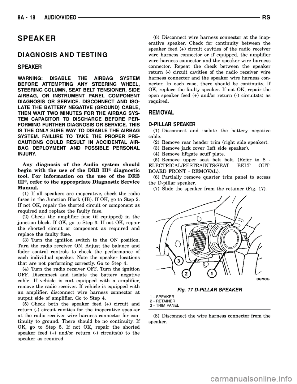
(7) Slide the speaker from the retainer (Fig. 17).
(8) Disconnect the wire harness connector from the
speaker.
Fig. 17 D-PILLAR SPEAKER
1 - SPEAKER
2 - RETAINER
3 - TRIM PANEL
8A - 18 AUDIO/VIDEORS
Page 281 of 2339
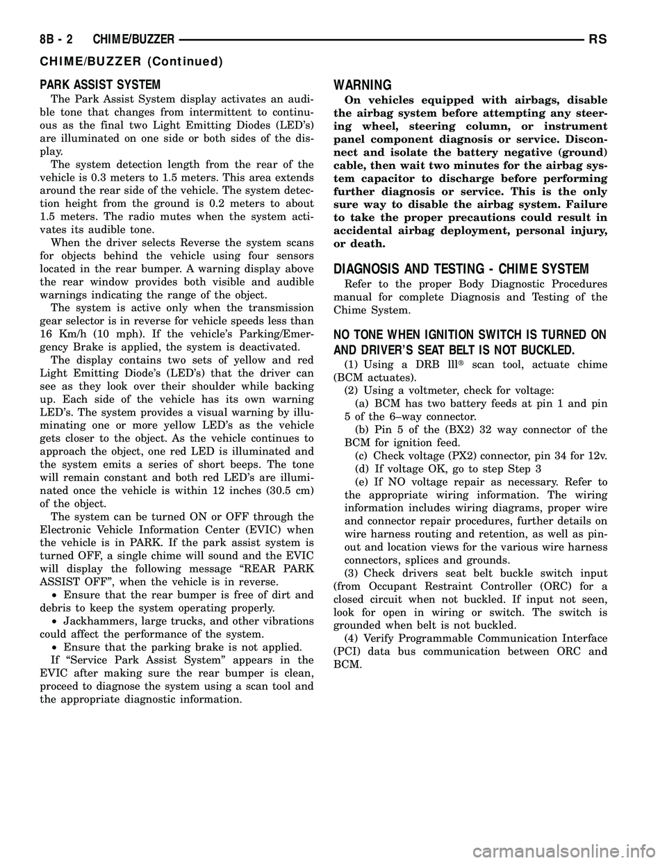
PARK ASSIST SYSTEM
The Park Assist System display activates an audi-
ble tone that changes from intermittent to continu-
ous as the final two Light Emitting Diodes (LED's)
are illuminated on one side or both sides of the dis-
play.
The system detection length from the rear of the
vehicle is 0.3 meters to 1.5 meters. This area extends
around the rear side of the vehicle. The system detec-
tion height from the ground is 0.2 meters to about
1.5 meters. The radio mutes when the system acti-
vates its audible tone.
When the driver selects Reverse the system scans
for objects behind the vehicle using four sensors
located in the rear bumper. A warning display above
the rear window provides both visible and audible
warnings indicating the range of the object.
The system is active only when the transmission
gear selector is in reverse for vehicle speeds less than
16 Km/h (10 mph). If the vehicle's Parking/Emer-
gency Brake is applied, the system is deactivated.
The display contains two sets of yellow and red
Light Emitting Diode's (LED's) that the driver can
see as they look over their shoulder while backing
up. Each side of the vehicle has its own warning
LED's. The system provides a visual warning by illu-
minating one or more yellow LED's as the vehicle
gets closer to the object. As the vehicle continues to
approach the object, one red LED is illuminated and
the system emits a series of short beeps. The tone
will remain constant and both red LED's are illumi-
nated once the vehicle is within 12 inches (30.5 cm)
of the object.
The system can be turned ON or OFF through the
Electronic Vehicle Information Center (EVIC) when
the vehicle is in PARK. If the park assist system is
turned OFF, a single chime will sound and the EVIC
will display the following message ªREAR PARK
ASSIST OFFº, when the vehicle is in reverse.
²Ensure that the rear bumper is free of dirt and
debris to keep the system operating properly.
²Jackhammers, large trucks, and other vibrations
could affect the performance of the system.
²Ensure that the parking brake is not applied.
If ªService Park Assist Systemº appears in the
EVIC after making sure the rear bumper is clean,
proceed to diagnose the system using a scan tool and
the appropriate diagnostic information.
WARNING
On vehicles equipped with airbags, disable
the airbag system before attempting any steer-
ing wheel, steering column, or instrument
panel component diagnosis or service. Discon-
nect and isolate the battery negative (ground)
cable, then wait two minutes for the airbag sys-
tem capacitor to discharge before performing
further diagnosis or service. This is the only
sure way to disable the airbag system. Failure
to take the proper precautions could result in
accidental airbag deployment, personal injury,
or death.
DIAGNOSIS AND TESTING - CHIME SYSTEM
Refer to the proper Body Diagnostic Procedures
manual for complete Diagnosis and Testing of the
Chime System.
NO TONE WHEN IGNITION SWITCH IS TURNED ON
AND DRIVER'S SEAT BELT IS NOT BUCKLED.
(1) Using a DRB llltscan tool, actuate chime
(BCM actuates).
(2) Using a voltmeter, check for voltage:
(a) BCM has two battery feeds at pin 1 and pin
5 of the 6±way connector.
(b) Pin 5 of the (BX2) 32 way connector of the
BCM for ignition feed.
(c) Check voltage (PX2) connector, pin 34 for 12v.
(d) If voltage OK, go to step Step 3
(e) If NO voltage repair as necessary. Refer to
the appropriate wiring information. The wiring
information includes wiring diagrams, proper wire
and connector repair procedures, further details on
wire harness routing and retention, as well as pin-
out and location views for the various wire harness
connectors, splices and grounds.
(3) Check drivers seat belt buckle switch input
(from Occupant Restraint Controller (ORC) for a
closed circuit when not buckled. If input not seen,
look for open in wiring or switch. The switch is
grounded when belt is not buckled.
(4) Verify Programmable Communication Interface
(PCI) data bus communication between ORC and
BCM.
8B - 2 CHIME/BUZZERRS
CHIME/BUZZER (Continued)
Page 288 of 2339
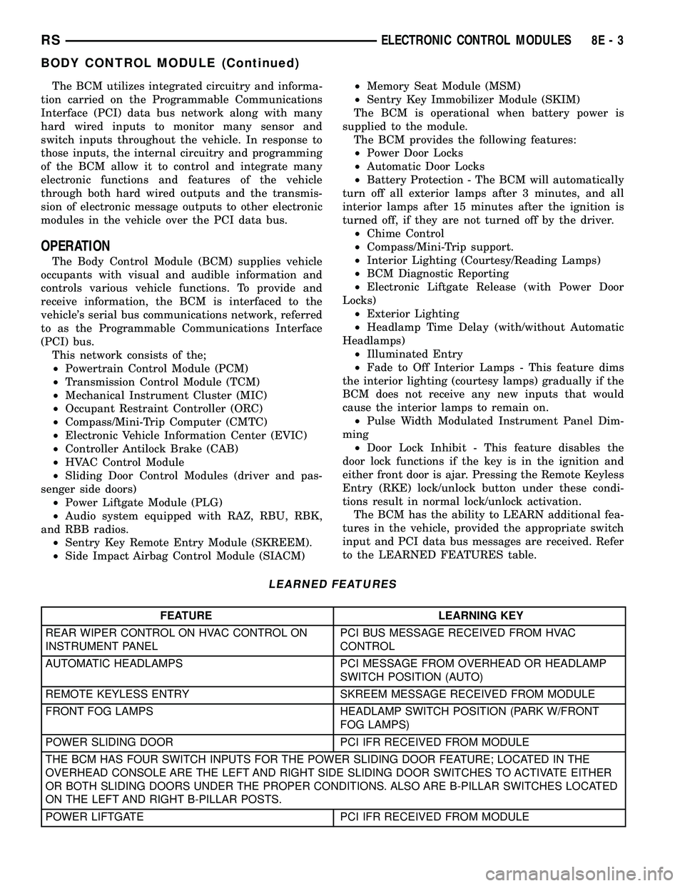
The BCM utilizes integrated circuitry and informa-
tion carried on the Programmable Communications
Interface (PCI) data bus network along with many
hard wired inputs to monitor many sensor and
switch inputs throughout the vehicle. In response to
those inputs, the internal circuitry and programming
of the BCM allow it to control and integrate many
electronic functions and features of the vehicle
through both hard wired outputs and the transmis-
sion of electronic message outputs to other electronic
modules in the vehicle over the PCI data bus.
OPERATION
The Body Control Module (BCM) supplies vehicle
occupants with visual and audible information and
controls various vehicle functions. To provide and
receive information, the BCM is interfaced to the
vehicle's serial bus communications network, referred
to as the Programmable Communications Interface
(PCI) bus.
This network consists of the;
²Powertrain Control Module (PCM)
²Transmission Control Module (TCM)
²Mechanical Instrument Cluster (MIC)
²Occupant Restraint Controller (ORC)
²Compass/Mini-Trip Computer (CMTC)
²Electronic Vehicle Information Center (EVIC)
²Controller Antilock Brake (CAB)
²HVAC Control Module
²Sliding Door Control Modules (driver and pas-
senger side doors)
²Power Liftgate Module (PLG)
²Audio system equipped with RAZ, RBU, RBK,
and RBB radios.
²Sentry Key Remote Entry Module (SKREEM).
²Side Impact Airbag Control Module (SIACM)²Memory Seat Module (MSM)
²Sentry Key Immobilizer Module (SKIM)
The BCM is operational when battery power is
supplied to the module.
The BCM provides the following features:
²Power Door Locks
²Automatic Door Locks
²Battery Protection - The BCM will automatically
turn off all exterior lamps after 3 minutes, and all
interior lamps after 15 minutes after the ignition is
turned off, if they are not turned off by the driver.
²Chime Control
²Compass/Mini-Trip support.
²Interior Lighting (Courtesy/Reading Lamps)
²BCM Diagnostic Reporting
²Electronic Liftgate Release (with Power Door
Locks)
²Exterior Lighting
²Headlamp Time Delay (with/without Automatic
Headlamps)
²Illuminated Entry
²Fade to Off Interior Lamps - This feature dims
the interior lighting (courtesy lamps) gradually if the
BCM does not receive any new inputs that would
cause the interior lamps to remain on.
²Pulse Width Modulated Instrument Panel Dim-
ming
²Door Lock Inhibit - This feature disables the
door lock functions if the key is in the ignition and
either front door is ajar. Pressing the Remote Keyless
Entry (RKE) lock/unlock button under these condi-
tions result in normal lock/unlock activation.
The BCM has the ability to LEARN additional fea-
tures in the vehicle, provided the appropriate switch
input and PCI data bus messages are received. Refer
to the LEARNED FEATURES table.
LEARNED FEATURES
FEATURE LEARNING KEY
REAR WIPER CONTROL ON HVAC CONTROL ON
INSTRUMENT PANELPCI BUS MESSAGE RECEIVED FROM HVAC
CONTROL
AUTOMATIC HEADLAMPS PCI MESSAGE FROM OVERHEAD OR HEADLAMP
SWITCH POSITION (AUTO)
REMOTE KEYLESS ENTRY SKREEM MESSAGE RECEIVED FROM MODULE
FRONT FOG LAMPS HEADLAMP SWITCH POSITION (PARK W/FRONT
FOG LAMPS)
POWER SLIDING DOOR PCI IFR RECEIVED FROM MODULE
THE BCM HAS FOUR SWITCH INPUTS FOR THE POWER SLIDING DOOR FEATURE; LOCATED IN THE
OVERHEAD CONSOLE ARE THE LEFT AND RIGHT SIDE SLIDING DOOR SWITCHES TO ACTIVATE EITHER
OR BOTH SLIDING DOORS UNDER THE PROPER CONDITIONS. ALSO ARE B-PILLAR SWITCHES LOCATED
ON THE LEFT AND RIGHT B-PILLAR POSTS.
POWER LIFTGATE PCI IFR RECEIVED FROM MODULE
RSELECTRONIC CONTROL MODULES8E-3
BODY CONTROL MODULE (Continued)
Page 375 of 2339
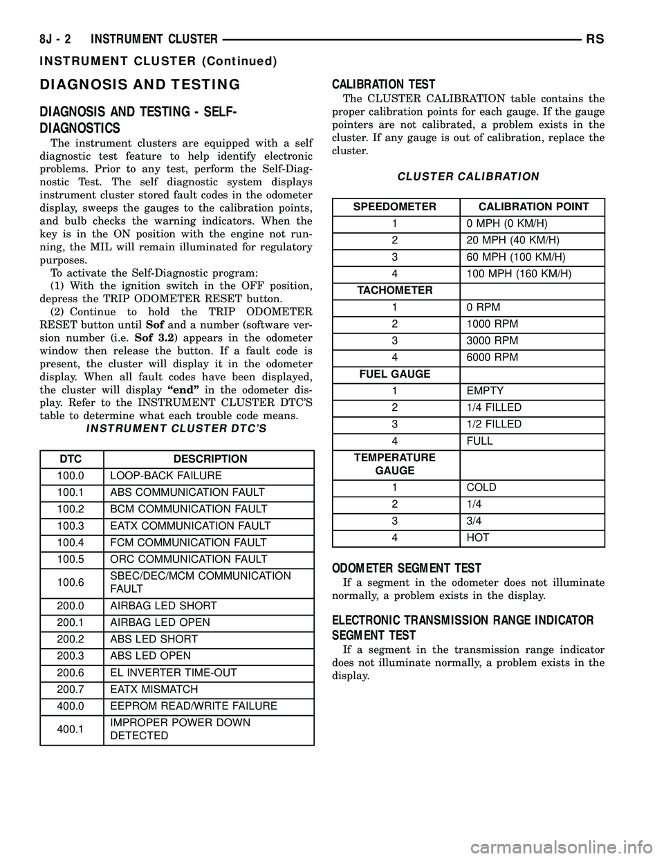
DIAGNOSIS AND TESTING
DIAGNOSIS AND TESTING - SELF-
DIAGNOSTICS
The instrument clusters are equipped with a self
diagnostic test feature to help identify electronic
problems. Prior to any test, perform the Self-Diag-
nostic Test. The self diagnostic system displays
instrument cluster stored fault codes in the odometer
display, sweeps the gauges to the calibration points,
and bulb checks the warning indicators. When the
key is in the ON position with the engine not run-
ning, the MIL will remain illuminated for regulatory
purposes.
To activate the Self-Diagnostic program:
(1) With the ignition switch in the OFF position,
depress the TRIP ODOMETER RESET button.
(2) Continue to hold the TRIP ODOMETER
RESET button untilSofand a number (software ver-
sion number (i.e.Sof 3.2) appears in the odometer
window then release the button. If a fault code is
present, the cluster will display it in the odometer
display. When all fault codes have been displayed,
the cluster will displayªendºin the odometer dis-
play. Refer to the INSTRUMENT CLUSTER DTC'S
table to determine what each trouble code means.
INSTRUMENT CLUSTER DTC'S
DTC DESCRIPTION
100.0 LOOP-BACK FAILURE
100.1 ABS COMMUNICATION FAULT
100.2 BCM COMMUNICATION FAULT
100.3 EATX COMMUNICATION FAULT
100.4 FCM COMMUNICATION FAULT
100.5 ORC COMMUNICATION FAULT
100.6SBEC/DEC/MCM COMMUNICATION
FAULT
200.0 AIRBAG LED SHORT
200.1 AIRBAG LED OPEN
200.2 ABS LED SHORT
200.3 ABS LED OPEN
200.6 EL INVERTER TIME-OUT
200.7 EATX MISMATCH
400.0 EEPROM READ/WRITE FAILURE
400.1IMPROPER POWER DOWN
DETECTED
CALIBRATION TEST
The CLUSTER CALIBRATION table contains the
proper calibration points for each gauge. If the gauge
pointers are not calibrated, a problem exists in the
cluster. If any gauge is out of calibration, replace the
cluster.
CLUSTER CALIBRATION
SPEEDOMETER CALIBRATION POINT
1 0 MPH (0 KM/H)
2 20 MPH (40 KM/H)
3 60 MPH (100 KM/H)
4 100 MPH (160 KM/H)
TACHOMETER
1 0 RPM
2 1000 RPM
3 3000 RPM
4 6000 RPM
FUEL GAUGE
1 EMPTY
2 1/4 FILLED
3 1/2 FILLED
4 FULL
TEMPERATURE
GAUGE
1 COLD
2 1/4
3 3/4
4 HOT
ODOMETER SEGMENT TEST
If a segment in the odometer does not illuminate
normally, a problem exists in the display.
ELECTRONIC TRANSMISSION RANGE INDICATOR
SEGMENT TEST
If a segment in the transmission range indicator
does not illuminate normally, a problem exists in the
display.
8J - 2 INSTRUMENT CLUSTERRS
INSTRUMENT CLUSTER (Continued)
Page 405 of 2339
LAMPS/LIGHTING - INTERIOR
TABLE OF CONTENTS
page page
LAMPS/LIGHTING - INTERIOR
SPECIFICATIONS
INTERIOR LAMPS.....................20
CENTER CONSOLE LAMP
REMOVAL.............................21
INSTALLATION.........................21
CENTER CONSOLE LAMP SWITCH
REMOVAL.............................21
INSTALLATION.........................21
CLUSTER ILLUMINATION LAMPS
REMOVAL.............................21
INSTALLATION.........................21
COURTESY LAMP
REMOVAL.............................21
INSTALLATION.........................21DOME/CARGO LAMP
REMOVAL.............................22
INSTALLATION.........................22
GLOVE BOX LAMP SWITCH
REMOVAL.............................22
INSTALLATION.........................22
LIFTGATE LAMP
REMOVAL.............................22
INSTALLATION.........................22
READING LAMP
REMOVAL.............................22
INSTALLATION.........................23
VANITY LAMP
REMOVAL.............................24
INSTALLATION.........................24
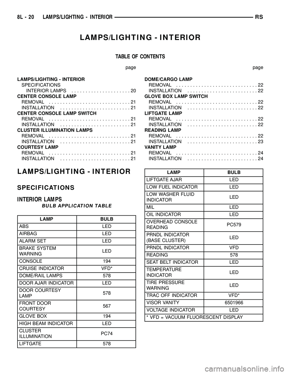
LAMPS/LIGHTING - INTERIOR
SPECIFICATIONS
INTERIOR LAMPS
BULB APPLICATION TABLE
LAMP BULB
ABS LED
AIRBAG LED
ALARM SET LED
BRAKE SYSTEM
WARNINGLED
CONSOLE 194
CRUISE INDICATOR VFD*
DOME/RAIL LAMPS 578
DOOR AJAR INDICATOR LED
DOOR COURTESY
LAMP578
FRONT DOOR
COURTESY567
GLOVE BOX 194
HIGH BEAM INDICATOR LED
CLUSTER
ILLUMINATIONPC74
LIFTGATE 578
LAMP BULB
LIFTGATE AJAR LED
LOW FUEL INDICATOR LED
LOW WASHER FLUID
INDICATORLED
MIL LED
OIL INDICATOR LED
OVERHEAD CONSOLE
READINGPC579
PRNDL INDICATOR
(BASE CLUSTER)LED
PRNDL INDICATOR VFD
READING 578
SEAT BELT INDICATOR LED
TEMPERATURE
INDICATORLED
TIRE PRESSURE
WARNINGLED
TRAC OFF INDICATOR VFD*
VISOR VANITY 6501966
VOLTAGE INDICATOR LED
* VFD = VACUUM FLUORESCENT DISPLAY
8L - 20 LAMPS/LIGHTING - INTERIORRS
Page 456 of 2339
self-resetting circuit breaker to protect them from
overload. However, consecutive or frequent resetting
of the circuit breaker must not be allowed to con-
tinue, or the motor may be damaged.
MEMORY SYSTEM
The Memory Seat Mirror Module (MSMM) receives
battery current through fuse #22 in the Integrated
Power Module (IPM) and the power seat system cir-
cuit breaker, located under the driver side front seat
near the rear edge of the seat cushion pan. The mem-
ory system does not operate with the Ignition-Off
Draw (IOD) fuse removed. The MSMM will drive a
maximum of 2 motors at a time in a given direction.
If conflicting directions are requested, the priority for
response will be approximately as follows:
²Seat Track Rearward or Forward
²Seat Front Down or Up
²Seat Rear Down or Up
²Recliner Rearward or Forward
The inputs from these switches to the MSMM is a
current limited battery source fed by the MSMM.
This protects the MSMM printed circuit board traces
from acting as fuses. All of these switch contact
inputs to the MSMM are normally closed to ground,
except when actuated.
For diagnosis of the MSMM, the Programmable
Communication Interface (PCI) data bus, or the other
electronic modules on the PCI data bus that provide
inputs and outputs for the memory system, the use of
a DRBIIItor equivalent scan tool and the proper
Diagnostic Procedures information is recommended.
ELECTRONIC VEHICLE INFORMATION CENTER
The Electronic Vehicle Information Center (EVIC)
serves as the user interface for the memory system.
It displays memory system status messages and pro-
vides the user with the means for enabling and dis-
abling the many customer programmable features
available on the vehicle, including those for the mem-
ory system.
(Refer to 8 - ELECTRICAL/OVERHEAD CON-
SOLE/ELECTRONIC VEHICLE INFO CENTER -
DESCRIPTION) for additional information on the
EVIC.
DIAGNOSIS AND TESTING
POWER SEAT SYSTEM
Following are tests that will help to diagnose the
hard wired components and circuits of the power seat
system. However, if the vehicle is also equipped with
the optional memory system, these tests may not
prove conclusive in the diagnosis of the driver side
power seat. In order to obtain conclusive testing ofthe driver side power seat with the memory system
option, the Programmable Communications Interface
(PCI) data bus network and all of the electronic mod-
ules that provide inputs to, or receive outputs from
the memory system components must be checked,
(Refer to 8 - ELECTRICAL/POWER SEATS - DIAG-
NOSIS AND TESTING).
WARNING: SOME VEHICLES ARE EQUIPPED WITH
SEATBACK MOUNTED AIRBAGS. BEFORE
ATTEMPTING TO DIAGNOSE OR SERVICE ANY
SEAT OR POWER SEAT SYSTEM COMPONENT
YOU MUST FIRST DISCONNECT AND ISOLATE THE
BATTERY NEGATIVE CABLE. THEN WAIT TWO MIN-
UTES FOR THE SYSTEM CAPACITOR TO DIS-
CHARGE BEFORE FURTHER SYSTEM SERVICE.
THIS IS THE ONLY SURE WAY TO DISABLE THE
AIRBAG SYSTEM. FAILURE TO DO SO COULD
RESULT IN ACCIDENTAL AIRBAG DEPLOYMENT
AND POSSIBLE PERSONAL INJURY.
(1) If either power seat is completely inoperable,
check the power seat circuit breaker, located under
the trailing edge of the driver side power seat. If the
power seat circuit breaker is OK, continue to the
next step.
(2) Check for proper battery and ground connec-
tions at the power seat switch and/or memory seat
module. Repair any wiring as necessary.
(3) Check the power seat system wire harness con-
nections and pins to ensure proper circuit continuity
and ground paths.
MEMORY SYSTEM
In order to obtain conclusive testing of the memory
system, the Programmable Communications Interface
(PCI) data bus network and all of the electronic mod-
ules that provide inputs to, or receive outputs from
the memory system components must be checked.
The most reliable, efficient, and accurate means to
diagnose the driver side power seat with the memory
system option requires the use of a DRBIIItor
equivalent scan tool and the proper Diagnostic Proce-
dures information. The DRBIIItscan tool can pro-
vide confirmation that the PCI data bus is functional,
that all of the electronic modules are sending and
receiving the proper messages on the PCI data bus,
and that the memory system is receiving the proper
hard wired inputs and relaying the proper hard
wired outputs to perform its driver side power seat
functions.
(1) If the driver power seat exhibits an interrupted
or jerky motion, ensure the wire harness is connected
correctly. To verify the concern, obtain a DRB IIItor
equivalent scan tool and energize each axis one at a
time. If any axis stops in approximately 2 seconds
(without hitting the end of travel), the feedback for
RSPOWER SEAT SYSTEM8N-33
POWER SEAT SYSTEM (Continued)
Page 491 of 2339
²Occupant Classification Module- Vehicles
equipped with the Occupant Classification System
(OCS) include an Occupant Classification Module
(OCM) which is secured to a stamped steel mounting
bracket on the underside of the passenger side front
seat cushion frame.
²Occupant Restraint Controller- The Occu-
pant Restraint Controller (ORC) is also sometimes
referred to as the Airbag Control Module (ACM). The
ORC is located on a mount on the floor transmission
tunnel just underneath the instrument panel center
stack (Fig. 3).
²Passenger Airbag- The passenger airbag is
located on the instrument panel, beneath the instru-
ment panel top pad and above the glove box on the
passenger side of the vehicle (Fig. 3).
²Passenger Airbag Disabled (PAD) Indicator
- Vehicles equipped with the Occupant Classification
System (OCS) include a passenger airbag disabled
(PAD) indicator which is located in the instrument
panel center stack (Fig. 3).
²Passenger Knee Blocker- The passenger knee
blocker is a structural reinforcement that is integral
to and concealed within the glove box door (Fig. 3).
²Seat Belt Tensioner- A seat belt tensioner is
integral to both front seat belt buckles. The seat belt
buckles are secured to the inner seat frame sides,
beneath a cushion trim panel.
²Seat Weight Bladder and Pressure Sensor
Assembly- Vehicles equipped with the Occupant
Classification System (OCS) include a seat weight
bladder that is sandwiched between an insulator pad
on the top of the passenger side front seat pan and
the seat cushion foam padding. A short hose connects
the bladder to a pressure sensor which is secured to
the Occupant Classification Module (OCM) mounting
bracket on the underside of the passenger side front
seat cushion frame.
²Side Impact Sensors- Six side impact sensors
are used on vehicles equipped with the curtain air-
bags, three left side and three right side. The first
row side impact sensor is located in the B-pillar, just
above the front seat belt retractor. The second row
side impact sensor is located in the sliding side door
track opening, just in front of the C-pillar. The third
row side impact sensor is located behind the quarter
trim panel, above the rear tire wheel well, between
the C and D-pillars.
The ORC, the OCM, and the cluster each contain a
microprocessor and programming that allow them to
communicate with each other using the Programma-
ble Communications Interface (PCI) data bus net-
work. This method of communication is used by the
ORC for control of the airbag indicators.OPERATION
ACTIVE RESTRAINTS
The primary passenger restraints in this or any
other vehicle are the seat belts and child restraint
anchors. Seat belts and child restraint anchors are
referred to as an active restraint because the vehicle
occupants are required to physically fasten and prop-
erly adjust these restraints in order to benefit from
them. See the owner's manual in the vehicle glove
box for more information on the features, use and
operation of all of the active restraints.
PASSIVE RESTRAINTS
The passive restraints are referred to as a supple-
mental restraint system because they were designed
and are intended to enhance the protection for the
occupants of the vehicleONLYwhen used in con-
junction with the seat belts. They are referred to as
passive restraints because the vehicle occupants are
not required to do anything to make them operate;
however, the vehicle occupants must be wearing their
seat belts in order to obtain the maximum safety
benefit from the supplemental restraint system.
The supplemental restraint system electrical cir-
cuits are continuously monitored and controlled by a
microprocessor and software contained within the
Occupant Restraint Controller (ORC). An airbag indi-
cator in the ElectroMechanical Instrument Cluster
(EMIC) illuminates for about seven seconds as a bulb
test each time the ignition switch is turned to the
ON or START positions. Following the bulb test, the
airbag indicator is turned ON or OFF by the ORC to
indicate the status of the supplemental restraint sys-
tem. If the airbag indicator comes ON at any time
other than during the bulb test, it indicates that
there is a problem in the supplemental restraint sys-
tem electrical circuits. Such a problem may cause air-
bags not to deploy when required, or to deploy when
not required.
Deployment of the supplemental restraints
depends upon the angle and severity of an impact.
Deployment is not based upon vehicle speed; rather,
deployment is based upon the rate of deceleration as
measured by the forces of gravity (G force) upon the
impact sensors. When an impact is severe enough,
the microprocessor in the ORC signals the inflator of
the appropriate airbag units to deploy their airbag
cushions. The front seat belt tensioners are provided
with a deployment signal by the ORC in conjunction
with the front airbags. During a frontal vehicle
impact, the knee blockers work in concert with prop-
erly fastened and adjusted seat belts to restrain both
the driver and the front seat passenger in the proper
position for an airbag deployment. The knee blockers
also absorb and distribute the crash energy from the
8O - 4 RESTRAINTSRS
RESTRAINTS (Continued)
Page 492 of 2339
driver and the front seat passenger to the structure
of the instrument panel (Refer to 8 - ELECTRICAL/
RESTRAINTS/KNEE BLOCKER AIRBAG -
DESCRIPTION). The seat belt tensioners remove the
slack from the front seat belts to provide further
assurance that the driver and front seat passenger
are properly positioned and restrained for an airbag
deployment.
When the ORC monitors a problem in any of the
dual front airbag system circuits or components,
including the seat belt tensioners, it stores a Diag-
nostic Trouble Code (DTC) in its memory and sends
an electronic message to the EMIC to turn on the
airbag indicator. Proper testing of the supplemental
restraint system components, the Programmable
Communications Interface (PCI) data bus, the elec-
tronic message inputs to and outputs from the EMIC
or the ORC, as well as the retrieval or erasure of a
DTC from the ORC or the EMIC requires the use of
a scan tool. Refer to the appropriate diagnostic infor-
mation.
OCCUPANT CLASSIFICATION SYSTEM
The Occupant Classification System (OCS) auto-
matically suppresses or enables passenger airbag and
seat belt tensioner operation based upon whether or
not the passenger side front seat is occupied and, if
the seat is occupied, classifies the size of the occu-
pant and whether the seat is occupied by a child
seat.
The OCS has an Occupant Classification Module
(OCM) that monitors inputs from the seat weight
bladder pressure sensor under the passenger side
front seat cushion and from the belt tension sensor
on the passenger side front seat belt lower anchor.
Based upon those inputs the microprocessor within
the OCM classifies the occupant of the passenger
side front seat. The OCM then sends electronic occu-
pant classification messages to the ORC. The micro-
processor and programming of the ORC uses these
occupant classification messages to determine
whether to enable or disable the deployment circuits
for the passenger airbag and seat belt tensioner.
The OCS electrical circuits and components are
continuously monitored by the OCM, and the OCM is
continuously monitored by the ORC. A passenger air-
bag ON/OFF indicator is located in the instrument
panel center stack area. This indicator receives bat-
tery current whenever the ignition switch is in the
ON or START positions, and illuminates only when
the ORC pulls the indicator control circuit to ground.
The indicator illuminates for about seven seconds as
a bulb test each time the ignition switch is turned to
the ON or START positions. Following the bulb test,
the indicator is turned ON or OFF by the ORC based
upon the electronic occupant classification messagesreceived from the OCM. This indicator is illuminated
whenever the passenger airbag and seat belt ten-
sioner operation has been suppressed, and is turned
OFF whenever they are enabled or when the passen-
ger seat is classified as empty.
When the OCM monitors a problem in any of the
OCS circuits or components, it stores a fault code or
DTC in its memory circuit and sends an electronic
message to the ORC. The ORC then sends an elec-
tronic message to the EMIC to turn ON the airbag
indicator. If for any reason the OCM is unable to
classify the occupant it sends an electronic message
to the ORC, and the ORC suppresses passenger air-
bag and seat belt tensioner operation. Proper testing
of the OCS components, the Programmable Commu-
nications Interface (PCI) data bus, the electronic
message inputs to and outputs from the OCM, the
EMIC or the ORC, as well as the retrieval or erasure
of a DTC's, requires the use of a scan tool. Refer to
the appropriate diagnostic information.
WARNING
WARNINGS
Disconnect and isolate the battery negative
cable before beginning any airbag system com-
ponent diagnosis, testing, removal, or installa-
tion procedures. Allow system capacitor to
discharge for two minutes before beginning any
component testing or service. This will disable
the airbag system. Failure to disconnect the
battery negative cable may result in accidental
airbag deployment, personal injury, or death.
Do not place an intact undeployed airbag
face down on a solid surface. The airbag will
propel into the air if accidentally deployed and
may result in personal injury or death.
When carrying or handling an undeployed
airbag, the trim side (face) of the airbag should
be pointing towards the body to minimize pos-
sibility of injury if accidental deployment
occurs. Failure to do this may result in per-
sonal injury or death.
Replace airbag system components with
Mopartreplacement parts. Substitute parts
may appear interchangeable, but internal dif-
ferences may result in inferior occupant protec-
tion. Failure to do so may result in occupant
personal injury or death.
Wear safety glasses, rubber gloves, and long
sleeved clothing when cleaning powder residue
from vehicle after airbag deployment. Sodium
hydroxide powder residue emitted from a
deployed airbag can cause skin irritation.
Flush affected area with cool water if irritation
is experienced. If nasal or throat irritation is
RSRESTRAINTS8O-5
RESTRAINTS (Continued)