odometer CHRYSLER CARAVAN 2005 Service Manual
[x] Cancel search | Manufacturer: CHRYSLER, Model Year: 2005, Model line: CARAVAN, Model: CHRYSLER CARAVAN 2005Pages: 2339, PDF Size: 59.69 MB
Page 287 of 2339
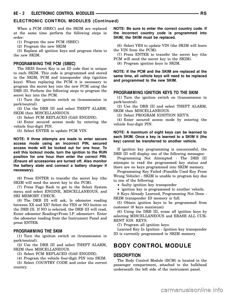
When a PCM (SBEC) and the SKIM are replaced
at the same time perform the following steps in
order:
(1) Program the new PCM (SBEC)
(2) Program the new SKIM
(3) Replace all ignition keys and program them to
the new SKIM.
PROGRAMMING THE PCM (SBEC)
The SKIS Secret Key is an ID code that is unique
to each SKIM. This code is programmed and stored
in the SKIM, PCM and transponder chip (ignition
keys). When replacing the PCM it is necessary to
program the secret key into the new PCM using the
DRB III. Perform the following steps to program the
secret key into the PCM.
(1) Turn the ignition switch on (transmission in
park/neutral).
(2) Use the DRB III and select THEFT ALARM,
SKIM then MISCELLANEOUS.
(3) Select PCM REPLACED (GAS ENGINE).
(4) Enter secured access mode by entering the
vehicle four-digit PIN.
(5) Select ENTER to update PCM VIN.
NOTE: If three attempts are made to enter secure
access mode using an incorrect PIN, secured
access mode will be locked out for one hour. To
exit this lockout mode, turn the ignition to the RUN
position for one hour then enter the correct PIN.
(Ensure all accessories are turned off. Also monitor
the battery state and connect a battery charger if
necessary).
(6) Press ENTER to transfer the secret key (the
SKIM will send the secret key to the PCM).
(7) Press Page Back to get to the Select System
menu and select ENGINE, MISCELLANEOUS, and
SRI MEMORY CHECK.
(8) The DRB III will ask, Is odometer reading
between XX and XX? Select the YES or NO button on
the DRB III. If NO is selected, the DRB III will read,
Enter odometer Reading
the odometer reading from the Instrument Panel and
press ENTER.
PROGRAMMING THE SKIM
(1) Turn the ignition switch on (transmission in
park/neutral).
(2) Use the DRB III and select THEFT ALARM,
SKIM then MISCELLANEOUS.
(3) Select PCM REPLACED (GAS ENGINE).
(4) Program the vehicle four-digit PIN into SKIM.
(5) Select COUNTRY CODE and enter the correct
country.NOTE: Be sure to enter the correct country code. If
the incorrect country code is programmed into
SKIM, the SKIM must be replaced.
(6) Select YES to update VIN (the SKIM will learn
the VIN from the PCM).
(7) Press ENTER to transfer the secret key (the
PCM will send the secret key to the SKIM).
(8) Program ignition keys to SKIM.
NOTE: If the PCM and the SKIM are replaced at the
same time, all vehicle keys will need to be replaced
and programmed to the new SKIM.
PROGRAMMING IGNITION KEYS TO THE SKIM
(1) Turn the ignition switch on (transmission in
park/neutral).
(2) Use the DRB III and select THEFT ALARM,
SKIM then MISCELLANEOUS.
(3) Select PROGRAM IGNITION KEY'S.
(4) Enter secured access mode by entering the
vehicle four-digit PIN.
NOTE: A maximum of eight keys can be learned to
each SKIM. Once a key is learned to a SKIM it (the
key) cannot be transferred to another vehicle.
If ignition key programming is unsuccessful, the
DRB III will display one of the following messages:
Programming Not Attempted - The DRB III
attempts to read the programmed key status and
there are no keys programmed into SKIM memory.
Programming Key Failed (Possible Used Key From
Wrong Vehicle) - SKIM is unable to program key due
to one of the following:
²faulty ignition key transponder
²ignition key is programmed to another vehicle.
8 Keys Already Learned, Programming Not Done -
SKIM transponder ID memory is full.
(5) Obtain ignition keys to be programmed from
customer (8 keys maximum).
(6) Using the DRB III, erase all ignition keys by
selecting MISCELLANEOUS and ERASE ALL CUR-
RENT IGN. KEYS.
(7) Program all ignition keys.
Learned Key In Ignition - Ignition key transponder
ID is currently programmed in SKIM memory.
BODY CONTROL MODULE
DESCRIPTION
The Body Control Module (BCM) is located in the
passenger compartment, attached to the bulkhead
underneath the left side of the instrument panel.
8E - 2 ELECTRONIC CONTROL MODULESRS
ELECTRONIC CONTROL MODULES (Continued)
Page 374 of 2339
INSTRUMENT CLUSTER
TABLE OF CONTENTS
page page
INSTRUMENT CLUSTER
DESCRIPTION..........................1
OPERATION............................1
DIAGNOSIS AND TESTING
DIAGNOSIS AND TESTING - SELF-
DIAGNOSTICS.........................2
DIAGNOSIS AND TESTING - CLUSTER
DIAGNOSIS...........................3REMOVAL.............................11
INSTALLATION.........................11
CLUSTER LENS
REMOVAL.............................11
INSTALLATION.........................11
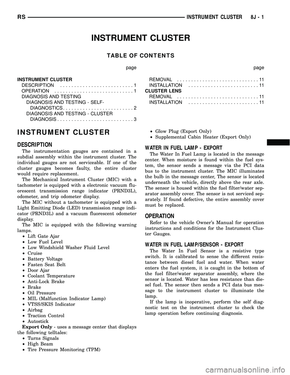
INSTRUMENT CLUSTER
DESCRIPTION
The instrumentation gauges are contained in a
subdial assembly within the instrument cluster. The
individual gauges are not serviceable. If one of the
cluster gauges becomes faulty, the entire cluster
would require replacement.
The Mechanical Instrument Cluster (MIC) with a
tachometer is equipped with a electronic vacuum flu-
orescent transmission range indicator (PRND3L),
odometer, and trip odometer display.
The MIC without a tachometer is equipped with a
Light Emitting Diode (LED) transmission range indi-
cator (PRND3L) and a vacuum fluorescent odometer
display.
The MIC is equipped with the following warning
lamps.
²Lift Gate Ajar
²Low Fuel Level
²Low Windshield Washer Fluid Level
²Cruise
²Battery Voltage
²Fasten Seat Belt
²Door Ajar
²Coolant Temperature
²Anti-Lock Brake
²Brake
²Oil Pressure
²MIL (Malfunction Indicator Lamp)
²VTSS/SKIS Indicator
²Airbag
²Traction Control
²Autostick
Export Only- uses a message center that displays
the following telltales:
²Turns Signals
²High Beam
²Tire Pressure Monitoring (TPM)²Glow Plug (Export Only)
²Supplemental Cabin Heater (Export Only)WATER IN FUEL LAMP - EXPORT
The Water In Fuel Lamp is located in the message
center. When moisture is found within the fuel sys-
tem, the sensor sends a message via the PCI data
bus to the instrument cluster. The MIC illuminates
the bulb in the message center, The sensor is located
underneath the vehicle, directly above the rear axle.
The sensor is housed within the fuel filter/water sep-
arator assembly cover. The sensor is not serviced sep-
arately. If found defective, the entire assembly cover
must be replaced.
OPERATION
Refer to the vehicle Owner's Manual for operation
instructions and conditions for the Instrument Clus-
ter Gauges.
WATER IN FUEL LAMP/SENSOR - EXPORT
The Water In Fuel Sensor is a resistive type
switch. It is calibrated to sense the different resis-
tance between diesel fuel and water. When water
enters the fuel system, it is caught in the bottom of
the fuel filter/water separator assembly, where the
sensor is located. Water has less resistance than die-
sel fuel. The sensor then sends a PCI data bus mes-
sage to the instrument cluster to illuminate the
lamp.
If the lamp is inoperative, perform the self diag-
nostic test on the instrument cluster to check the
lamp operation before continuing diagnosis.
RSINSTRUMENT CLUSTER8J-1
Page 375 of 2339
DIAGNOSIS AND TESTING
DIAGNOSIS AND TESTING - SELF-
DIAGNOSTICS
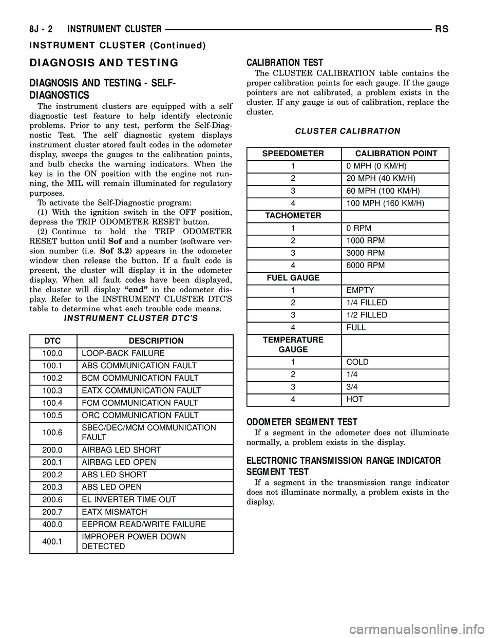
The instrument clusters are equipped with a self
diagnostic test feature to help identify electronic
problems. Prior to any test, perform the Self-Diag-
nostic Test. The self diagnostic system displays
instrument cluster stored fault codes in the odometer
display, sweeps the gauges to the calibration points,
and bulb checks the warning indicators. When the
key is in the ON position with the engine not run-
ning, the MIL will remain illuminated for regulatory
purposes.
To activate the Self-Diagnostic program:
(1) With the ignition switch in the OFF position,
depress the TRIP ODOMETER RESET button.
(2) Continue to hold the TRIP ODOMETER
RESET button untilSofand a number (software ver-
sion number (i.e.Sof 3.2) appears in the odometer
window then release the button. If a fault code is
present, the cluster will display it in the odometer
display. When all fault codes have been displayed,
the cluster will displayªendºin the odometer dis-
play. Refer to the INSTRUMENT CLUSTER DTC'S
table to determine what each trouble code means.
INSTRUMENT CLUSTER DTC'S
DTC DESCRIPTION
100.0 LOOP-BACK FAILURE
100.1 ABS COMMUNICATION FAULT
100.2 BCM COMMUNICATION FAULT
100.3 EATX COMMUNICATION FAULT
100.4 FCM COMMUNICATION FAULT
100.5 ORC COMMUNICATION FAULT
100.6SBEC/DEC/MCM COMMUNICATION
FAULT
200.0 AIRBAG LED SHORT
200.1 AIRBAG LED OPEN
200.2 ABS LED SHORT
200.3 ABS LED OPEN
200.6 EL INVERTER TIME-OUT
200.7 EATX MISMATCH
400.0 EEPROM READ/WRITE FAILURE
400.1IMPROPER POWER DOWN
DETECTED
CALIBRATION TEST
The CLUSTER CALIBRATION table contains the
proper calibration points for each gauge. If the gauge
pointers are not calibrated, a problem exists in the
cluster. If any gauge is out of calibration, replace the
cluster.
CLUSTER CALIBRATION
SPEEDOMETER CALIBRATION POINT
1 0 MPH (0 KM/H)
2 20 MPH (40 KM/H)
3 60 MPH (100 KM/H)
4 100 MPH (160 KM/H)
TACHOMETER
1 0 RPM
2 1000 RPM
3 3000 RPM
4 6000 RPM
FUEL GAUGE
1 EMPTY
2 1/4 FILLED
3 1/2 FILLED
4 FULL
TEMPERATURE
GAUGE
1 COLD
2 1/4
3 3/4
4 HOT
ODOMETER SEGMENT TEST
If a segment in the odometer does not illuminate
normally, a problem exists in the display.
ELECTRONIC TRANSMISSION RANGE INDICATOR
SEGMENT TEST
If a segment in the transmission range indicator
does not illuminate normally, a problem exists in the
display.
8J - 2 INSTRUMENT CLUSTERRS
INSTRUMENT CLUSTER (Continued)
Page 376 of 2339
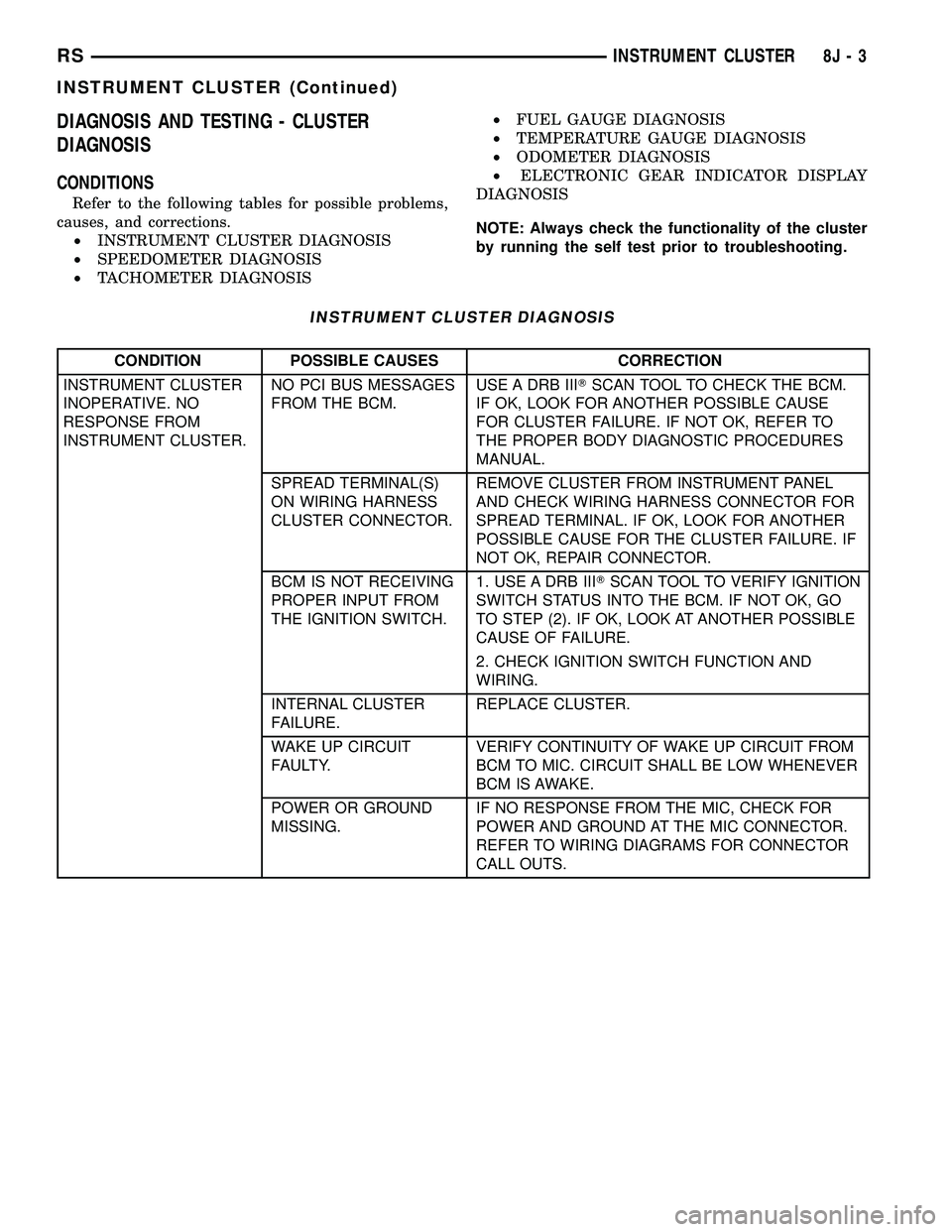
DIAGNOSIS AND TESTING - CLUSTER
DIAGNOSIS
CONDITIONS
Refer to the following tables for possible problems,
causes, and corrections.
²INSTRUMENT CLUSTER DIAGNOSIS
²SPEEDOMETER DIAGNOSIS
²TACHOMETER DIAGNOSIS²FUEL GAUGE DIAGNOSIS
²TEMPERATURE GAUGE DIAGNOSIS
²ODOMETER DIAGNOSIS
²ELECTRONIC GEAR INDICATOR DISPLAY
DIAGNOSIS
NOTE: Always check the functionality of the cluster
by running the self test prior to troubleshooting.
INSTRUMENT CLUSTER DIAGNOSIS
CONDITION POSSIBLE CAUSES CORRECTION
INSTRUMENT CLUSTER
INOPERATIVE. NO
RESPONSE FROM
INSTRUMENT CLUSTER.NO PCI BUS MESSAGES
FROM THE BCM.USE A DRB IIITSCAN TOOL TO CHECK THE BCM.
IF OK, LOOK FOR ANOTHER POSSIBLE CAUSE
FOR CLUSTER FAILURE. IF NOT OK, REFER TO
THE PROPER BODY DIAGNOSTIC PROCEDURES
MANUAL.
SPREAD TERMINAL(S)
ON WIRING HARNESS
CLUSTER CONNECTOR.REMOVE CLUSTER FROM INSTRUMENT PANEL
AND CHECK WIRING HARNESS CONNECTOR FOR
SPREAD TERMINAL. IF OK, LOOK FOR ANOTHER
POSSIBLE CAUSE FOR THE CLUSTER FAILURE. IF
NOT OK, REPAIR CONNECTOR.
BCM IS NOT RECEIVING
PROPER INPUT FROM
THE IGNITION SWITCH.1. USE A DRB IIITSCAN TOOL TO VERIFY IGNITION
SWITCH STATUS INTO THE BCM. IF NOT OK, GO
TO STEP (2). IF OK, LOOK AT ANOTHER POSSIBLE
CAUSE OF FAILURE.
2. CHECK IGNITION SWITCH FUNCTION AND
WIRING.
INTERNAL CLUSTER
FAILURE.REPLACE CLUSTER.
WAKE UP CIRCUIT
FAULTY.VERIFY CONTINUITY OF WAKE UP CIRCUIT FROM
BCM TO MIC. CIRCUIT SHALL BE LOW WHENEVER
BCM IS AWAKE.
POWER OR GROUND
MISSING.IF NO RESPONSE FROM THE MIC, CHECK FOR
POWER AND GROUND AT THE MIC CONNECTOR.
REFER TO WIRING DIAGRAMS FOR CONNECTOR
CALL OUTS.
RSINSTRUMENT CLUSTER8J-3
INSTRUMENT CLUSTER (Continued)
Page 382 of 2339

CONDITION POSSIBLE CAUSES CORRECTION
ERRATIC POINTER
MOVEMENT.1. BAD PCI BUS
MESSAGE FROM THE
POWERTRAIN CONTROL
MODULE.1.A. CHECK PCM FAULT CODES USING A DRB IIIT
SCAN TOOL. IF THERE ARE NO FAULTS, GO TO
STEP 1.B. IF THERE ARE FAULTS, REFER TO THE
PROPER POWERTRAIN DIAGNOSTIC
PROCEDURES MANUAL TO PROPERLY DIAGNOSE
AND REPAIR.
1.B. REFER TO FUEL, COOLANT TEMPERATURE
SENSOR, DIAGNOSIS AND TESTING. REPAIR
SENSOR AS NEEDED.
2. INTERNAL CLUSTER
FAILURE.2. PERFORM CLUSTER SELF-DIAGNOSTIC TEST
AND CHECK FOR FAULT CODES.
²IF THE POINTER MOVES DURING TEST BUT
STILL APPEARS ERRATIC, REPLACE CLUSTER
ASSEMBLY.
TEMPERATURE GAUGE
INACCURATE.1. TEMPERATURE
GAUGE OUT OF
CALIBRATION.1. PERFORM CLUSTER SELF-DIAGNOSTIC TEST.
²IF POINTER IS ACCURATE TO THE CALIBRATION
POINTS LOOK FOR ANOTHER POSSIBLE CAUSE
OF FAILURE.
²IF POINTER IS INACCURATE TO THE
CALIBRATION POINTS, REPLACE CLUSTER
ASSEMBLY.
2. COOLANT SENSOR
OUT OF CALIBRATION.2. REFER TO FUEL, COOLANT TEMPERATURE
SENSOR FOR TEST AND REPAIR PROCEDURE.
ODOMETER DIAGNOSIS
CONDITION POSSIBLE CAUSES CORRECTION
NO DISPLAY. 1. NO PCI BUS
ODOMETER MESSAGE
FROM BCM.1. USE A DRB IIITSCAN TOOL TO CHECK THE BCM.
REFER TO THE PROPER BODY DIAGNOSTIC
PROCEDURES MANUAL TO PROPERLY DIAGNOSE
AND REPAIR.
2. INTERNAL CLUSTER
FAILURE.2. PERFORM CLUSTER SELF-DIAGNOSTIC TEST
AND CHECK FOR FAULT CODES.
²IF ODOMETER PASSES THE SEGMENT CHECK,
LOOK FOR ANOTHER POSSIBLE CAUSE OF
FAILURE. IF IT FAILS VERIFY POWER AND
GROUND ARE BEING PROVIDED TO THE
CLUSTER. IF YES, REPLACE CLUSTER. IF NO,
DETERMINE CAUSE OF NO POWER OR GROUND.
RSINSTRUMENT CLUSTER8J-9
INSTRUMENT CLUSTER (Continued)
Page 383 of 2339

CONDITION POSSIBLE CAUSES CORRECTION
ERRATIC DISPLAY 1. INTERNAL CLUSTER
FAILURE.1. PERFORM CLUSTER SELF-DIAGNOSTIC TEST
AND CHECK FOR FAULT CODES.
²IF ODOMETER PASSES THE SEGMENT TEST,
FAILURE MAY NOT BE IN THE CLUSTER. LOOK
FOR ANOTHER POSSIBLE CAUSE OF FAILURE.
2. VERIFY GOOD POWER AND GROUND
CONNECTIONS. IF CONNECTIONS ARE GOOD AND
NO OTHER PROBLEMS ARE FOUND, REPLACE
CLUSTER ASSEMBLY.
2. BAD PCI BUS
MESSAGE FROM THE
BCM.2. USE A DRB IIITSCAN TOOL TO CHECK THE BCM.
REFER TO THE PROPER BODY DIAGNOSTIC
PROCEDURES MANUAL TO PROPERLY DIAGNOSE
AND REPAIR.
ODOMETER WON'T GO
INTO TRIP MODE.TRIP SWITCH DOESN'T
WORK.IF CLUSTER WILL NOT GO INTO SELF DIAGNOSTIC
MODE AND CANNOT TOGGLE BETWEEN
ODOMETER AND TRIP ODOMETER, REPLACE
CLUSTER.
TRIP ODOMETER WON'T
RESET.RESET SWITCH
DOESN'T WORK.IF CLUSTER WILL NOT GO INTO SELF DIAGNOSTIC
MODE AND TRIP ODOMETER WILL NOT RESET,
REPLACE CLUSTER.
ELECTRONIC GEAR INDICATOR DISPLAY DIAGNOSIS
CONDITION POSSIBLE CAUSES CORRECTION
NO DISPLAY. 1. INTERNAL CLUSTER
FAILURE.1. PERFORM CLUSTER SELF-DIAGNOSTIC TEST
AND CHECK FOR FAULT CODES.
²IF PRND3L (PRND1234 IF AUTOSTICK EQUIPPED)
PASSES THE SEGMENT CHECK, THEN FAILURE
MAY NOT BE IN THE CLUSTER. LOOK FOR
ANOTHER POSSIBLE CAUSE OF FAILURE. IF IT
FAILS, REPLACE CLUSTER ASSEMBLY.
ERRATIC DISPLAY. 1. INTERNAL CLUSTER
FAILURE.1. PERFORM CLUSTER SELF-DIAGNOSTIC TEST
AND CHECK FOR FAULT CODES.
²IF PRND3L (PRND1234 IF AUTOSTICK EQUIPPED)
PASSES THE SEGMENT CHECK, THEN FAILURE
MAY NOT BE IN THE CLUSTER. LOOK FOR
ANOTHER POSSIBLE CAUSE OF FAILURE.
2. BAD PCI BUS
MESSAGE FROM THE
TCM.2. USE A DRB IIITSCAN TOOL TO CHECK THE TCM.
REFER TO THE PROPER TRANSMISSION
DIAGNOSTIC PROCEDURES MANUAL TO
PROPERLY DIAGNOSE AND REPAIR.
8J - 10 INSTRUMENT CLUSTERRS
INSTRUMENT CLUSTER (Continued)
Page 416 of 2339

(2) Connect the EVIC, CMTC or CT electronic
module and the reading/courtesy lamps electrical
connector.
(3) Using your fingertips, grasp the sides of the
overhead console and push straight up evenly to
engage the two snap clips at the rear of the unit.
CAUTION: DO NOT PRESS ON THE SUNGLASS
STORAGE BIN DOOR. DAMAGE TO THE DOOR MAY
RESULT.
(4) Install the overhead console retaining screw,
located in the front of console. Torque the screw to
1.2 N´m (10 in. lbs.).
(5) Connect the remote negative battery cable.
SPECIAL TOOLS
OVERHEAD CONSOLE
ELECTRONIC VEHICLE INFO
CENTER
DESCRIPTION
The Electronic Vehicle Information Center (EVIC)
is located in the overhead console. The EVIC features
a large Vacuum Fluorescent Display (VFD) screen for
displaying information, and back-lit push button
switches labeled C/T (compass/thermometer), RESET,
STEP, and MENU. The EVIC module contains a cen-
tral processing unit and interfaces with other elec-
tronic modules in the vehicle over the Programmable
Communications Interface (PCI) data bus circuit.
The EVIC ªMenuº push button provides the vehicle
operator with a user interface, which allows the
selection of several optional customer programmable
electronic features to suit individual preferences.
(Refer to 8 - ELECTRICAL/OVERHEAD CONSOLE/
ELECTRONIC VEHICLE INFO CENTER - STAN-
DARD PROCEDURE - ELECTRONIC VEHICLE
INFORMATION CENTER PROGRAMMING).
If the vehicle is equipped with the optional univer-
sal transmitter transceiver, the EVIC will also dis-
play messages and an icon indicating when the
universal transmitter transceiver is being trained,
which of the three transmitter buttons is transmit-
ting, and when the transceiver is cleared.Data input for all EVIC functions, including VFD
dimming level, is received through the PCI data bus
circuit. The EVIC module uses its internal program-
ming and all of its data inputs to calculate and dis-
play the requested data. If the data displayed is
incorrect, perform the SELF - DIAGNOSTIC TEST
(Refer to 8 - ELECTRICAL/OVERHEAD CONSOLE -
DIAGNOSIS AND TESTING). If these tests prove
inconclusive, the use of a DRBIIItscan tool and the
proper diagnostic procedures information are recom-
mended for further testing of the EVIC module and
the PCI data bus circuit.
The EVIC module cannot be repaired, and is avail-
able for service only as a unit. This unit includes the
plastic module and display lens. If any of these com-
ponents is faulty or damaged, the complete EVIC
module must be replaced.
OPERATION
The Electronic Vehicle Information Center (EVIC)
uses both non-switched and ignition switched sources
of battery current so that some of its features remain
operational at any time, while others may only oper-
ate with the ignition switch in the On position. When
the ignition switch is turned to the On position, the
EVIC module Vacuum Fluorescent Display (VFD)
will return to the last function being displayed before
the ignition was turned to the Off position.
The compass/thermometer display is the normal
EVIC display. With the ignition switch in the On
position, momentarily depressing and releasing the
C/T (compass/thermometer) push button switch will
cause the EVIC to return to the compass/thermome-
ter/trip computer display mode from any other mode.
While in the compass/thermometer/trip computer dis-
play mode, momentarily depressing and releasing the
Step push button will step through the available trip
computer display options.
The EVIC trip computer features several functions
that can be reset. The functions that can be reset
are:
²Average fuel economy
²Trip odometer
²Elapsed time
With the ignition switch in the On position and
with one of the functions of the trip computer that
can be reset currently displayed, depressing the
Reset push button twice within four seconds will per-
form a global reset, and all of the trip computer
information that can be reset will be reset to zero.
With the ignition switch in the On position and the
function that is to be reset currently displayed,
momentarily depressing and holding the Reset push
button for one second will perform a local reset, and
only the value of the displayed function will be reset
to zero. A global or local reset will only occur if the
DEGAUSSING TOOL #6029
RSOVERHEAD CONSOLE8M-7
OVERHEAD CONSOLE (Continued)
Page 417 of 2339
function currently displayed is a function that can be
reset. The distance to service function can also be
reset using the local reset method, but it will reset
back to the Service Interval distance that is set in
the EVIC programmable features mode. (Refer to 8 -
ELECTRICAL/OVERHEAD CONSOLE/ELEC-
TRONIC VEHICLE INFO CENTER - STANDARD
PROCEDURE).
DIAGNOSIS AND TESTING
ELECTRONIC VEHICLE INFORMATION CENTER
Electronic Vehicle Information Center (EVIC) data
is obtained from the Body Control Module (BCM) on
the Programmable Communications Interface (PCI)
Data Bus circuit. The EVIC will display dashes (- -)
for any of the screens it did not receive the bus mes-
sages. The label corresponding to the missing infor-
mation will be lit. If no EVIC data is displayed,
check the PCI Data Bus circuit communications and
the BCM. If the dimming level is improper check the
PCI Data Bus circuit.
The use of a DRBIIItscan tool and the proper
diagnostic procedures information are recommended
for further testing of the EVIC module and the PCI
data bus circuit. Perform the SELF-DIAGNOSTIC
TEST before replacing the EVIC module (Refer to 8 -
ELECTRICAL/OVERHEAD CONSOLE - DIAGNO-
SIS AND TESTING).
STANDARD PROCEDURE
ELECTRONIC VEHICLE INFORMATION CENTER
PROGRAMMING
EVIC PROGRAMMING MODE
Some vehicles are equipped with a Electronic Vehi-
cle Information Center (EVIC) equipped overhead
console. The Electronic Vehicle Information Center
(EVIC) provides the vehicle operator with a user
interface, which allows the selection of several
optional customer programmable electronic features
to suit individual preferences. The EVIC must be
placed into its programming mode in order to view or
change the programmable features. To enter the
EVIC programming mode and to view or change the
selected programmable features options, proceed as
follows:
(1) Turn the ignition switch to the On position.
(2) Depress and release the Menu push button.
The first item in the programmable features menu
list will appear in the EVIC display.(3) Momentarily depress and release the Menu
push button to step through the programmable fea-
tures list. Each programmable feature and its cur-
rently selected option will appear on the EVIC
display in the sequence shown in the Programmable
Features list that follows.
(4) Momentarily depress and release the Step push
button to step through the available options for the
programmable feature being displayed.
(5) The option that last appears in the display
with a programmable feature before exiting the pro-
gramming mode, becomes the newly selected pro-
grammable feature option.
(6) The EVIC exits the programming mode and
returns to its normal operating mode when the C/T
push button is depressed or when the end of the pro-
grammable features menu list is reached, whichever
occurs first.
PROGRAMMABLE FEATURES
NOTE: Tire pressure monitoring (TPM) system infor-
mation is not covered in this section of the service
manual. Refer to the tires/wheels section of this
manual for detailed tire pressure monitoring system
information.
²LANGUAGE?- The options include English,
Francaise, Deutsch, Italiana, or Espanol. The default
is English. All EVIC display nomenclature, including
the trip computer functions, warning messages and
the programmable features appear in the selected
language.
²DISPLAY U.S. OR METRIC?- The options
include U.S. and M. The default is U.S. This feature
toggles the trip computer temperature, fuel economy
and odometer display readings between U.S. and
metric units of measure. It also changes the odome-
ter display in the instrument cluster.
²SERVICE INTV. =- The options include from
3200 to 12000 kilometers in 800 kilometer incre-
ments (2000 to 7500 miles in 500 mile increments).
The default is 12000 kilometers (7500 miles). The
selected distance becomes the interval at which the
Perform Service warning message will be displayed
by the EVIC. If a new distance is selected, a second
programmable feature appears,RESET SERVICE
DISTANCE?- The options include No and Yes. The
default is Yes. When Yes is selected, the accumulated
distance since the last previous Perform Service
warning message will be reset to zero because the
service interval has been changed. When No is
selected, the distance until the next Perform Service
warning message is reduced by the accumulated dis-
tance since the last previous message.
8M - 8 OVERHEAD CONSOLERS
ELECTRONIC VEHICLE INFO CENTER (Continued)
Page 419 of 2339

NOTE: If the EVIC module is being replaced, the tire
pressure monitoring system (if equipped) must be
retrained. (Refer to 22 - TIRES/WHEELS/TIRE PRES-
SURE MONITORING/SENSOR - STANDARD PROCE-
DURE)
INSTALLATION
(1) Position the Electronic Vehicle Information
Center (EVIC) module in the overhead console.
(2) Install the ten screws holding the EVIC module
in the overhead console.
(3) Install the overhead console (Refer to 8 -
ELECTRICAL/OVERHEAD CONSOLE - INSTALLA-
TION).
(4) Connect the battery negative cable.
NOTE: If the EVIC module is being replaced, the tire
pressure monitoring system (if equipped) must be
retrained. (Refer to 22 - TIRES/WHEELS/TIRE PRES-
SURE MONITORING/SENSOR - STANDARD PROCE-
DURE).
NOTE: If a new EVIC module has been installed, the
compass will have to be calibrated and the variance
set. (Refer to 8 - ELECTRICAL/OVERHEAD CON-
SOLE - STANDARD PROCEDURE - COMPASS CAL-
IBRATION).
COMPASS/MINI-TRIP
COMPUTER
DESCRIPTION
The Compass Mini-Trip Computer (CMTC) module
is located in the overhead console. The CMTC con-
sists of a electronic control module with a vacuum
fluorescent display (VFD) and function switches. The
CMTC consists of a electronic module that displays
compass, trip computer, and temperature features.
Actuating the STEP push button will cause the
CMTC to change mode of operation when the ignition
is ON. Example:
²Average miles per gallon (ECO)
²Distance to empty (DTE)
²Instant miles per gallon (ECO)
²Trip odometer (ODO)
²Elapsed time (ET)
²Blank
Actuating the C/T push button will cause the
CMTC to change to the Compass/Temperature dis-
play.
OPERATION
The Compass Mini-Trip Computer (CMTC) module
in the overhead console has buttons used to select
various functions. The CMTC selector buttons will
not operate until the ignition is in the RUN position.
When the ignition switch is first turned to the
RUN position the CMTC display;
²Blanks momentarily
²All segments of the VFD will light for one sec-
ond
²Blanks momentarily
²Returns to the last mode setting selected before
the ignition was last switched OFF.
DIAGNOSIS AND TESTING
COMPASS MINI-TRIP COMPUTER
Any diagnosis of the compass mini-trip com-
puter should begin with the use of the DRB IIIt
diagnostic tool. For information on the use of
the DRB IIIt, refer to the appropriate Diagnos-
tic Procedures information.
Compass Mini-Trip Computer (CMTC) data is
obtained from the Body Control Module (BCM) on
the Programmable Communications Interface (PCI)
Data Bus circuit. The CMTC will display dashes (- -)
for any of the screens it did not receive the bus mes-
sages. The label corresponding to the missing infor-
mation will be lit. If no CMTC data is displayed,
check the PCI Data Bus circuit communications and
the BCM. If the dimming level is improper check the
PCI Data Bus circuit.
REMOVAL
(1) Disconnect and isolate the battery negative
cable.
(2) Remove overhead console(Refer to 8 - ELEC-
TRICAL/OVERHEAD CONSOLE - REMOVAL).
(3) Remove the screws holding Compass Mini-Trip
Computer (CMTC) module in the overhead console.
(4) Remove CMTC module from the console assem-
bly.
INSTALLATION
(1) Position the compass mini-trip computer
(CMTC) module in the overhead console.
(2) Install the ten screws holding the CMTC mod-
ule in the overhead console.
(3) Install the overhead console (Refer to 8 -
ELECTRICAL/OVERHEAD CONSOLE - INSTALLA-
TION).
(4) Connect the battery negative cable.
8M - 10 OVERHEAD CONSOLERS
ELECTRONIC VEHICLE INFO CENTER (Continued)
Page 2154 of 2339

²a rotary adjustment knob for temperature.
²a rotary adjustment for fan speed control.
AUTOMATIC TEMPERATURE CONTROL
Two different automatic temperature control (ATC)
heating-A/C systems are available for this model
depending on the market.
The Dual-Zone ATC system allows the driver and
front occupants to each select individual comfort tem-
peratures.
The Three-Zone ATC system allows both the driver
and front occupants and the rear intermediate occu-
pants to select individual comfort temperatures.
NOTE: Individual comfort temperatures are the per-
ceived temperature level at the individual seating
areas, NOT the actual passenger compartment air
temperature.
The ATC system includes a particulate air filter.
The filter element is the same size as the A/C evap-
orator to ensure ample capacity. A door at the base of
the HVAC housing below the glove box provides easy
access to the filter element.
The ATC computer utilizes integrated circuitry and
information carried on the programmable communi-
cations interface (PCI) data bus network to monitor
many sensors and switch inputs throughout the vehi-
cle. In response to those inputs, the internal circuitry
and programming of the ATC computer allow it to
control electronic functions and features of the ATC
system. The inputs to the ATC computer are:
²Vehicle Speed/Engine RPM± The ATC com-
puter monitors engine rpm, vehicle speed and mani-
fold absolute pressure information from the
powertrain control module (PCM).
²Coolant Temperature± ATC computer moni-
tors coolant temperature received from the PCM and
converts it to degrees Fahrenheit.
²Ambient Temperature± ATC computer moni-
tors ambient temperature from the compass mini trip
computer (CMTC) and converts it to degrees Fahren-
heit.
²Engine Miscellaneous Sensor Status±ATC
computer monitors A/C disable information from the
PCM.
²Refrigerant Pressure± ATC computer moni-
tors barometric pressure, intake air temperature,
high side pressure and methanol content as broad-
cast by the PCM.
²Door Ajar Status± The ATC computer moni-
tors driver front door, passenger front door, left rear
door, right rear door and liftgate ajar information, as
identified by the body control module (BCM), to
determine if all in-car temperatures should be main-
tained.²Dimming± The ATC computer monitors dim-
ming status from the BCM to determine the required
level of brightness and will dim accordingly.
²Vehicle Odometer± The ATC computer moni-
tors the vehicle odometer information from the BCM
to prevent flashing the vacuum-flourescent (VF) dig-
ital display icons if the manual motor calibration or
manual cool down tests have failed. Flashing of the
display icons will cease when the vehicle odometer is
greater than 3 miles.
²English/Metric± The ATC computer monitors
the English/Metric information broadcast by the
CMTC. The set temp displays for both the front and
rear control heads will be set accordingly.
²Vehicle Identification Number± The ATC
computer monitors the last eight characters of the
VIN broadcast by the PCM and compares it to the
information stored in EEPROM. If it is different, the
new number will be stored over the old one and a
motor calibration shall be initiated.
²A/C System Information± The ATC computer
will send a message for evaporator temperature too
low, fan blower relay status, evaporator sensor fail-
ure, rear window defogger relay and A/C select.
FRONT CONTROL PANEL
The front A/C-heater control and integral computer
is mounted in the instrument panel and contains:
²a power button which allows the system to be
completely turned off. The display is blank when the
system is off.
²a rocker switch that selects a cool-down rate.
LO-AUTO or HI-AUTO are displayed when the sys-
tem is in automatic operation.
²three rocker switches that select comfort temper-
atures from 15É to 30É C (59É to 85É F), which are
shown in the VF digital display. If the set temp is 15É
C (59É F) and the down button is pressed, the set
temp value will become 13É C (55É F) but the display
will show LO. If the set temp is 29É C (85É F) and the
up button is pressed, the set temp value will become
32É C (90É F) but the display will show HIGH. Tem-
peratures can be displayed in either metric or Fahr-
enheit, which is controlled from the overhead console.
²an air conditioning button that allows the com-
pressor to be turned off. A Snowflake symbol is illu-
minated when air conditioning is on, whether under
manual or automatic control.
²an air recirculation button. A Recirculation sym-
bol appears in the display when the button is
pressed, or when the system exceeds 80 percent recir-
culated air under automatic control due to high air
conditioning demand.
²a rear window defogger on/off switch. A graphic
symbol shows when the defroster is on.
RSHEATING & AIR CONDITIONING24-3
HEATING & AIR CONDITIONING (Continued)