steering wheel CHRYSLER CARAVAN 2005 Service Manual
[x] Cancel search | Manufacturer: CHRYSLER, Model Year: 2005, Model line: CARAVAN, Model: CHRYSLER CARAVAN 2005Pages: 2339, PDF Size: 59.69 MB
Page 1 of 2339
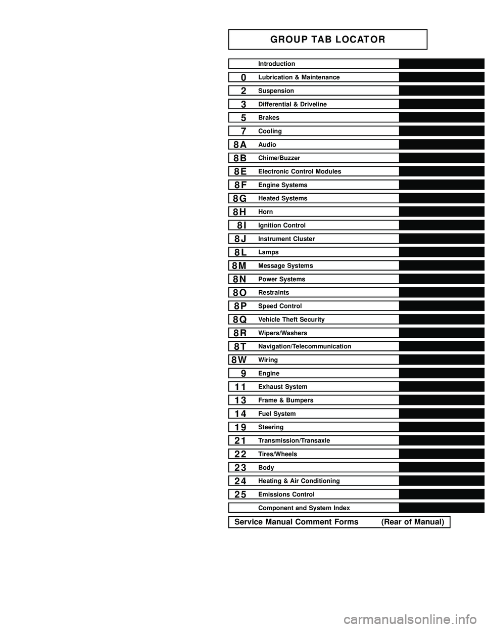
GROUP TAB LOCATOR
Introduction
0Lubrication & Maintenance
2Suspension
3Differential & Driveline
5Brakes
7Cooling
8AAudio
8BChime/Buzzer
8EElectronic Control Modules
8FEngine Systems
8GHeated Systems
8HHorn
8IIgnition Control
8JInstrument Cluster
8LLamps
8MMessage Systems
8NPower Systems
8ORestraints
8PSpeed Control
8QVehicle Theft Security
8RWipers/Washers
8TNavigation/Telecommunication
8WWiring
9Engine
11Exhaust System
13Frame & Bumpers
14Fuel System
19Steering
21Transmission/Transaxle
22Tires/Wheels
23Body
24Heating & Air Conditioning
25Emissions Control
Component and System Index
Service Manual Comment Forms (Rear of Manual)
Page 29 of 2339
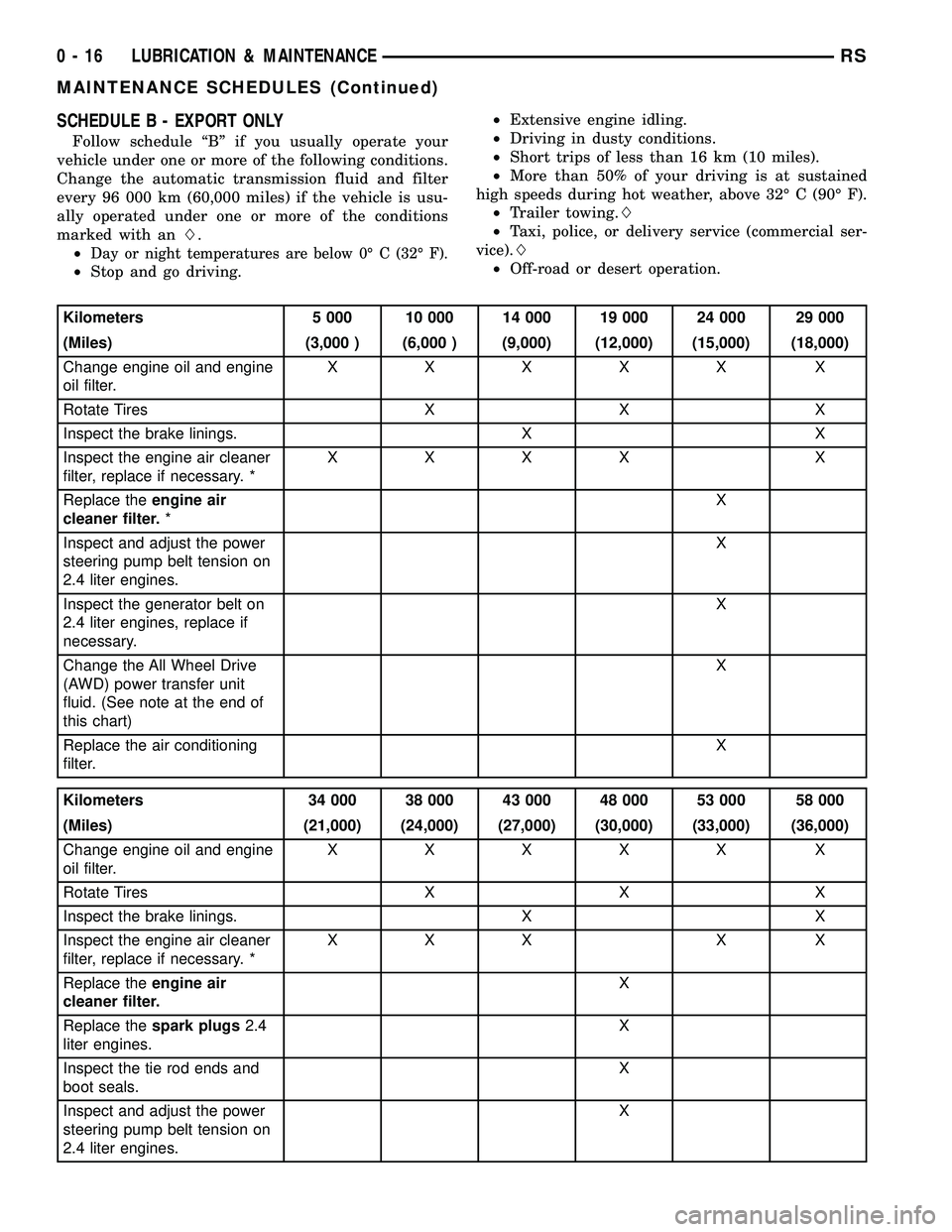
SCHEDULE B - EXPORT ONLY
Follow schedule ªBº if you usually operate your
vehicle under one or more of the following conditions.
Change the automatic transmission fluid and filter
every 96 000 km (60,000 miles) if the vehicle is usu-
ally operated under one or more of the conditions
marked with anL.
²
Day or night temperatures are below 0É C (32É F).
²Stop and go driving.²Extensive engine idling.
²Driving in dusty conditions.
²Short trips of less than 16 km (10 miles).
²More than 50% of your driving is at sustained
high speeds during hot weather, above 32É C (90É F).
²Trailer towing.L
²Taxi, police, or delivery service (commercial ser-
vice).L
²Off-road or desert operation.
Kilometers 5 000 10 000 14 000 19 000 24 000 29 000
(Miles) (3,000 ) (6,000 ) (9,000) (12,000) (15,000) (18,000)
Change engine oil and engine
oil filter.XXXXX X
Rotate Tires X X X
Inspect the brake linings. X X
Inspect the engine air cleaner
filter, replace if necessary. *XXXX X
Replace theengine air
cleaner filter.*X
Inspect and adjust the power
steering pump belt tension on
2.4 liter engines.X
Inspect the generator belt on
2.4 liter engines, replace if
necessary.X
Change the All Wheel Drive
(AWD) power transfer unit
fluid. (See note at the end of
this chart)X
Replace the air conditioning
filter.X
Kilometers 34 000 38 000 43 000 48 000 53 000 58 000
(Miles) (21,000) (24,000) (27,000) (30,000) (33,000) (36,000)
Change engine oil and engine
oil filter.XXXXX X
Rotate Tires X X X
Inspect the brake linings. X X
Inspect the engine air cleaner
filter, replace if necessary. *XXX X X
Replace theengine air
cleaner filter.X
Replace thespark plugs2.4
liter engines.X
Inspect the tie rod ends and
boot seals.X
Inspect and adjust the power
steering pump belt tension on
2.4 liter engines.X
0 - 16 LUBRICATION & MAINTENANCERS
MAINTENANCE SCHEDULES (Continued)
Page 30 of 2339
Kilometers 34 000 38 000 43 000 48 000 53 000 58 000
(Miles) (21,000) (24,000) (27,000) (30,000) (33,000) (36,000)
Inspect the generator belt on
2.4 liter engines, replace if
necessary.X
Inspect thePCV valveand
replace as necessary.*X
Change the manual
transmission fluid.X
Change the All Wheel Drive
(AWD) power transfer unit
fluid. (See note at the end of
this chart)X
Change the All Wheel Drive
(AWD) overrunning clutch and
rear carrier fluid. (See the
note at the end of this chart)X
Replace the air conditioning
filter.X
Kilometers 62 000 67 000 72 000 77 000 82 000 86 000
(Miles) (39,000) (42,000) (45,000) (48,000) (51,000) (54,000)
Change engine oil and engine
oil filter.XXXXX X
Rotate Tires X X X
Inspect the brake linings. X X
Inspect the engine air cleaner
filter, replace if necessary. *XX XX X
Replace theengine air
cleaner filter.*X
Inspect and adjust the power
steering pump belt tension on
2.4 liter engines.X
Inspect the generator belt on
2.4 liter engines, replace if
necessary.X
Change the manual
transmission fluid.X
Change the All Wheel Drive
power transfer unit fluid. (See
the note at the end of this chart.)X
Change the All Wheel Drive
(AWD) overrunning clutch and
rear carrier fluid. (See note at
the end of this chart)X
Replace the air conditioning
filter.X
RSLUBRICATION & MAINTENANCE0-17
MAINTENANCE SCHEDULES (Continued)
Page 31 of 2339
Kilometers 91 000 96 000 101 000 106 000 110 000 115 000
(Miles) (57,000) (60,000) (63,000) (66,000) (69,000) (72,000)
Change engine oil and engine
oil filter.XXXXX X
Rotate Tires X X X
Inspect the brake linings. X X
Inspect the engine air cleaner
filter, replace if necessary. *X XXX X
Replace theengine air
cleaner filter.X
Replace thespark plugson
2.4 liter engines.X
Replace theignition cables
on 2.4 liter engines.X
Inspect the tie rod ends and
boot seals.X
Inspect and adjust the power
steering pump belt tension on
2.4 liter engines.X
Inspect the generator belt on
2.4 liter engines, replace if
necessary.X
Inspect thePCV valveand
replace if necessary.*X
Inspect the serpentine drive
belt on 3.3 liter engines,
replace if necessary.X
Change the automatic
transmission fluid and filter.LX
Change the manual
transmission fluid.X
Change the All Wheel Drive
(AWD) power transfer unit
fluid. (See note at the end of
this chart)XX
Change the All Wheel Drive
(AWD) overrunning clutch and
rear carrier fluid. (See note at
the end of this chart)X
Replace the air conditioning
filter.X
0 - 18 LUBRICATION & MAINTENANCERS
MAINTENANCE SCHEDULES (Continued)
Page 32 of 2339
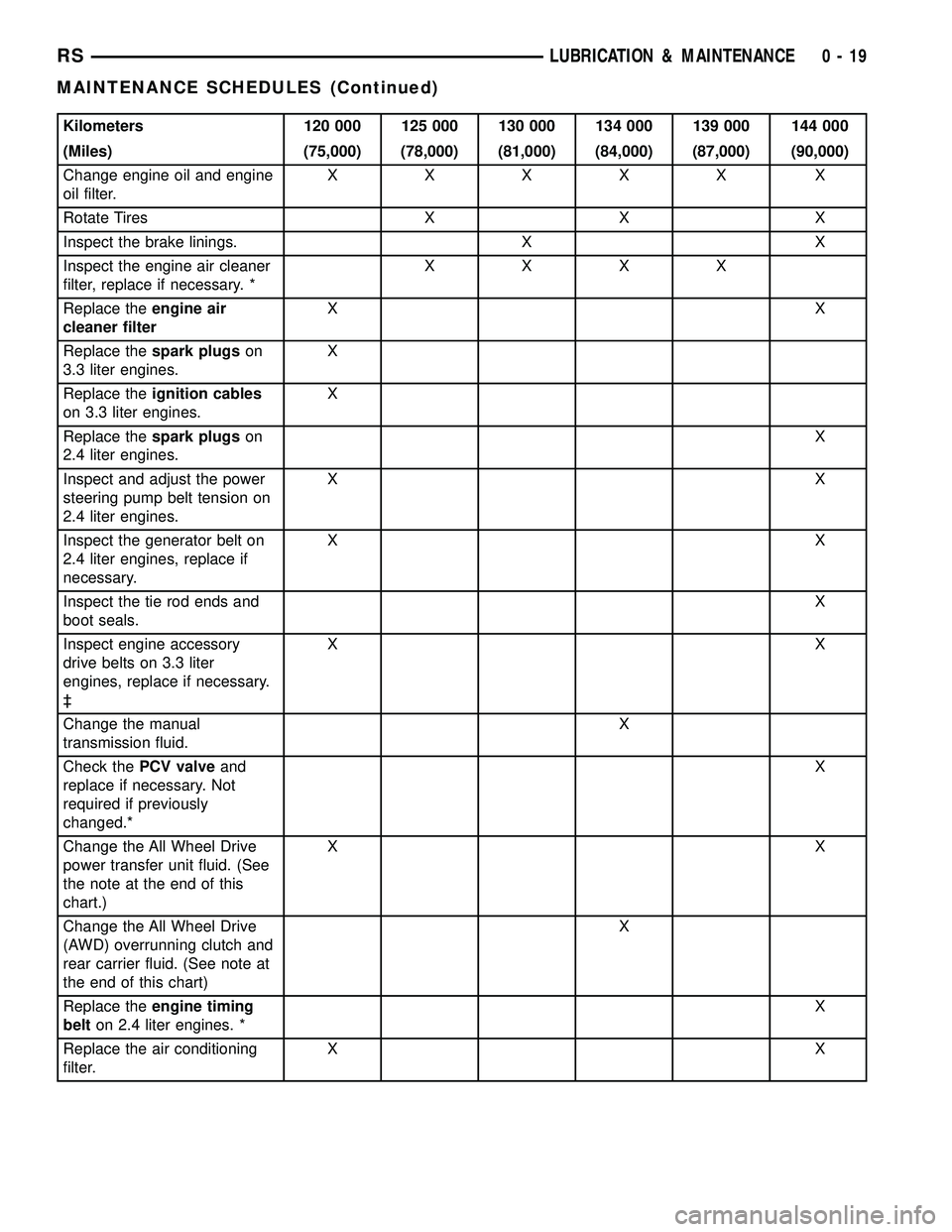
Kilometers 120 000 125 000 130 000 134 000 139 000 144 000
(Miles) (75,000) (78,000) (81,000) (84,000) (87,000) (90,000)
Change engine oil and engine
oil filter.XXXXX X
Rotate Tires X X X
Inspect the brake linings. X X
Inspect the engine air cleaner
filter, replace if necessary. *XXXX
Replace theengine air
cleaner filterXX
Replace thespark plugson
3.3 liter engines.X
Replace theignition cables
on 3.3 liter engines.X
Replace thespark plugson
2.4 liter engines.X
Inspect and adjust the power
steering pump belt tension on
2.4 liter engines.XX
Inspect the generator belt on
2.4 liter engines, replace if
necessary.XX
Inspect the tie rod ends and
boot seals.X
Inspect engine accessory
drive belts on 3.3 liter
engines, replace if necessary.
³XX
Change the manual
transmission fluid.X
Check thePCV valveand
replace if necessary. Not
required if previously
changed.*X
Change the All Wheel Drive
power transfer unit fluid. (See
the note at the end of this
chart.)XX
Change the All Wheel Drive
(AWD) overrunning clutch and
rear carrier fluid. (See note at
the end of this chart)X
Replace theengine timing
belton 2.4 liter engines. *X
Replace the air conditioning
filter.XX
RSLUBRICATION & MAINTENANCE0-19
MAINTENANCE SCHEDULES (Continued)
Page 33 of 2339
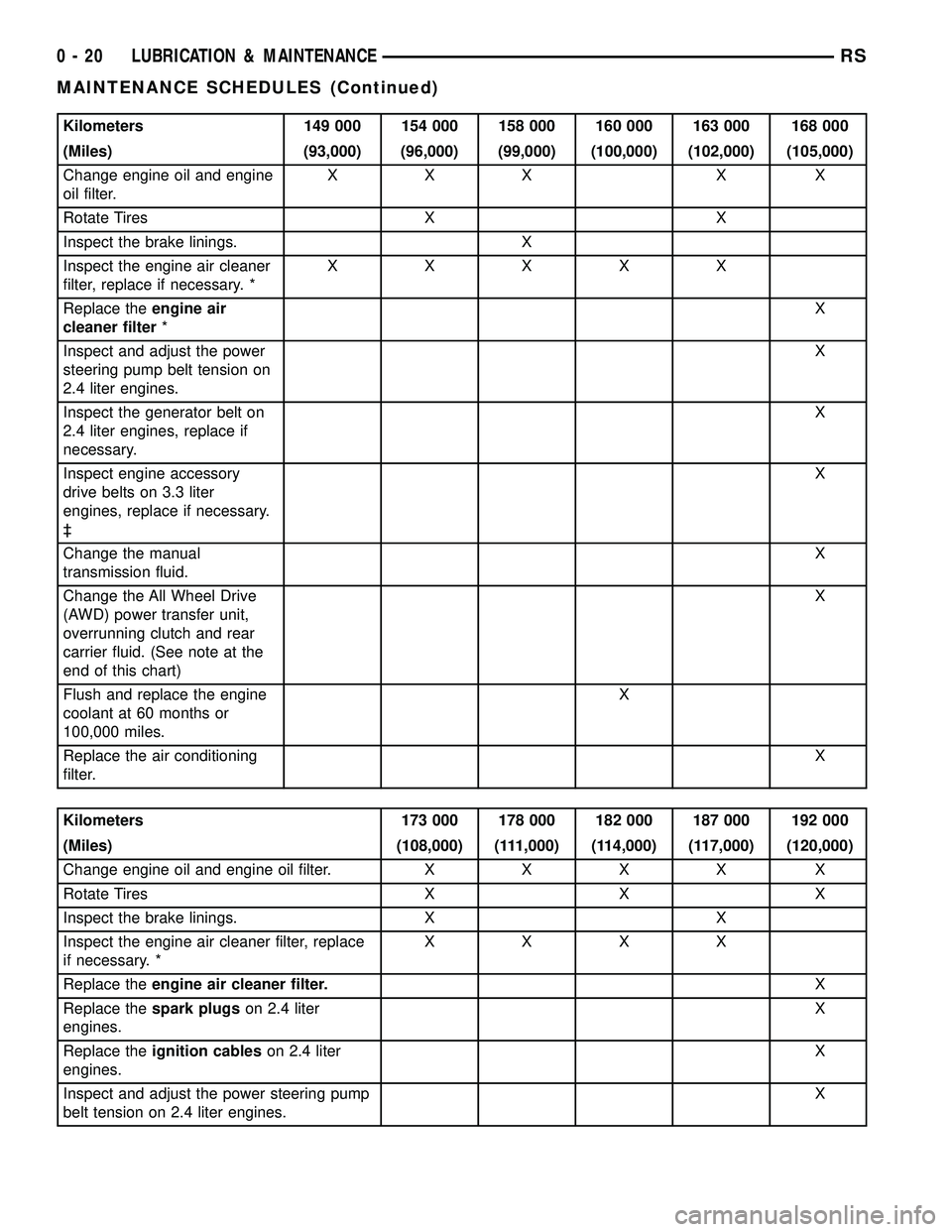
Kilometers 149 000 154 000 158 000 160 000 163 000 168 000
(Miles) (93,000) (96,000) (99,000) (100,000) (102,000) (105,000)
Change engine oil and engine
oil filter.XXX X X
Rotate Tires X X
Inspect the brake linings. X
Inspect the engine air cleaner
filter, replace if necessary. *XXXXX
Replace theengine air
cleaner filter*X
Inspect and adjust the power
steering pump belt tension on
2.4 liter engines.X
Inspect the generator belt on
2.4 liter engines, replace if
necessary.X
Inspect engine accessory
drive belts on 3.3 liter
engines, replace if necessary.
³X
Change the manual
transmission fluid.X
Change the All Wheel Drive
(AWD) power transfer unit,
overrunning clutch and rear
carrier fluid. (See note at the
end of this chart)X
Flush and replace the engine
coolant at 60 months or
100,000 miles.X
Replace the air conditioning
filter.X
Kilometers 173 000 178 000 182 000 187 000 192 000
(Miles) (108,000) (111,000) (114,000) (117,000) (120,000)
Change engine oil and engine oil filter.XXXX X
Rotate Tires X X X
Inspect the brake linings. X X
Inspect the engine air cleaner filter, replace
if necessary. *XXXX
Replace theengine air cleaner filter.X
Replace thespark plugson 2.4 liter
engines.X
Replace theignition cableson 2.4 liter
engines.X
Inspect and adjust the power steering pump
belt tension on 2.4 liter engines.X
0 - 20 LUBRICATION & MAINTENANCERS
MAINTENANCE SCHEDULES (Continued)
Page 39 of 2339
CAUTION: Do not crank starter motor on disabled
vehicle for more than 15 seconds, starter may over-
heat and could fail.
(7) If engine does not start within 15 seconds, stop
cranking engine and allow starter to cool (15 min-
utes), before cranking again.
DISCONNECT CABLE CLAMPS AS FOLLOWS:
²Disconnect BLACK cable clamp from engine
ground on disabled vehicle.
²When using a Booster vehicle, disconnect
BLACK cable clamp from battery negative terminal.
Disconnect RED cable clamp from battery positive
terminal.
²Disconnect RED cable clamp from battery posi-
tive terminal on disabled vehicle.
TOWING
STANDARD PROCEDURE - TOWING
WARNINGS AND CAUTIONS
WARNING: DO NOT ALLOW TOWING ATTACHMENT
DEVICES TO CONTACT THE FUEL TANK OR LINES,
FUEL LEAK CAN RESULT.
DO NOT LIFT OR TOW VEHICLE BY FRONT OR
REAR BUMPER.
DO NOT GO UNDER A LIFTED VEHICLE IF NOT
SUPPORTED PROPERLY ON SAFETY STANDS.
DO NOT ALLOW PASSENGERS TO RIDE IN A
TOWED VEHICLE.USE A SAFETY CHAIN THAT IS INDEPENDENT
FROM THE TOWING ATTACHMENT DEVICE.
CAUTION: Do not damage brake lines, exhaust sys-
tem, shock absorbers, sway bars, or any other
under vehicle components when attaching towing
device to vehicle.
Do not secure vehicle to towing device by the use
of front or rear suspension or steering components.
Remove or secure loose or protruding objects from
a damaged vehicle before towing.
Refer to state and local rules and regulations before
towing a vehicle.
Do not allow weight of towed vehicle to bear on
lower fascia, air dams, or spoilers.
RECOMMENDED TOWING EQUIPMENT
To avoid damage to bumper fascia and air dams
use:
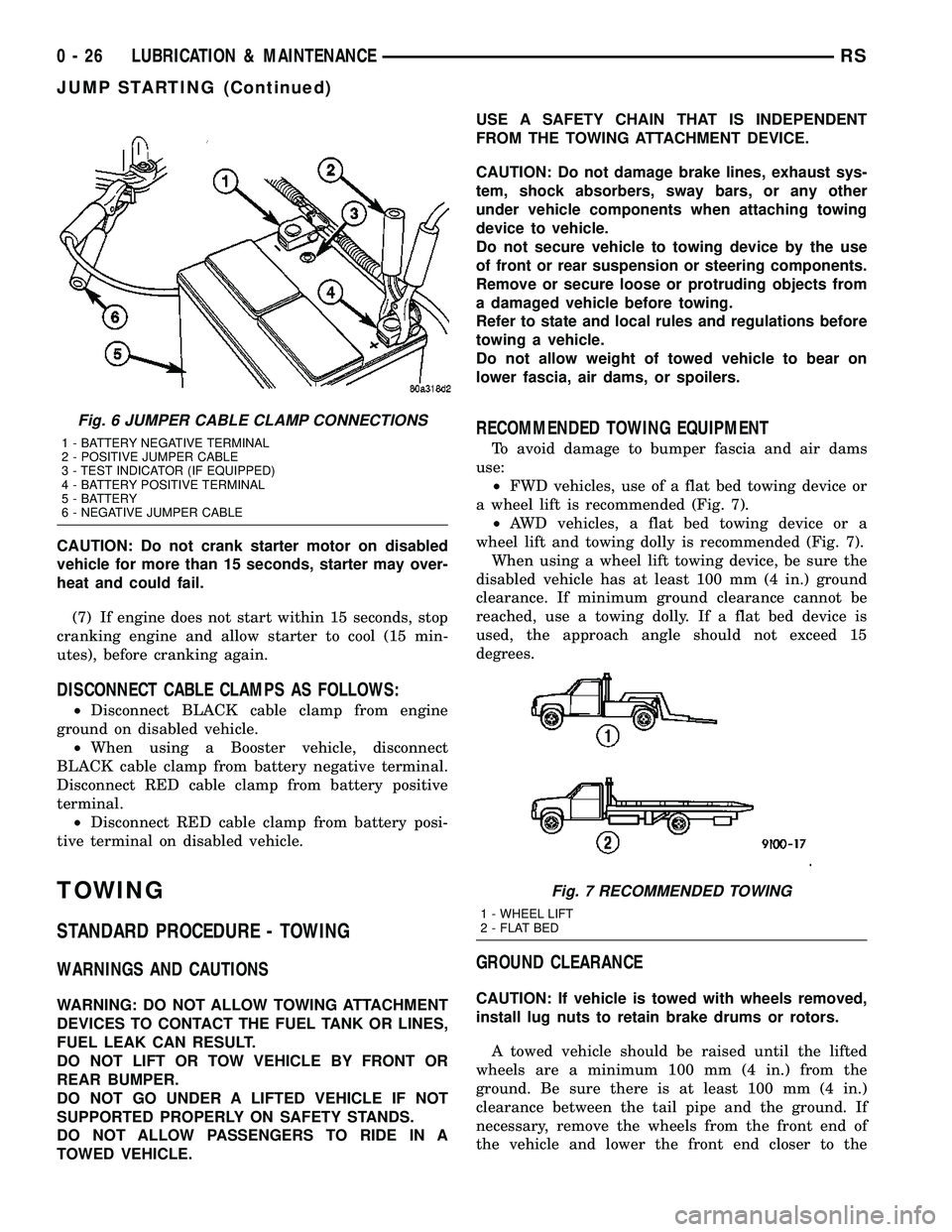
²FWD vehicles, use of a flat bed towing device or
a wheel lift is recommended (Fig. 7).
²AWD vehicles, a flat bed towing device or a
wheel lift and towing dolly is recommended (Fig. 7).
When using a wheel lift towing device, be sure the
disabled vehicle has at least 100 mm (4 in.) ground
clearance. If minimum ground clearance cannot be
reached, use a towing dolly. If a flat bed device is
used, the approach angle should not exceed 15
degrees.
GROUND CLEARANCE
CAUTION: If vehicle is towed with wheels removed,
install lug nuts to retain brake drums or rotors.
A towed vehicle should be raised until the lifted
wheels are a minimum 100 mm (4 in.) from the
ground. Be sure there is at least 100 mm (4 in.)
clearance between the tail pipe and the ground. If
necessary, remove the wheels from the front end of
the vehicle and lower the front end closer to the
Fig. 6 JUMPER CABLE CLAMP CONNECTIONS
1 - BATTERY NEGATIVE TERMINAL
2 - POSITIVE JUMPER CABLE
3 - TEST INDICATOR (IF EQUIPPED)
4 - BATTERY POSITIVE TERMINAL
5 - BATTERY
6 - NEGATIVE JUMPER CABLE
Fig. 7 RECOMMENDED TOWING
1 - WHEEL LIFT
2 - FLAT BED
0 - 26 LUBRICATION & MAINTENANCERS
JUMP STARTING (Continued)
Page 40 of 2339
ground, to increase the ground clearance at the rear
of the vehicle. Install lug nuts on wheel attaching
studs to retain brake drums or rotors.
LOCKED VEHICLE TOWING
When a locked vehicle must be towed with the
front wheels on the ground, use a towing dolly or flat
bed hauler.
FLAT TOWING WITH TOW BAR
²Three speed automatic transaxle vehicles can be
flat towed at speeds not to exceed 40 km/h (25 mph)
for not more than 25 km (15 miles). The steering col-
umn must be unlocked and gear selector in neutral.
²Four speed electronic automatic transaxle vehi-
cles can be flat towed at speeds not to exceed 72
km/h (44 mph) for not more than 160 km (100 miles).
The steering column must be unlocked and gear
selector in neutral.
²AWD models should not be flat towed. For addi-
tional information, refer toRECOMMENDED TOW-
ING EQUIPMENTin this section.
FLAT BED TOWING TIE DOWNS
CAUTION: Do not tie vehicle down by attaching
chains or cables to suspension components or
engine mounts, damage to vehicle can result.
The vehicle can be tied to a flat bed device using
the two pair of front slots on the bottom surface of
the rails, behind the front wheels. The two pair of
rear slots on the bottom of the rail between thebumper extension bolts and on the bottom of the rail
just rearward of the jounce bumper. Vehicles
equipped with a rear sway bar have brackets at this
location.
TOWING ± FRONT WHEEL LIFT
If the vehicle is being towed from the front, when-
ever possible ensure at least 10 inches road clearance
to the tires.
TOWING ± REAR WHEEL LIFT
If a vehicle cannot be towed with the front wheels
lifted, the rear wheels can be lifted provided the fol-
lowing guide lines are observed.
CAUTION: Do not use steering column lock to
secure steering wheel during towing operation.
²On AWD vehicles, all four wheels must be free to
rotate. Use towing dollies at unlifted end of vehicle.
²Unlock steering column and secure steering
wheel in straight ahead position with a clamp device
designed for towing.
²Three speed automatic transaxle vehicles can be
flat towed at speeds not to exceed 40 km/h (25 mph)
for not more than 25 km (15 miles). The steering col-
umn must be unlocked and gear selector in neutral.
²Four speed electronic automatic transaxle vehi-
cles can be flat towed at speeds not to exceed 72
km/h (44 mph) for not more than 160 km (100 miles).
The steering column must be unlocked and gear
selector in neutral.
RSLUBRICATION & MAINTENANCE0-27
TOWING (Continued)
Page 42 of 2339
SUSPENSION
TABLE OF CONTENTS
page page
FRONT SUSPENSION.....................1
REAR SUSPENSION......................26WHEEL ALIGNMENT.....................47
FRONT SUSPENSION
TABLE OF CONTENTS
page page
FRONT SUSPENSION
DESCRIPTION - FRONT SUSPENSION.......2
OPERATION - FRONT SUSPENSION.........2
STANDARD PROCEDURE - LUBRICATION....2
SPECIFICATIONS
FRONT SUSPENSION FASTENER TORQUE . . 3
SPECIAL TOOLS
FRONT SUSPENSION...................3
BUSHINGS
REMOVAL - STABILIZER BAR CUSHION......4
INSTALLATION - STABILIZER BAR CUSHION . . . 4
HUB / BEARING
DESCRIPTION..........................5
OPERATION............................5
DIAGNOSIS AND TESTING - HUB AND
BEARING............................5
REMOVAL.............................5
INSTALLATION..........................5
KNUCKLE
DESCRIPTION..........................6
OPERATION............................7
REMOVAL - STEERING KNUCKLE...........7
INSPECTION - STEERING KNUCKLE.........9
INSTALLATION - STEERING KNUCKLE.......9
LOWER BALL JOINT
DESCRIPTION.........................10
OPERATION...........................10
DIAGNOSIS AND TESTING - LOWER BALL
JOINT..............................10
LOWER BALL JOINT SEAL BOOT
DESCRIPTION - EXPORT.................10
REMOVAL
REMOVAL...........................11
REMOVAL - EXPORT...................11INSTALLATION
INSTALLATION.......................11
INSTALLATION - EXPORT...............11
LOWER CONTROL ARM
DESCRIPTION.........................12
OPERATION...........................12
REMOVAL - LOWER CONTROL ARM........12
DISASSEMBLY
DISASSEMBLY - LOWER CONTROL ARM
(REAR BUSHING - STANDARD)..........13
DISASSEMBLY - LOWER CONTROL ARM
(REAR BUSHING - HYDRO).............13
INSPECTION - LOWER CONTROL ARM......14
ASSEMBLY
ASSEMBLY - LOWER CONTROL ARM
(REAR BUSHING - STANDARD)..........14
ASSEMBLY - LOWER CONTROL ARM
(REAR BUSHING - HYDRO).............15
INSTALLATION - LOWER CONTROL ARM....15
STABILIZER BAR
DESCRIPTION.........................16
OPERATION...........................16
REMOVAL.............................17
INSPECTION..........................17
INSTALLATION.........................17
STRUT
DESCRIPTION - STRUT ASSEMBLY.........19
OPERATION - STRUT ASSEMBLY..........19
DIAGNOSIS AND TESTING - STRUT
ASSEMBLY..........................20
REMOVAL - STRUT ASSEMBLY............20
DISASSEMBLY - STRUT ASSEMBLY........21
ASSEMBLY - STRUT ASSEMBLY...........23
INSTALLATION - STRUT ASSEMBLY........25
RSSUSPENSION2-1
Page 43 of 2339
FRONT SUSPENSION
DESCRIPTION - FRONT SUSPENSION
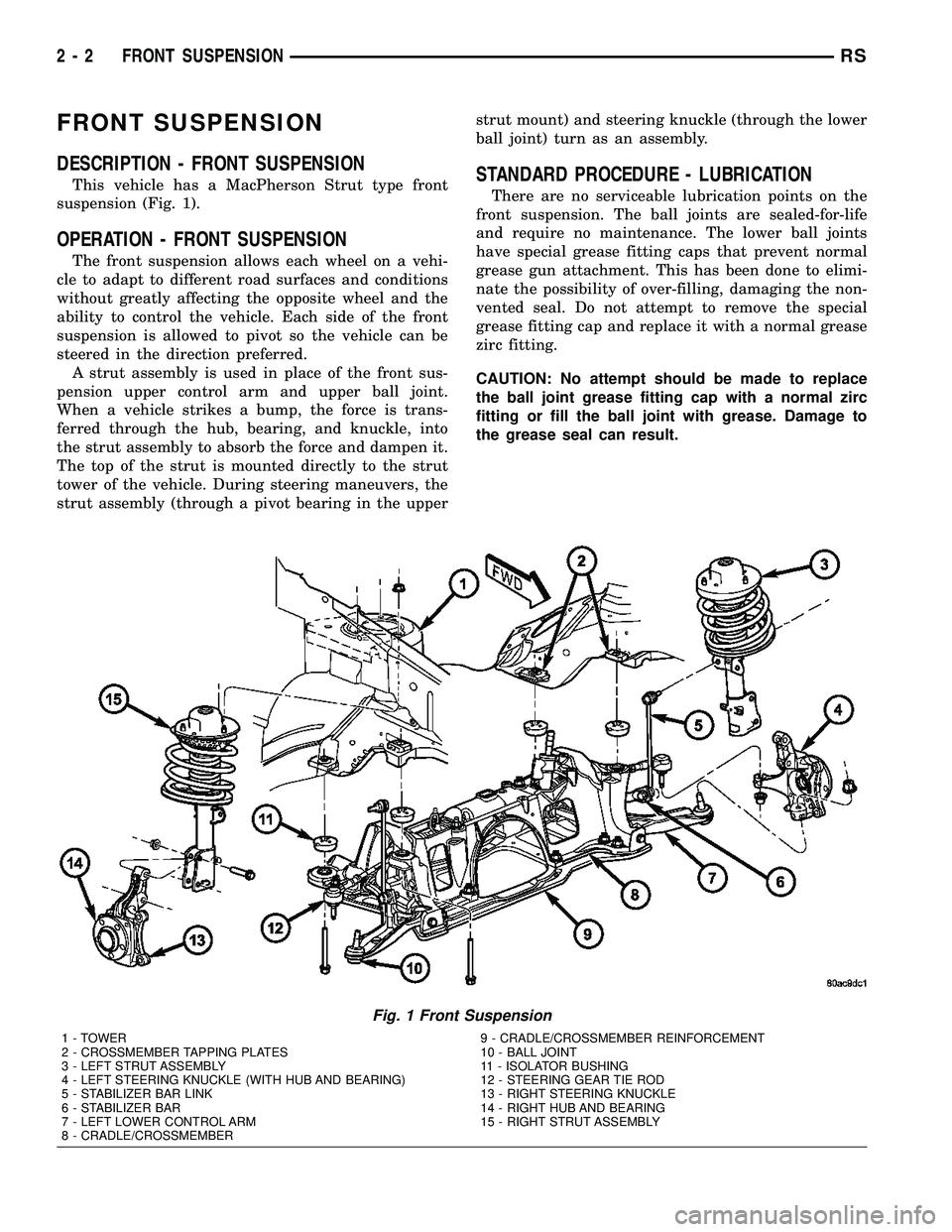
This vehicle has a MacPherson Strut type front
suspension (Fig. 1).
OPERATION - FRONT SUSPENSION
The front suspension allows each wheel on a vehi-
cle to adapt to different road surfaces and conditions
without greatly affecting the opposite wheel and the
ability to control the vehicle. Each side of the front
suspension is allowed to pivot so the vehicle can be
steered in the direction preferred.
A strut assembly is used in place of the front sus-
pension upper control arm and upper ball joint.
When a vehicle strikes a bump, the force is trans-
ferred through the hub, bearing, and knuckle, into
the strut assembly to absorb the force and dampen it.
The top of the strut is mounted directly to the strut
tower of the vehicle. During steering maneuvers, the
strut assembly (through a pivot bearing in the upperstrut mount) and steering knuckle (through the lower
ball joint) turn as an assembly.
STANDARD PROCEDURE - LUBRICATION
There are no serviceable lubrication points on the
front suspension. The ball joints are sealed-for-life
and require no maintenance. The lower ball joints
have special grease fitting caps that prevent normal
grease gun attachment. This has been done to elimi-
nate the possibility of over-filling, damaging the non-
vented seal. Do not attempt to remove the special
grease fitting cap and replace it with a normal grease
zirc fitting.
CAUTION: No attempt should be made to replace
the ball joint grease fitting cap with a normal zirc
fitting or fill the ball joint with grease. Damage to
the grease seal can result.
Fig. 1 Front Suspension
1 - TOWER
2 - CROSSMEMBER TAPPING PLATES
3 - LEFT STRUT ASSEMBLY
4 - LEFT STEERING KNUCKLE (WITH HUB AND BEARING)
5 - STABILIZER BAR LINK
6 - STABILIZER BAR
7 - LEFT LOWER CONTROL ARM
8 - CRADLE/CROSSMEMBER9 - CRADLE/CROSSMEMBER REINFORCEMENT
10 - BALL JOINT
11 - ISOLATOR BUSHING
12 - STEERING GEAR TIE ROD
13 - RIGHT STEERING KNUCKLE
14 - RIGHT HUB AND BEARING
15 - RIGHT STRUT ASSEMBLY
2 - 2 FRONT SUSPENSIONRS