radio controls CHRYSLER CARAVAN 2005 Service Manual
[x] Cancel search | Manufacturer: CHRYSLER, Model Year: 2005, Model line: CARAVAN, Model: CHRYSLER CARAVAN 2005Pages: 2339, PDF Size: 59.69 MB
Page 277 of 2339
SPEAKER
DIAGNOSIS AND TESTING
SPEAKER
WARNING: DISABLE THE AIRBAG SYSTEM
BEFORE ATTEMPTING ANY STEERING WHEEL,
STEERING COLUMN, SEAT BELT TENSIONER, SIDE
AIRBAG, OR INSTRUMENT PANEL COMPONENT
DIAGNOSIS OR SERVICE. DISCONNECT AND ISO-
LATE THE BATTERY NEGATIVE (GROUND) CABLE,
THEN WAIT TWO MINUTES FOR THE AIRBAG SYS-
TEM CAPACITOR TO DISCHARGE BEFORE PER-
FORMING FURTHER DIAGNOSIS OR SERVICE. THIS
IS THE ONLY SURE WAY TO DISABLE THE AIRBAG
SYSTEM. FAILURE TO TAKE THE PROPER PRE-
CAUTIONS COULD RESULT IN ACCIDENTAL AIR-
BAG DEPLOYMENT AND POSSIBLE PERSONAL
INJURY.
Any diagnosis of the Audio system should
begin with the use of the DRB IIItdiagnostic
tool. For information on the use of the DRB
IIIt, refer to the appropriate Diagnostic Service
Manual.
(1) If all speakers are inoperative, check the radio
fuses in the Junction Block (JB). If OK, go to Step 2.
If not OK, repair the shorted circuit or component as
required and replace the faulty fuse.
(2) Check the amplifier fuse (if equipped) in the
junction block. If OK, go to Step 3. If not OK, repair
the shorted circuit or component as required and
replace the faulty fuse.
(3) Turn the ignition switch to the ON position.
Turn the radio receiver ON. Adjust the balance and
fader control controls to check the performance of
each individual speaker. Note the speaker locations
that are not performing correctly. Go to Step 4.
(4) Turn the radio receiver OFF. Turn the ignition
OFF. Disconnect and isolate the battery negative
cable. If vehicle isnotequipped with a amplifier,
remove the radio receiver. If vehicle is equipped with
an amplifier. disconnect wire harness connector at
output side of amplifier. Go to Step 4.
(5) Check both the speaker feed (+) circuit and
return (-) circuit cavities for the inoperative speaker
at the radio receiver wire harness connector for con-
tinuity to ground. There should be no continuity. If
OK, go to Step 5. If not OK, repair the shorted
speaker feed (+) and/or return (-) circuits(s) to the
speaker as required.(6) Disconnect wire harness connector at the inop-
erative speaker. Check for continuity between the
speaker feed (+) circuit cavities of the radio receiver
wire harness connector or if equipped, the amplifier
wire harness connector and the speaker wire harness
connector. Repeat the check between the speaker
return (-) circuit cavities of the radio receiver wire
harness connector and the speaker wire harness con-
nector. In each case, there should be continuity. If
OK, replace the faulty speaker. If not OK, repair the
open speaker feed (+) and/or return (-) circuits(s) as
required.
REMOVAL
D-PILLAR SPEAKER
(1) Disconnect and isolate the battery negative
cable.
(2) Remove rear header trim (right side speaker).
(3) Remove jack cover (left side speaker).
(4) Remove liftgate scuff plate.
(5) Remove upper seat belt bolt. (Refer to 8 -
ELECTRICAL/RESTRAINTS/SEAT BELT OUT-
BOARD FRONT - REMOVAL).
(6) Partially remove quarter trim panel to access
the D-pillar speaker.
(7) Slide the speaker from the retainer (Fig. 17).
(8) Disconnect the wire harness connector from the
speaker.
Fig. 17 D-PILLAR SPEAKER
1 - SPEAKER
2 - RETAINER
3 - TRIM PANEL
8A - 18 AUDIO/VIDEORS
Page 288 of 2339
The BCM utilizes integrated circuitry and informa-
tion carried on the Programmable Communications
Interface (PCI) data bus network along with many
hard wired inputs to monitor many sensor and
switch inputs throughout the vehicle. In response to
those inputs, the internal circuitry and programming
of the BCM allow it to control and integrate many
electronic functions and features of the vehicle
through both hard wired outputs and the transmis-
sion of electronic message outputs to other electronic
modules in the vehicle over the PCI data bus.
OPERATION
The Body Control Module (BCM) supplies vehicle
occupants with visual and audible information and
controls various vehicle functions. To provide and
receive information, the BCM is interfaced to the
vehicle's serial bus communications network, referred
to as the Programmable Communications Interface
(PCI) bus.
This network consists of the;
²Powertrain Control Module (PCM)
²Transmission Control Module (TCM)
²Mechanical Instrument Cluster (MIC)
²Occupant Restraint Controller (ORC)
²Compass/Mini-Trip Computer (CMTC)
²Electronic Vehicle Information Center (EVIC)
²Controller Antilock Brake (CAB)
²HVAC Control Module
²Sliding Door Control Modules (driver and pas-
senger side doors)
²Power Liftgate Module (PLG)
²Audio system equipped with RAZ, RBU, RBK,
and RBB radios.
²Sentry Key Remote Entry Module (SKREEM).
²Side Impact Airbag Control Module (SIACM)²Memory Seat Module (MSM)
²Sentry Key Immobilizer Module (SKIM)
The BCM is operational when battery power is
supplied to the module.
The BCM provides the following features:
²Power Door Locks
²Automatic Door Locks
²Battery Protection - The BCM will automatically
turn off all exterior lamps after 3 minutes, and all
interior lamps after 15 minutes after the ignition is
turned off, if they are not turned off by the driver.
²Chime Control
²Compass/Mini-Trip support.
²Interior Lighting (Courtesy/Reading Lamps)
²BCM Diagnostic Reporting
²Electronic Liftgate Release (with Power Door
Locks)
²Exterior Lighting
²Headlamp Time Delay (with/without Automatic
Headlamps)
²Illuminated Entry
²Fade to Off Interior Lamps - This feature dims
the interior lighting (courtesy lamps) gradually if the
BCM does not receive any new inputs that would
cause the interior lamps to remain on.
²Pulse Width Modulated Instrument Panel Dim-
ming
²Door Lock Inhibit - This feature disables the
door lock functions if the key is in the ignition and
either front door is ajar. Pressing the Remote Keyless
Entry (RKE) lock/unlock button under these condi-
tions result in normal lock/unlock activation.
The BCM has the ability to LEARN additional fea-
tures in the vehicle, provided the appropriate switch
input and PCI data bus messages are received. Refer
to the LEARNED FEATURES table.
LEARNED FEATURES
FEATURE LEARNING KEY
REAR WIPER CONTROL ON HVAC CONTROL ON
INSTRUMENT PANELPCI BUS MESSAGE RECEIVED FROM HVAC
CONTROL
AUTOMATIC HEADLAMPS PCI MESSAGE FROM OVERHEAD OR HEADLAMP
SWITCH POSITION (AUTO)
REMOTE KEYLESS ENTRY SKREEM MESSAGE RECEIVED FROM MODULE
FRONT FOG LAMPS HEADLAMP SWITCH POSITION (PARK W/FRONT
FOG LAMPS)
POWER SLIDING DOOR PCI IFR RECEIVED FROM MODULE
THE BCM HAS FOUR SWITCH INPUTS FOR THE POWER SLIDING DOOR FEATURE; LOCATED IN THE
OVERHEAD CONSOLE ARE THE LEFT AND RIGHT SIDE SLIDING DOOR SWITCHES TO ACTIVATE EITHER
OR BOTH SLIDING DOORS UNDER THE PROPER CONDITIONS. ALSO ARE B-PILLAR SWITCHES LOCATED
ON THE LEFT AND RIGHT B-PILLAR POSTS.
POWER LIFTGATE PCI IFR RECEIVED FROM MODULE
RSELECTRONIC CONTROL MODULES8E-3
BODY CONTROL MODULE (Continued)
Page 289 of 2339
FEATURE LEARNING KEY
THE BCM HAS ONE LIFTGATE INPUT LOCATED IN THE OVERHEAD CONSOLE.
POWER LOCKOUT SWITCH INPUT
THE BCM HAS ONE LOCKOUT SWITCH INPUT THAT WHEN ENABLED WILL DISABLE THE B-PILLAR
SLIDING DOOR SWITCHES FROM ACTIVATING EITHER SLIDING DOOR WHEN DEPRESSED.
PCI AUDIO SYSTEM PCI MESSAGE RECEIVED FROM MODULE
REMOTE RADIO CONTROLS REMOTE RADIO SWITCHES PRESENT
VEHICLE THEFT SECURITY SKREEM MESSAGE RECEIVED, VALID KEY
RECEIVED, & DIAGNOSTIC PID RECEIVED.
MEMORY SEAT AND MIRRORS MEMORY SEAT SWITCH PRESENT AND OR PCI
MESSAGE RECEIVED FROM MEMORY MODULE
ABS W/TRACTION CONTROL PCI MESSAGE RECEIVED FROM CAB
SENTRY KEY IMMOBILIZER SYSTEM PCI MESSAGE RECEIVED FROM SKIM OR VTSS
PRESENT
ADJUSTABLE PEDAL MODULE PCI MESSAGE RECEIVED FROM ADJUSTABLE
PEDAL MODULE (APM)
When replacing a BCM there are three modules
available:
²Base
²Midline
²RG - Export
The Midline controller is used on vehicles that
have Power Door Locks. If a vehicle is equipped with
the Vehicle Theft Security System, the Midline con-
troller becomes a Premium when the theft feature is
enabled.
CAUTION: Do not swap Body Control Modules
between vehicles or body controller's off the shelf.
The BCM has internal diagnostic capability that
assists in diagnosing the system error. When an
OPEN or a SHORT circuit exists, the diagnostic tool
can be used to read the BCM faults. The faults are
very descriptive in identifying the appropriate fea-
ture that has faulted.
The only two faults that the BCM logs that con-
clude the replacement of a BCM are faults;
²# 01 - Internal BCM failure (replace BCM)
²# 1F - J1850 Internal Hardware Failure (replace
BCM)
Otherwise the appropriate diagnostic procedures
for each of the features should be taken when the
BCM logs a fault.
REMOVAL
(1) Disconnect and isolate the battery negative
cable.
(2) Remove the lower instrument panel silencer.(3) Remove the knee blocker and reinforcement
(Refer to 23 - BODY/INSTRUMENT PANEL/KNEE
BLOCKER REINFORCEMENT - REMOVAL).
(4) Disconnect the five wire connectors from the
bottom of the Body Control Module (BCM).
(5) Move bulkhead wiring aside.
(6) Remove the screws holding the BCM to the
bulkhead.
(7) Remove the BCM from the mounting bracket.
INSTALLATION
(1) Install the BCM to the mounting bracket.
(2) Install the screws holding the BCM to the
bulkhead.
(3) Connect the five wire connectors to the bottom
of the Body Control Module (BCM).
(4) Install the knee blocker and reinforcement
(Refer to 23 - BODY/INSTRUMENT PANEL/KNEE
BLOCKER REINFORCEMENT - INSTALLATION).
(5) Install the lower instrument panel silencer.
(6) Connect the battery negative cable.
(7) Verify proper operation of BCM and its func-
tions.
CONTROLLER ANTILOCK
BRAKE
DESCRIPTION
The controller antilock brake (CAB) is a micropro-
cessor-based device which monitors the antilock
brake system (ABS) during normal braking and con-
trols it when the vehicle is in an ABS stop. The CAB
is mounted to the HCU as part of the integrated con-
trol unit (ICU) (Fig. 1). The CAB uses a 24-way elec-
8E - 4 ELECTRONIC CONTROL MODULESRS
BODY CONTROL MODULE (Continued)
Page 292 of 2339
FRONT CONTROL MODULE
DESCRIPTION
The Front Control Module (FCM) is a micro con-
troller based module located in the engine compart-
ment. The FCM mates to the Power Distribution
Center (PDC) to form the Integrated Power Module
(IPM). The IPM connects directly to the battery and
provides the primary means of circuit protection and
power distribution for all vehicle electrical systems.
The FCM controls power to some of these vehicle sys-
tems electrical and electromechanical loads based on
inputs received from hard wired switch inputs and
data received on the Programmable Communications
Interface (PCI) data bus.
For information on the IPM, (Refer to 8 - ELEC-
TRICAL/POWER DISTRIBUTION/INTEGRATED
POWER MODULE - DESCRIPTION)
OPERATION
As messages are sent over the Programmable Com-
munications Interface (PCI) data bus, the Front Con-
trol Module (FCM) reads these messages and controls
power to some of the vehicles electrical systems by
completing the circuit to ground (low side driver) or
completing the circuit to 12 volt power (high side
driver).
The following functions arecontrolledby the
Front Control Module:
²Accessory Relay Actuation
²Brake Transmission Shift Interlock Functions
(BTSI - gas engine only)
²Diesel Cabin Heater (Diesel Engine Vehicles)
²Electronic Back Light (EBL) Rear Defogger
²Front and Rear Blower Motor Relay Actuation
²Front Fog Lamp Relay Actuation
²Washer Motor (front and rear)
²Front Windshield Wiper ªHIº & ªLOº Relay
Actuation
²Front Windshield Wiper ªONº Relay Actuation
²Headlamp Power with Voltage Regulation
²Horn Relay Actuation
²Headlamp Washer Relay Actuation (IF
EQUIPPED - EXPORT ONLY)
²Name Brand Speaker (NBS) Relay Actuation
²Park Lamp Relay Actuation
The following inputs areReceived/Monitoredby
the Front Control Module:
²Ambient Temperature Sensing
²Back-Up switch
²Brake Fluid Level
²B+ Connection Detection
²Engine Crank Signal (Diesel Engine Vehicles)
²Horn Input
²Ignition Switch Start Only
²Ignition Switch Run and Start Only²Stop Lamp Sense
²Washer Fluid Level
²Windshield Wiper Park
DIAGNOSIS AND TESTING
FRONT CONTROL MODULE
The Front Control Module (FCM) is a printed cir-
cuit board based module with a on-board micro-pro-
cessor. The FCM interfaces with other electronic
modules in the vehicle via the Programmable Com-
munications Interface (PCI) data bus. In order to
obtain conclusive testing the PCI data bus and all of
the electronic modules that provide inputs to, or
receive outputs from the FCM must be checked. All
PCI communication faults must be resolved prior to
further diagnosing any front control module related
issues.
The FCM was designed to be diagnosed with an
appropriate diagnostic scan tool, such as the DRB
IIIt. The most reliable, efficient, and accurate means
to diagnose the front control module requires the use
of a DRB IIItscan tool and the proper Body Diag-
nostic Procedures manual.
Before any testing of the FCM is attempted, the
battery should be fully charged and all wire harness
and ground connections inspected around the affected
areas on the vehicle.
REMOVAL
(1) Disconnect and isolate the negative and posi-
tive battery cables from the battery.
(2) Remove the battery (Refer to 8 - ELECTRI-
CAL/BATTERY SYSTEM/BATTERY - REMOVAL).
(3) Using a long flat-bladed screwdriver, gently
twist the Integrated Power Module (IPM) retaining
clip outboard to free the IPM from its mounting
bracket (Fig. 5). Rotate IPM upward to access the
Front Control Module (FCM) retaining screws.
(4) Remove the front control module retaining
screws.
(5) Pull the FCM straight from the IPM assembly
to disconnect the electrical connector (Fig. 6) and
remove the FCM from the vehicle.
INSTALLATION
NOTE: Front Control Module must be programmed
to the correct radio EQ curve using the DRB IIIT.
This will ensure that the audio system is operating
correctly.
(1) Install the Front Control Module (FCM) in the
Integrated Power Module (IPM) assembly by pushing
the 49-way electrical connector straight in.
RSELECTRONIC CONTROL MODULES8E-7
Page 293 of 2339

(2) Install the FCM retaining screws. Torque the
screws to 1 N´m (7 in. lbs).
(3) Rotate the IPM assembly downward to secure
in mounting bracket.
(4) Install the battery in the vehicle. Refer to the
procedure in Battery Systems.
(5) Connect the positive and negative battery
cables.(6) Using the DRB IIIt, under ªFRONT CON-
TROL MODULEº then ªMISCº program the EQ
curve of the radio into the Front Control Module.
Refer to the appropriate diagnostic manual.
NOTE: If the vehicle is not equipped with Name
Brand Speakers (Infinity, etc.) or Headlamp Washers
the DRB IIITmust be used to Disable the appropri-
ate relays in the Integrated Power Module Assem-
bly.
HEATED SEAT MODULE
DESCRIPTION
Vehicles equipped with heated seats utilize two
heated seat modules. The heated seat modules are
located under the front seats, where they are secured
to the seat cushion pans. Each heated seat module
has three connector receptacles that allow the mod-
ules to be connected to all of the required inputs and
outputs through the seat wire harness.
The heated seat modules are an electronic micro-
processor controlled device designed and programmed
to use inputs from the ignition switch, heated seat
switch and the heated seat sensor to operate and
control the heated seat elements in the front seat.
OPERATION
The heated seat module operates on fused battery
current received from the Integrated Power Module
(IPM). The module is grounded at all times through
the seat wire harness. Inputs to the module include a
resistor multiplexed heated seat switch request cir-
cuit for the heated seat switch and the heated seat
sensor inputs from the seat cushions of each front
seat. In response to those inputs the heated seat
module controls battery current feeds to the heated
seat elements.
When a heated seat switch request signal is
received by the heated seat module and the enable
input is high, the heated seat module energizes the
selected heated seat sensor circuit and the sensor
provides the module with an input indicating the
surface temperature of the selected seat cushion.
The Low heat set point is approximately 35É C (95É
F), and the High heat set point is approximately 40É
C (104É F). If the seat cushion surface temperature
input is below the temperature set point for the
selected temperature setting, the heated seat module
energizes an N-channel Field Effect Transistor
(N-FET) within the module which energizes the
heated seat elements in the selected seat cushion and
back. When the sensor input to the module indicates
the correct temperature set point has been achieved,
the module de-energizes the N-FET which de-ener-
Fig. 5 REMOVING INTEGRATED POWER MODULE
Fig. 6 FRONT CONTROL MODULE
1 - FRONT CONTROL MODULE
8E - 8 ELECTRONIC CONTROL MODULESRS
FRONT CONTROL MODULE (Continued)
Page 420 of 2339
NOTE: If a new CMTC module has been installed,
the compass will have to be calibrated and the vari-
ance set. (Refer to 8 - ELECTRICAL/OVERHEAD
CONSOLE - STANDARD PROCEDURE - COMPASS
CALIBRATION).
UNIVERSAL TRANSMITTER
DESCRIPTION
A Universal Transmitter transceiver is available on
some vehicles. The universal transmitter transceiver
is integral to the Electronic Vehicle Information Cen-
ter (EVIC) and the Compass Mini-Trip Computer
(CMTC) modules, which are located in the overhead
console. The only visible component of the universal
transmitter are the three transmitter push buttons
centered between the modules push buttons located
just rearward of the display screen in the overhead
console. The three universal transmitter push but-
tons are identified with one, two or three light indi-
cators so that they can be easily identified.
Each of the three universal transmitter push but-
tons controls an independent radio transmitter chan-
nel. Each of these three channels can be trained to
transmit a different radio frequency signal for the
remote operation of garage door openers, motorized
gate openers, home or office lighting, security sys-
tems or just about any other device that can be
equipped with a radio receiver in the 286 to 399
MegaHertz (MHz) frequency range for remote opera-
tion. The universal transmitter is capable of operat-
ing systems using either rolling code or non-rolling
code technology.
The electronics module displays messages and a
small house-shaped icon with one, two or three dots
corresponding to the three transmitter buttons to
indicate the status of the universal transmitter. The
EVIC messages are:
²Cleared Channels- Indicates that all of the
transmitter codes stored in the universal transmitter
have been successfully cleared.
²Training- Indicates that the universal trans-
mitter is in its transmitter learning mode.
²Trained- Indicates that the universal transmit-
ter has successfully acquired a new transmitter code.
²Transmit- Indicates that a trained universal
transmitter button has been depressed and that the
universal transmitter is transmitting.
The universal transmitter cannot be repaired, and
is available for service only as a unit with the EVIC
or CMTC modules. If any of these components is
faulty or damaged, the complete EVIC or CMTC
module must be replaced.
DIAGNOSIS AND TESTING
UNIVERSAL TRANSMITTER
If both the Universal Transmitter and the Elec-
tronic Vehicle Information Center (EVIC) are inoper-
ative, (Refer to 8 - ELECTRICAL/OVERHEAD
CONSOLE/ELECTRONIC VEHICLE INFO CENTER
- DIAGNOSIS AND TESTING). If the Universal
Transmitter is inoperative, but the EVIC is operating
normally, retrain the Transmitter with a known good
transmitter (Refer to 8 - ELECTRICAL/OVERHEAD
CONSOLE/UNIVERSAL TRANSMITTER - STAN-
DARD PROCEDURE - SETTING TRANSMITTER
CODES). If the unit is still inoperative, test the uni-
versal transmitter with the Radio Frequency Detec-
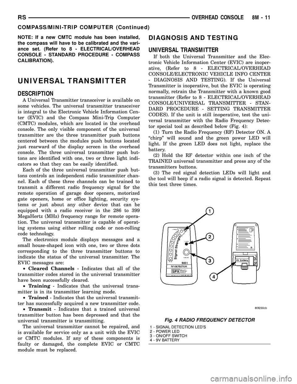
tor special tool as described below (Fig. 4):
(1) Turn the Radio Frequency (RF) Detector ON. A
ªchirpº will sound and the green power LED will
light. If the green LED does not light, replace the
battery.
(2) Hold the RF detector within one inch of the
TRAINED universal transmitter and press any of the
transmitters buttons.
(3) The red signal detection LEDs will light and
the tool will beep if a radio signal is detected. Repeat
this test three times.
Fig. 4 RADIO FREQUENCY DETECTOR
1 - SIGNAL DETECTION LED'S
2 - POWER LED
3 - ON/OFF SWITCH
4 - 9V BATTERY
RSOVERHEAD CONSOLE8M-11
COMPASS/MINI-TRIP COMPUTER (Continued)
Page 505 of 2339
INSTALLATION
DEPLOYED AIRBAG
(1) Perform clean up procedure (Refer to 8 - ELEC-
TRICAL/RESTRAINTS - STANDARD PROCEDURE
- SERVICE AFTER AN AIRBAG DEPLOYMENT).
(2) Install a new steering column assembly and
lower steering column coupler (Refer to 19 - STEER-
ING/COLUMN - INSTALLATION).
(3) Install the new clockspring.
(4) Connect the 4-way and 6-way connectors
between the clockspring and the instrument panel
wiring harness.
(5) Install the steering column shrouds and con-
nect traction control wire connector (if equipped)
(Refer to 19 - STEERING/COLUMN/LOWER
SHROUD - INSTALLATION).
(6) Install the steering wheel (Refer to 19 -
STEERING/COLUMN/STEERING WHEEL -
INSTALLATION).
(7) Connect the 4±way harness connector to the
speed control/horn harness to the clockspring.
(8) Connect the 2±way connector to the remote
radio control harness.
(9) Install the driver airbag and the two screws
retaining the airbag. Tighten screws to 10 N´m (90
in. lbs.)
WARNING: Do not connect the battery negative
cable (Refer to 8 - ELECTRICAL/RESTRAINTS -
DIAGNOSIS AND TESTING - AIRBAG SYSTEM). Per-
sonal injury or death may result if the system test
is not performed first.
UNDEPLOYED AIRBAG
(1) Connect the harness connector on the driver
airbag trim cover (horn, speed controls) to the clock-
spring.
(2) Connect the squib connectors to the driver air-
bag.
(3) Position the driver airbag into the steering
wheel.
(4) Install the two screws retaining the airbag.
Tighten screws to 10 N´m (90 in. lbs.)
WARNING: Do not connect the battery negative
cable (Refer to 8 - ELECTRICAL/RESTRAINTS -
DIAGNOSIS AND TESTING - AIRBAG SYSTEM). Per-
sonal injury or death may result if the system test
is not performed first.
IMPACT SENSOR
DESCRIPTION
FRONT IMPACT SENSORS
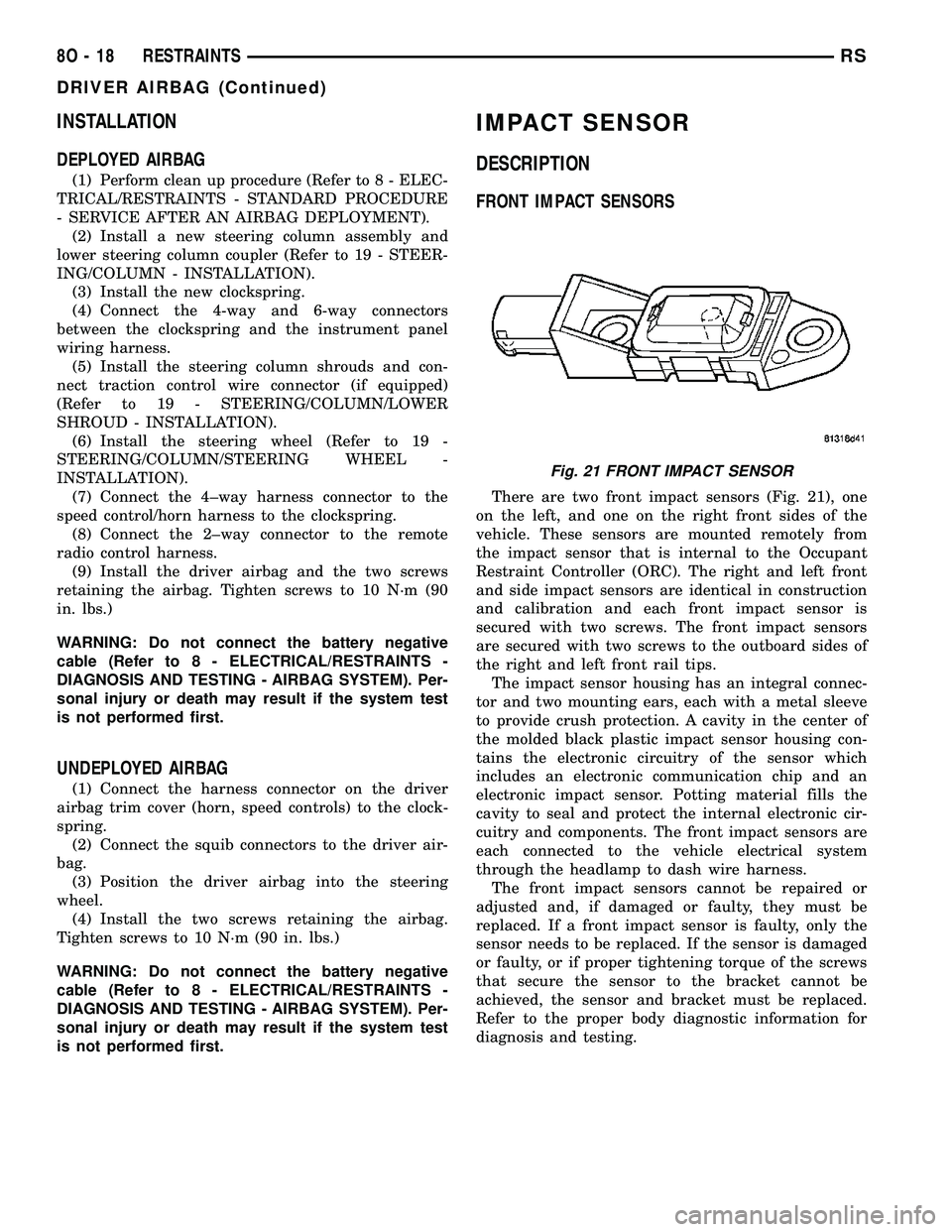
There are two front impact sensors (Fig. 21), one
on the left, and one on the right front sides of the
vehicle. These sensors are mounted remotely from
the impact sensor that is internal to the Occupant
Restraint Controller (ORC). The right and left front
and side impact sensors are identical in construction
and calibration and each front impact sensor is
secured with two screws. The front impact sensors
are secured with two screws to the outboard sides of
the right and left front rail tips.
The impact sensor housing has an integral connec-
tor and two mounting ears, each with a metal sleeve
to provide crush protection. A cavity in the center of
the molded black plastic impact sensor housing con-
tains the electronic circuitry of the sensor which
includes an electronic communication chip and an
electronic impact sensor. Potting material fills the
cavity to seal and protect the internal electronic cir-
cuitry and components. The front impact sensors are
each connected to the vehicle electrical system
through the headlamp to dash wire harness.
The front impact sensors cannot be repaired or
adjusted and, if damaged or faulty, they must be
replaced. If a front impact sensor is faulty, only the
sensor needs to be replaced. If the sensor is damaged
or faulty, or if proper tightening torque of the screws
that secure the sensor to the bracket cannot be
achieved, the sensor and bracket must be replaced.
Refer to the proper body diagnostic information for
diagnosis and testing.
Fig. 21 FRONT IMPACT SENSOR
8O - 18 RESTRAINTSRS
DRIVER AIRBAG (Continued)