turn signal CHRYSLER CARAVAN 2005 Service Manual
[x] Cancel search | Manufacturer: CHRYSLER, Model Year: 2005, Model line: CARAVAN, Model: CHRYSLER CARAVAN 2005Pages: 2339, PDF Size: 59.69 MB
Page 199 of 2339
DESCRIPTION - ELECTRONIC VARIABLE
BRAKE PROPORTIONING
Vehicles equipped with ABS use electronic variable
brake proportioning (EVBP) to balance front-to-rear
braking. The EVBP is used in place of a rear propor-
tioning valve. The EVBP system uses the ABS system
to control the slip of the rear wheels in partial brak-
ing range. The braking force of the rear wheels is con-
trolled electronically by using the inlet and outlet
valves located in the integrated control unit (ICU).
EVBP activation is invisible to the customer since
there is no pump motor noise or brake pedal feedback.
DESCRIPTION - TRACTION CONTROL SYSTEM
Traction control reduces wheel slip and maintains
traction at the driving wheels at speeds below 56
km/h (35 mph) when road surfaces are slippery. The
traction control system reduces wheel slip by braking
the wheel that is losing traction.
HYDRAULIC SHUTTLE VALVES
Two pressure relief hydraulic shuttle valves are
included on vehicles with traction control. These
valves are located inside the HCU and cannot be ser-
viced separately from the HCU.
TRACTION CONTROL LAMP
The traction control function lamp is located in the
transmission range indicator display of the instru-
ment cluster, displaying TRAC, TRAC OFF or nei-
ther depending on system mode.
The TRAC OFF lamp is controlled by a Traction
Control Off switch that is a momentary contact type
switch. The Traction Control Off switch is located on
the steering column upper shroud.
OPERATION
OPERATION - ANTILOCK BRAKE SYSTEM
There are a few performance characteristics of the
Mark 20e Antilock Brake System that may at first
seem abnormal, but in fact are normal. These char-
acteristics are described below.
NORMAL BRAKING
Under normal braking conditions, the ABS func-
tions the same as a standard base brake system with
a diagonally split master cylinder and conventional
vacuum assist.
ABS BRAKING
ABS operation is available at all vehicle speeds above
3±5 mph. If a wheel locking tendency is detected during
a brake application, the brake system enters the ABS
mode. During ABS braking, hydraulic pressure in thefour wheel circuits is modulated to prevent any wheel
from locking. Each wheel circuit is designed with a set of
electric solenoids to allow modulation, although for vehi-
cle stability, both rear wheel solenoids receive the same
electrical signal. Wheel lockup may be perceived at the
very end of an ABS stop and is considered normal.
During an ABS stop, the brakes hydraulic system
is still diagonally split. However, the brake system
pressure is further split into three control channels.
During antilock operation of the vehicle's brake sys-
tem, the front wheels are controlled independently
and are on two separate control channels, and the
rear wheels of the vehicle are controlled together.
The system can build and release pressure at each
wheel, depending on signals generated by the wheel
speed sensors (WSS) at each wheel and received at
the controller antilock brake (CAB).
NOISE AND BRAKE PEDAL FEEL
During ABS braking, some brake pedal movement
may be felt. In addition, ABS braking will create
ticking, popping, or groaning noises heard by the
driver. This is normal and is due to pressurized fluid
being transferred between the master cylinder and
the brakes. If ABS operation occurs during hard
braking, some pulsation may be felt in the vehicle
body due to fore and aft movement of the suspension
as brake pressures are modulated.
At the end of an ABS stop, ABS is turned off when
the vehicle is slowed to a speed of 3±4 mph. There may
be a slight brake pedal drop anytime that the ABS is
deactivated, such as at the end of the stop when the
vehicle speed is less than 3 mph or during an ABS stop
where ABS is no longer required. These conditions exist
when a vehicle is being stopped on a road surface with
patches of ice, loose gravel, or sand on it. Also, stopping
a vehicle on a bumpy road surface activates ABS
because of the wheel hop caused by the bumps.
TIRE NOISE AND MARKS
Although the ABS system prevents complete wheel
lockup, some wheel slip is desired in order to achieve
optimum braking performance. Wheel slip is defined
as follows: 0 percent slip means the wheel is rolling
freely and 100 percent slip means the wheel is fully
locked. During brake pressure modulation, wheel slip
is allowed to reach up to 25±30 percent. This means
that the wheel rolling velocity is 25±30 percent less
than that of a free rolling wheel at a given vehicle
speed. This slip may result in some tire chirping,
depending on the road surface. This sound should not
be interpreted as total wheel lockup.
Complete wheel lockup normally leaves black tire
marks on dry pavement. The ABS will not leave dark
black tire marks since the wheel never reaches a
fully locked condition. However, tire marks may be
noticeable as light patched marks.
5 - 88 BRAKES - ABSRS
BRAKES - ABS (Continued)
Page 280 of 2339
CHIME/BUZZER
TABLE OF CONTENTS
page page
CHIME/BUZZER
DESCRIPTION..........................1
OPERATION............................1
WARNING.............................2
DIAGNOSIS AND TESTING - CHIME SYSTEM . . 2
PARK ASSIST DISPLAY
DESCRIPTION..........................3
OPERATION............................3
REMOVAL.............................4
INSTALLATION..........................4PARK ASSIST MODULE
DESCRIPTION..........................4
OPERATION............................5
REMOVAL.............................5
INSTALLATION..........................6
PARK ASSIST SENSOR
DESCRIPTION..........................6
OPERATION............................6
REMOVAL.............................6
INSTALLATION..........................6
CHIME/BUZZER
DESCRIPTION
The chime/buzzer system provides the driver with
warning chimes for:
²Seat Belt
²Exterior Lamps ON
²Key-In Ignition
²Engine Temperature Critical
²Turn Signals ON
²Dome Lamp ON
²Low Oil Pressure
²High Speed Warning
²Warning Lamp Announcement
²Key-In Accessory
²Low/High Tire Pressure
²Service Tire Pressure Monitor (TPM)
HIGH SPEED WARNING - EXPORT
The chime will sound, acting as a warning to the
driver that the vehicle speed has exceeded 120 3
Kp/h (75 2 mph).
Refer to the proper body diagnostic information
diagnosis and testing with a scan tool.
PARK ASSIST SYSTEM
The Park Assist System is an electronic parking
aid that alerts the driver to obstacles which are
located immediately behind the vehicle. Objects are
sensed using ultrasonic sound waves. When an object
is detected, the system will give the driver visual and
audible warnings. The system is customer program-
mable through the Electronic Vehicle Information
Center (EVIC) but will be enabled from the factory
as a default.
The major components of the park assist system
are:²Park Assist Module- supplies voltage to the
object detection sensors and park assist display. It
triggers the sensors, analyzes the echo delay times
and calculates obstacle distances. It sends display
information to the park assist display, performs sys-
tem diagnostics, and communicates via the Program-
mable Communication Interface (PCI) date bus
network.
²Park Assist Sensors- there are four sensors
located in the rear bumper that generate ultrasonic
pulses when triggered by the park assist module. The
sensors signal the park assist module when reflected
ultrasonic pulses are received.
²Park Assist Display- there are sixteen Light
Emitting Diode (LED) indicators which provide indi-
cation of relative distance to obstacles. When the sys-
tem is engaged and no obstacles are detected, the
two outermost yellow LED's are lit at reduced bright-
ness to show the system is working. As the distance
to a detected obstacle decreases, more yellow LED's
towards the center of the display illuminate.
For diagnosis and testing of the park assist sys-
tem, use a scan tool and the appropriate body diag-
nostic information.
OPERATION
Refer to the proper Body Diagnostic Procedures
manual for complete chime/buzzer operation and con-
ditions for operation.
HIGH SPEED WARNING - EXPORT
When the vehicle speed sensor sees 120 3 Km/h
(75 2 mph), it sends a PCI data bus message to the
Body Control Module (BCM). The BCM then turns on
the chime to let the driver know that the vehicle has
reached a speed greater than 120 3 Km/h (75 2
mph). This audible message will continue until the
vehicle is slowed below the predetermined speed.
RSCHIME/BUZZER8B-1
Page 282 of 2339
NO FASTEN SEAT BELT LAMP WHEN IGNITION
SWITCH IS TURNED ON.
(1) Check for burned out lamp.
(2) Using a voltmeter check for voltage at the clus-
ter connector:
(a) Pin 2 of the mechanical instrument cluster
for battery feed.
(b) Pin 11 of the mechanical instrument cluster
for ignition voltage.
(3) Repair as necessary.
FASTEN SEAT BELT LAMP OR TONE CONTINUES
FOR MORE THAN 10 SECONDS AFTER SEAT
BELTS ARE FASTENED AND DRIVER'S DOOR IS
CLOSED.
Refer to the proper Body Diagnostic Procedures
manual.
NO TONE WHEN PARK OR HEADLAMPS ARE ON
AND DRIVER'S DOOR IS OPEN.
Make sure ignition is in lock position with the key
removed.
(1) Check the BCM DTC's and BCM sensors to
verify the door is open. Repair as necessary.
(2) Actuate Chime (BCM actuates).
(3) Inspect BCM connectors and wires for proper
connection.
(4) Measure with a voltmeter the voltage (12v) on
BCM connector (PX2) pin 34 with harness connected.
(5) Check BCM sensors to verify headlamp switch
position.
PARK ASSIST DISPLAY
DESCRIPTION
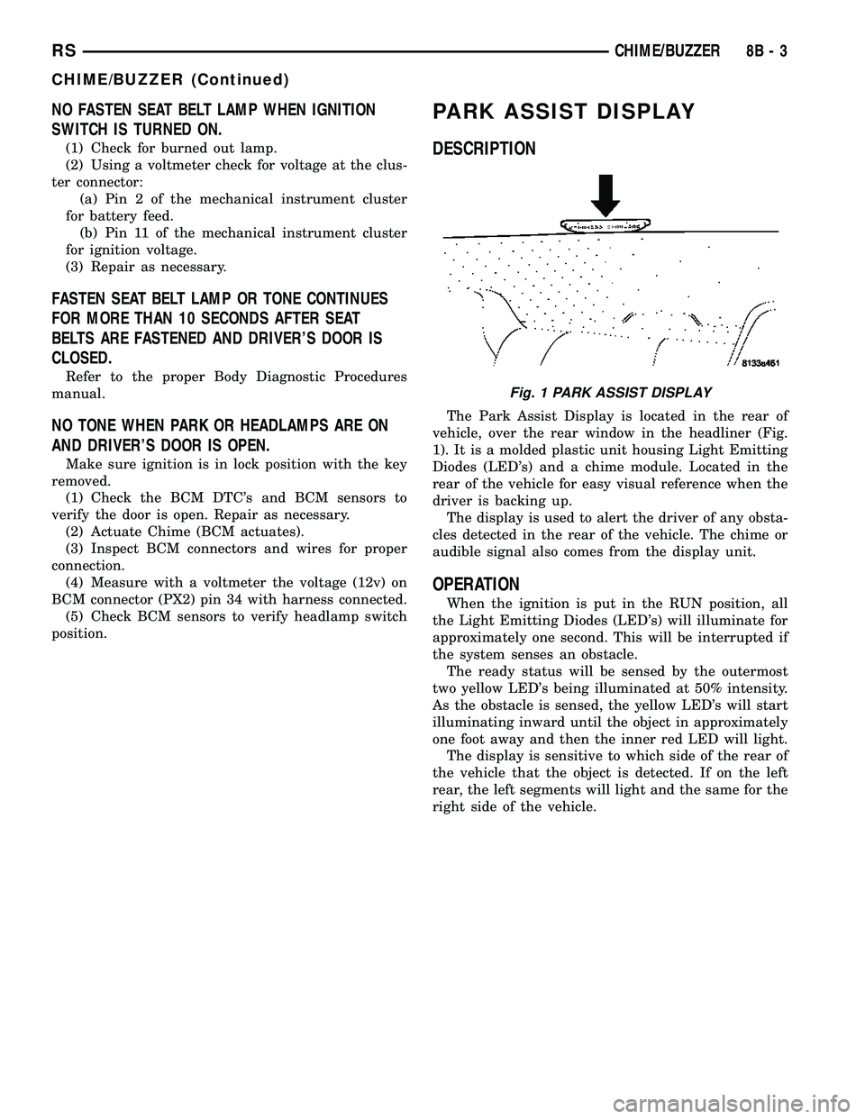
The Park Assist Display is located in the rear of
vehicle, over the rear window in the headliner (Fig.
1). It is a molded plastic unit housing Light Emitting
Diodes (LED's) and a chime module. Located in the
rear of the vehicle for easy visual reference when the
driver is backing up.
The display is used to alert the driver of any obsta-
cles detected in the rear of the vehicle. The chime or
audible signal also comes from the display unit.
OPERATION
When the ignition is put in the RUN position, all
the Light Emitting Diodes (LED's) will illuminate for
approximately one second. This will be interrupted if
the system senses an obstacle.
The ready status will be sensed by the outermost
two yellow LED's being illuminated at 50% intensity.
As the obstacle is sensed, the yellow LED's will start
illuminating inward until the object in approximately
one foot away and then the inner red LED will light.
The display is sensitive to which side of the rear of
the vehicle that the object is detected. If on the left
rear, the left segments will light and the same for the
right side of the vehicle.
Fig. 1 PARK ASSIST DISPLAY
RSCHIME/BUZZER8B-3
CHIME/BUZZER (Continued)
Page 290 of 2339
trical connector on the vehicle wiring harness. The
power source for the CAB is through the ignition
switch in the RUN or ON position. The CAB is on
the PCI bus.
OPERATION
The primary functions of the controller antilock
brake (CAB) are to:
²Monitor the antilock brake system for proper
operation.
²Detect wheel locking or wheel slipping tenden-
cies by monitoring the speed of all four wheels of the
vehicle.
²Control fluid modulation to the wheel brakes
while the system is in an ABS mode.
²Store diagnostic information.
²Provide communication to the DRBIIItscan tool
while in diagnostic mode.
²Illuminate the amber ABS warning indicator
lamp.
²(With traction control only) Illuminate the TRAC
ON lamp in the message center on the instrument
panel when a traction control event occurs.
²(with traction control only) Illuminate the TRAC
OFF lamp when the amber ABS warning indicator
lamp illuminates.
The CAB constantly monitors the antilock brake
system for proper operation. If the CAB detects a
fault, it will turn on the amber ABS warning indica-
tor lamp and disable the antilock braking system.
The normal base braking system will remain opera-
tional.
NOTE: If the vehicle is equipped with traction con-
trol, the TRAC OFF lamp will illuminate anytime the
amber ABS warning indicator lamp illuminates.The CAB continuously monitors the speed of each
wheel through the signals generated by the wheel
speed sensors to determine if any wheel is beginning
to lock. When a wheel locking tendency is detected,
the CAB commands the CAB command coils to actu-
ate. The coils then open and close the valves in the
HCU that modulate brake fluid pressure in some or
all of the hydraulic circuits. The CAB continues to
control pressure in individual hydraulic circuits until
a locking tendency is no longer present.
The CAB contains a self-diagnostic program that
monitors the antilock brake system for system faults.
When a fault is detected, the amber ABS warning
indicator lamp is turned on and the fault diagnostic
trouble code (DTC) is then stored in a diagnostic pro-
gram memory. A latched fault will disable certain
system functionality for the current ignition cycle. An
unlatched fault will disable certain system function-
ality until the fault condition disappears. These
DTC's will remain in the CAB memory even after the
ignition has been turned off. The DTC's can be read
and cleared from the CAB memory by a technician
using the DRBIIItscan tool. If not cleared with a
DRBIIItscan tool, the fault occurrence and DTC will
be automatically cleared from the CAB memory after
the identical fault has not been seen during the next
3,500 miles. Drive-off may be required for the amber
ABS warning indicator lamp to go out on the next
ignition cycle.
CAB INPUTS
²Wheel speed sensors (four)
²Brake lamp switch
²Ignition switch
²System and pump voltage
²Ground
²Traction control switch (if equipped)
²Diagnostic communication (PCI)
CAB OUTPUTS
²Amber ABS warning indicator lamp actuation
(via BUS)
²Red BRAKE warning indicator lamp actuation
(via BUS)
²Instrument cluster (MIC) communication (PCI)
²Traction control lamps (if equipped)
²Diagnostic communication (PCI, via BUS)
REMOVAL
(1) Disconnect the battery cables.
(2) Remove the battery (Refer to 8 - ELECTRI-
CAL/BATTERY SYSTEM/BATTERY - REMOVAL).
(3) Disconnect the vacuum hose connector at the
tank built into the battery tray.
(4) Remove the screw securing the coolant filler
neck to the battery tray.
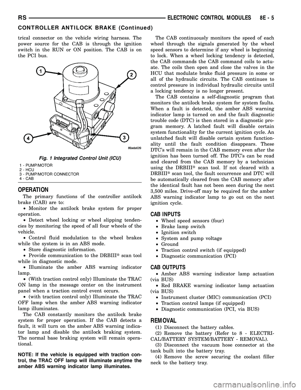
Fig. 1 Integrated Control Unit (ICU)
1 - PUMP/MOTOR
2 - HCU
3 - PUMP/MOTOR CONNECTOR
4 - CAB
RSELECTRONIC CONTROL MODULES8E-5
CONTROLLER ANTILOCK BRAKE (Continued)
Page 297 of 2339
²SCI Receive
²Speed Control
²Throttle Position Sensor
²Transmission Control Relay (Switched B+)
²Transmission Pressure Switches
²Transmission Temperature Sensor
²Transmission Input Shaft Speed Sensor
²Transmission Output Shaft Speed Sensor
²Transaxle Gear Engagement
²Vehicle Speed
NOTE: PCM Outputs:
²Air Conditioning Clutch Relay
²Automatic Shut Down (ASD) and Fuel Pump
Relays
²Data Link Connector (PCI and SCI Transmit)
²Double Start Override
²EGR Solenoid
²Fuel Injectors
²Generator Field
²High Speed Fan Relay
²Idle Air Control Motor
²Ignition Coils
²Leak Detection Pump
²Low Speed Fan Relay
²MTV Actuator
²Proportional Purge Solenoid
²SRV Valve
²Speed Control Relay
²Speed Control Vent Relay
²Speed Control Vacuum Relay
²8 Volt Output
²5 Volt Output
²Torque Reduction Request
²Transmission Control Relay
²Transmission Solenoids
²Vehicle Speed
Based on inputs it receives, the powertrain control
module (PCM) adjusts fuel injector pulse width, idle
speed, ignition timing, and canister purge operation.
The PCM regulates the cooling fans, air conditioning
and speed control systems. The PCM changes gener-
ator charge rate by adjusting the generator field.
The PCM adjusts injector pulse width (air-fuel
ratio) based on the following inputs.
²Battery Voltage
²Intake Air Temperature Sensor
²Engine Coolant Temperature
²Engine Speed (crankshaft position sensor)
²Exhaust Gas Oxygen Content (heated oxygen
sensors)
²Manifold Absolute Pressure
²Throttle Position
The PCM adjusts engine idle speed through the
idle air control motor based on the following inputs.
²Brake Switch²Engine Coolant Temperature
²Engine Speed (crankshaft position sensor)
²Park/Neutral
²Transaxle Gear Engagement
²Throttle Position
²Vehicle Speed
The PCM adjusts ignition timing based on the fol-
lowing inputs.
²Intake Air Temperature
²Engine Coolant Temperature
²Engine Speed (crankshaft position sensor)
²Knock Sensor
²Manifold Absolute Pressure
²Park/Neutral
²Transaxle Gear Engagement
²Throttle Position
The automatic shut down (ASD) and fuel pump
relays are mounted externally, but turned on and off
by the powertrain control module through the same
circuit.
The camshaft and crankshaft signals are sent to
the powertrain control module. If the PCM does not
receive both signals within approximately one second
of engine cranking, it deactivates the ASD and fuel
pump relays. When these relays are deactivated,
power is shut off to the fuel injectors, ignition coils,
fuel pump and the heating element in each oxygen
sensor.
The PCM contains a voltage converter that
changes battery voltage to a regulated 8.0 volts. The
8.0 volts power the camshaft position sensor, crank-
shaft position sensor and vehicle speed sensor. The
PCM also provides a 5.0 volts supply for the engine
coolant temperature sensor, intake air temperature
sensor, manifold absolute pressure sensor and throt-
tle position sensor.
The PCM engine control strategy prevents reduced
idle speeds until after the engine operates for 320 km
(200 miles). If the PCM is replaced after 320 km (200
miles) of usage, update the mileage in new PCM. Use
the DRBIIItscan tool to change the mileage in the
PCM. Refer to the appropriate Powertrain Diagnostic
Manual and the DRBIIItscan tool.
TRANSMISSION CONTROL
CLUTCH VOLUME INDEX (CVI)
An important function of the PCM is to monitor
Clutch Volume Index (CVI). CVIs represent the vol-
ume of fluid needed to compress a clutch pack.
The PCM monitors gear ratio changes by monitor-
ing the Input and Output Speed Sensors. The Input,
or Turbine Speed Sensor sends an electrical signal to
the PCM that represents input shaft rpm. The Out-
put Speed Sensor provides the PCM with output
shaft speed information.
8E - 12 ELECTRONIC CONTROL MODULESRS
POWERTRAIN CONTROL MODULE (Continued)
Page 300 of 2339
The power grounds are used to control the ground
side relays, solenoids, ignition coil or injectors. The
signal ground is used for any input that uses sensor
return for ground, and the ground side of any inter-
nal processing component.
The PCM case is shielded to prevent RFI and EMI.
The PCM case is grounded and must be firmly
attached to a good, clean body ground.
Internally all grounds are connected together, how-
ever there is noise suppression on the sensor ground.
For EMI and RFI protection the housing and cover
are also grounded separately from the ground pins.
OPERATION - 5 VOLT SUPPLY - PCM OUTPUT
The PCM supplies 5 volts to the following sensors:
²A/C pressure transducer
²Ambient Temperature sensor
²Battery temperature
²Camshaft Position Sensor (NGC)
²Crankshaft Position Sensor (NGC)
²Engine coolant temperature sensor
²Inlet Air Temperature Sensor
²Knock sensor
²Linear EGR solenoid (if equipped)
²Manifold absolute pressure sensor
²Oil Pressure Switch
²Throttle position sensor
STANDARD PROCEDURE
STANDARD PROCEDURE - OBTAINING
DIAGNOSTIC TROUBLE CODES
BULB CHECK
Key on: Bulb illuminated until vehicle starts, as
long as all once per trip (readiness) monitors com-
pleted. If monitors havenotbeen completed, then:
Key on: bulb check for about 5 to 8 seconds, lamp
then flashes if once per trip (readiness) monitors
havenotbeen completed until vehicle is started,
then MIL is extinguished.
OBTAINING DTC'S USING DRB SCAN TOOL
(1) Connect the DRB scan tool to the data link
(diagnostic) connector. This connector is located in
the passenger compartment; at the lower edge of
instrument panel; near the steering column.
(2) Turn the ignition switch on and access the
ªRead Faultº screen.
(3) Record all the DTC's and ªfreeze frameº infor-
mation shown on the DRB scan tool.
(4) To erase DTC's, use the ªErase Trouble Codeº
data screen on the DRB scan tool.Do not erase any
DTC's until problems have been investigated
and repairs have been performed.
STANDARD PROCEDURE - PINION FACTOR
SETTING
NOTE: This procedure must be performed if the
PCM has been replaced with a NEW or replacement
unit. Failure to perform this procedure will result in
an inoperative or improperly calibrated speedome-
ter.
The vehicle speed readings for the speedometer are
taken from the output speed sensor. The PCM must
be calibrated to the different combinations of equip-
ment (final drive and tires) available. Pinion Factor
allows the technician to set the Powertrain Control
Module initial setting so that the speedometer read-
ings will be correct. To properly read and/or reset the
Pinion Factor, it is necessary to use a DRBIIItscan
tool.
(1) Plug the DRBIIItscan tool into the diagnostic
connector located under the instrument panel.
(2) Select the Transmission menu.
(3) Select the Miscellaneous menu.
(4) Select Pinion Factor. Then follow the instruc-
tions on the DRBIIItscan tool screen.
STANDARD PROCEDURE - QUICK LEARN
PROCEDURE
The quick learn procedure requires the use of the
DRBIIItscan tool. This program allows the PCM to
recalibrate itself. This will provide the best possible
transaxle operation.
NOTE: The quick learn procedure should be per-
formed if any of the following procedures are per-
formed:
²Transaxle Assembly Replacement
²Powertrain Control Module Replacement
²Solenoid/Pressure Switch Assembly Replacement
²Clutch Plate and/or Seal Replacement
²Valve Body Replacement or Recondition
To perform the Quick Learn Procedure, the follow-
ing conditions must be met:
²The brakes must be applied
²The engine speed must be above 500 rpm
²The throttle angle (TPS) must be less than 3
degrees
²The shift lever position must stay until
prompted to shift to overdrive
²The shift lever position must stay in overdrive
after the Shift to Overdrive prompt until the
DRBIIItindicates the procedure is complete
²The calculated oil temperature must be above
60É and below 200É
RSELECTRONIC CONTROL MODULES8E-15
POWERTRAIN CONTROL MODULE (Continued)
Page 353 of 2339
Hard wired circuitry connects the heated seat sys-
tem components to each other through the electrical
system of the vehicle. These circuits may be con-
nected to each other, to the vehicle electrical system
and to the heated seat system components through
the use of a combination of soldered splices and
splice block connectors. Refer to the appropriate wir-
ing information for complete circuit schematic or con-
nector pin-out information.
OPERATION
The heated seat system components operate on
battery current received through a fuse in the Inte-
grated Power Module (IPM) on a fused ignition
switch output (run) circuit from the Body Control
Module (BCM). The system will only operate when
the ignition switch is in the On position. The heated
seat system will be turned Off automatically when-
ever the ignition switch is turned to any position
except On. Also, the heated seat system will not oper-
ate when the surface temperature of the seat cushion
cover at either heated seat sensor is above the
designed temperature set points of the system.
DIAGNOSIS AND TESTING
HEATED SEAT SYSTEM
The most efficient means of diagnosing the heated
seat system is by individual component. For diagno-
sis of a specific component refer to the following:
²Heated seat module, (Refer to 8 - ELECTRICAL/
ELECTRONIC CONTROL MODULES/MEMORY
HEATED SEAT/MIRROR MODULE - DIAGNOSIS
AND TESTING).
²Heated seat elements, (Refer to 8 - ELECTRI-
CAL/HEATED SEATS/HEATED SEAT ELEMENT -
DIAGNOSIS AND TESTING).
²Heated seat switch, (Refer to 8 - ELECTRICAL/
HEATED SEATS/DRIVER HEATED SEAT SWITCH
- DIAGNOSIS AND TESTING).
²Heated seat sensor, (Refer to 8 - ELECTRICAL/
HEATED SEATS/HEATED SEAT SENSOR - DIAG-
NOSIS AND TESTING).
Refer to the appropriate wiring information for
complete circuit schematic or connector pin-out infor-
mation.
HEATED SEAT SWITCH
DESCRIPTION
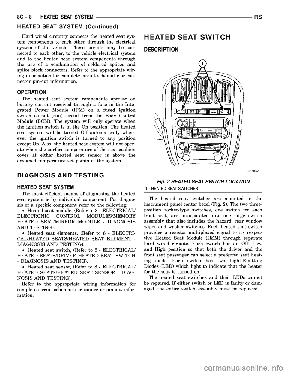
The heated seat switches are mounted in the
instrument panel center bezel (Fig. 2). The two three-
position rocker-type switches, one switch for each
front seat, are incorporated into one large switch
assembly that also includes the hazard, rear window
wiper and washer switches. Each heated seat switch
provides a resistor multiplexed signal to its respec-
tive Heated Seat Module (HSM) through separate
hard wired circuits. Each switch has an Off, Low,
and High position so that both the driver and the
front seat passenger can select a preferred seat heat-
ing mode. Each switch has two Light-Emitting
Diodes (LED) which light to indicate that the heater
for the seat is turned on.
The heated seat switches and their LEDs cannot
be repaired. If either switch or LED is faulty or dam-
aged, the entire switch assembly must be replaced.
Fig. 2 HEATED SEAT SWITCH LOCATION
1 - HEATED SEAT SWITCHES
8G - 8 HEATED SEAT SYSTEMRS
HEATED SEAT SYSTEM (Continued)
Page 354 of 2339
OPERATION
There are three positions that can be selected with
each of the heated seat switches: Off, Low, or High.
When the left side of the switch rocker is fully
depressed, the Low position is selected and the low
position LED indicator illuminates. When the right
side of the switch rocker is fully depressed, the High
position is selected and the high position LED indi-
cator illuminates. When the switch rocker is moved
to its neutral position (middle), Off is selected and
both LED indicators are extinguished.
Each switch provides separate resistor, hard wire
inputs to its respective Heated Seat Module (HSM) to
indicate the selected switch position. The heated seat
module responds to the heated seat switch status
messages by controlling the output to the seat heater
elements of the selected seat. The Low heat position
set point is about 36É C (97É F), and the High heat
position set point is about 41É C (105É F).
DIAGNOSIS AND TESTING
DRIVER HEATED SEAT SWITCH
Refer to the appropriate wiring information for
complete circuit schematic or connector pin-out infor-
mation.
WARNING: REFER TO THE RESTRAINTS SECTION
OF THIS MANUAL BEFORE ATTEMPTING ANY
STEERING WHEEL, STEERING COLUMN, SEAT OR
INSTRUMENT PANEL COMPONENT DIAGNOSIS OR
SERVICE. FAILURE TO TAKE THE PROPER PRE-
CAUTIONS COULD RESULT IN ACCIDENTAL AIR-
BAG DEPLOYMENT AND POSSIBLE PERSONAL
INJURY.
CHECKING SWITCH SIGNAL AND WIRING AT THE
MODULE
(1) Disconnect and isolate the battery negative
cable.
(2) Access and disconnect the gray 4-way connector
from the heated seat module. Visually inspect wiring
terminals for damage that would prevent positive
connection. If not OK, repair or replace the necessary
components.(3) Connect the battery negative cable. Place the
heated seat switch in the LO position. Using an
Ohmmeter, check the resistance between cavities 2
and 3 of the gray connector noted above. Resistance
should be about 3.5 kilohms (3500 ohms). If not OK,
check resistance directly at switch, as noted below. If
OK, proceed to the next step. If not OK, replace the
faulty switch.
(4) Place the heated seat switch in the HI position.
Using an ohmmeter, check the resistance between
cavities 2 and 3 of the gray connector noted above.
Resistance should be about 1.4 kilohms (1400 ohms).
If not OK, check resistance directly at the switch, as
indicated in the Heated Seat Switch Test Table. If
OK, proceed. If not OK replace the faulty switch.
(5) With the system ON in the HI position, check
for battery voltage and ground at cavities 4 and 1. If
OK, proceed with testing remaining components. If
not OK, repair open or shorted wiring.
CHECKING SWITCH ONLY
(1) Disconnect and isolate the battery negative
cable. Remove the center bezel from the instrument
panel (Refer to 23 - BODY/INSTRUMENT PANEL/
INSTRUMENT PANEL CENTER BEZEL -
REMOVAL). Check for continuity between the
ground circuit cavity (#10) of the instrument panel
center bezel switch electrical connector and a good
ground. There should be continuity. If OK, go to Step
2. If not OK, repair the open ground circuit to ground
as required.
(2) Connect the battery negative cable. Turn the
ignition switch to the On position. Check for battery
voltage at the fused ignition switch output (run) cir-
cuit cavity of the instrument panel center bezel
switch electrical connector (#4). If OK, turn the igni-
tion switch to the Off position, and go to Step 3. If
not OK, repair the open fused ignition switch output
(run) circuit as required.
(3) Test the heated seat switch as shown in the
Heated Seat Switch Test chart and the connector pin-
out below (Fig. 3). If OK, go to Step 4. If not OK,
replace the instrument panel center bezel switch
assembly.
RSHEATED SEAT SYSTEM8G-9
HEATED SEAT SWITCH (Continued)
Page 356 of 2339
(3) Install the center bezel onto the instrument
panel, (Refer to 23 - BODY/INSTRUMENT PANEL/
INSTRUMENT PANEL CENTER BEZEL - INSTAL-
LATION).
(4) Connect the battery negative cable.
HEATED SEAT ELEMENTS
DESCRIPTION
The heated seat system includes two seat heating
elements in each front seat, one for the seat cushion
and the other for the seat back. The two elements for
each seat that are connected in series with the
Heated Seat Module (HSM). The temperature sensor
is a Negative Temperature Coefficient (NTC) ther-
mistor. One temperature sensor is used for each seat,
and it is located on the seat cushion heating element
for all models.
The seat heating elements are attached to the seat
cushion cover trim and seat back cover trim units.
The heated seat elements and the temperature sen-
sor cannot be adjusted or repaired and, if faulty or
damaged, the seat element assembly must be
replaced, (Refer to 8 - ELECTRICAL/HEATED
SEATS/HEATED SEAT ELEMENT - REMOVAL).
OPERATION
The heated seat elements resist the flow of electri-
cal current. When battery current is passed through
the elements, the resistance of the elements to the
current flow is released in the form of heat. The tem-
perature sensor is a Negative Temperature Coeffi-
cient (NTC) thermistor. When the temperature of the
seat cushion cover rises, the resistance of the sensor
decreases. The heated seat module supplies a five-
volt signal to one side of each sensor, and monitors
the voltage drop through the sensor on a return cir-
cuit. The heated seat module uses this temperature
sensor input to monitor the temperature of the seat,
and regulates the current flow to the seat heating
elements accordingly.
DIAGNOSIS AND TESTING
HEATED SEAT ELEMENTS
The wire harness connectors for the seat cushion
and seat back heating elements are located under the
seat, at the heated seat module. Refer to the appro-
priate wiring information for complete circuit sche-
matic or connector pin-out information.
In order to access and test the heated seat ele-
ments it will be necessary to remove the appropriate
front seat retaining bolts and lay the seat rearward,
up against one of the rear seats. It is not necessary
to disconnect the seat electrical connectors, just use
care not to damage the attached wire harnesses
while testing.
NOTE: When checking heated seat elements for
continuity, be certain to move the heating element
being checked. Moving the element, such as sitting
in the seat will eliminate the possibility of an inter-
mittent open in the element which would only be
evident if the element was in a certain position.
Failure to check the element in various positions
could result in an incomplete test.
SEAT CUSHION ELEMENT
(1) From under the vehicle, remove the appropri-
ate seats four retaining nuts.
(2) From inside the vehicle, pull the seat up, off
the mounting studs and lay it back, up against one of
the rear seats.
(3) Locate the heated seat module, attached to the
bottom of the seat cushion pan. Remove the heated
seat module from the seat cushion pan. Do not dis-
connect the electrical connectors at this time.
(4) Locate and disconnect the green 4-way electri-
cal connector, connected to the heated seat module.
(5) Check for continuity between the two outboard
circuit cavities of the wire harness connector (Pins
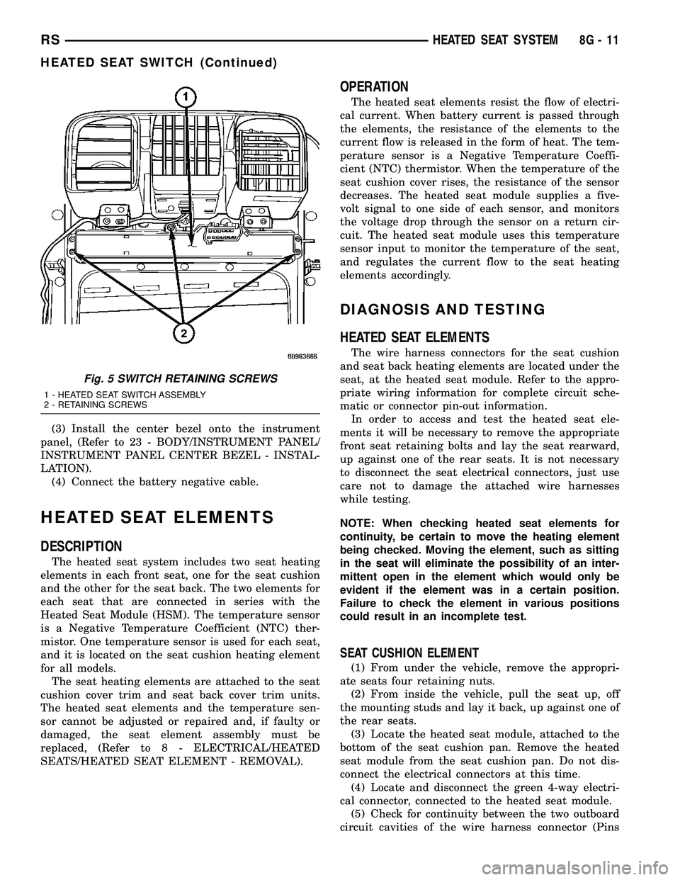
Fig. 5 SWITCH RETAINING SCREWS
1 - HEATED SEAT SWITCH ASSEMBLY
2 - RETAINING SCREWS
RSHEATED SEAT SYSTEM8G-11
HEATED SEAT SWITCH (Continued)
Page 366 of 2339
FIRING ORDERAUTO SHUT DOWN RELAY
DESCRIPTION
The relay is located in the Power Distribution Cen-
ter (PDC). For the location of the relay within the
PDC, refer to the PDC cover for location. Check elec-
trical terminals for corrosion and repair as necessary
OPERATION
The engine switched battery (NGC vehicles)
informs the PCM when the ASD relay energizes. A 12
volt signal at this input indicates to the PCM that
the ASD has been activated. This input is also used
to power certain drivers on NGC vehicles.
When energized, the ASD relay on NGC vehicles
provides power to operate the injectors, ignition coil,
generator field, O2 sensor heaters (both upstream
and downstream), evaporative purge solenoid, EGR
solenoid (if equipped) wastegate solenoid (if
equipped), and NVLD solenoid (if equipped).
The ASD relay also provides a sense circuit to the
PCM for diagnostic purposes. If the PCM does not
receive 12 volts from this input after grounding the
control side of the ASD relay, it sets a Diagnostic
Trouble Code (DTC). The PCM energizes the ASD
any time there is an engine speed that exceeds a pre-
determined value (typically about 50 rpm). The ASD
relay can also be energized after the engine has been
turned off to perform an O2 sensor heater test, if
vehicle is equipped with OBD II diagnostics.
As mentioned earlier, the PCM energizes the ASD
relay during an O2 sensor heater test. On NGC vehi-
cles it checks the O2 heater upon vehicle start. The
PCM still operates internally to perform several
checks, including monitoring the O2 sensor heaters.
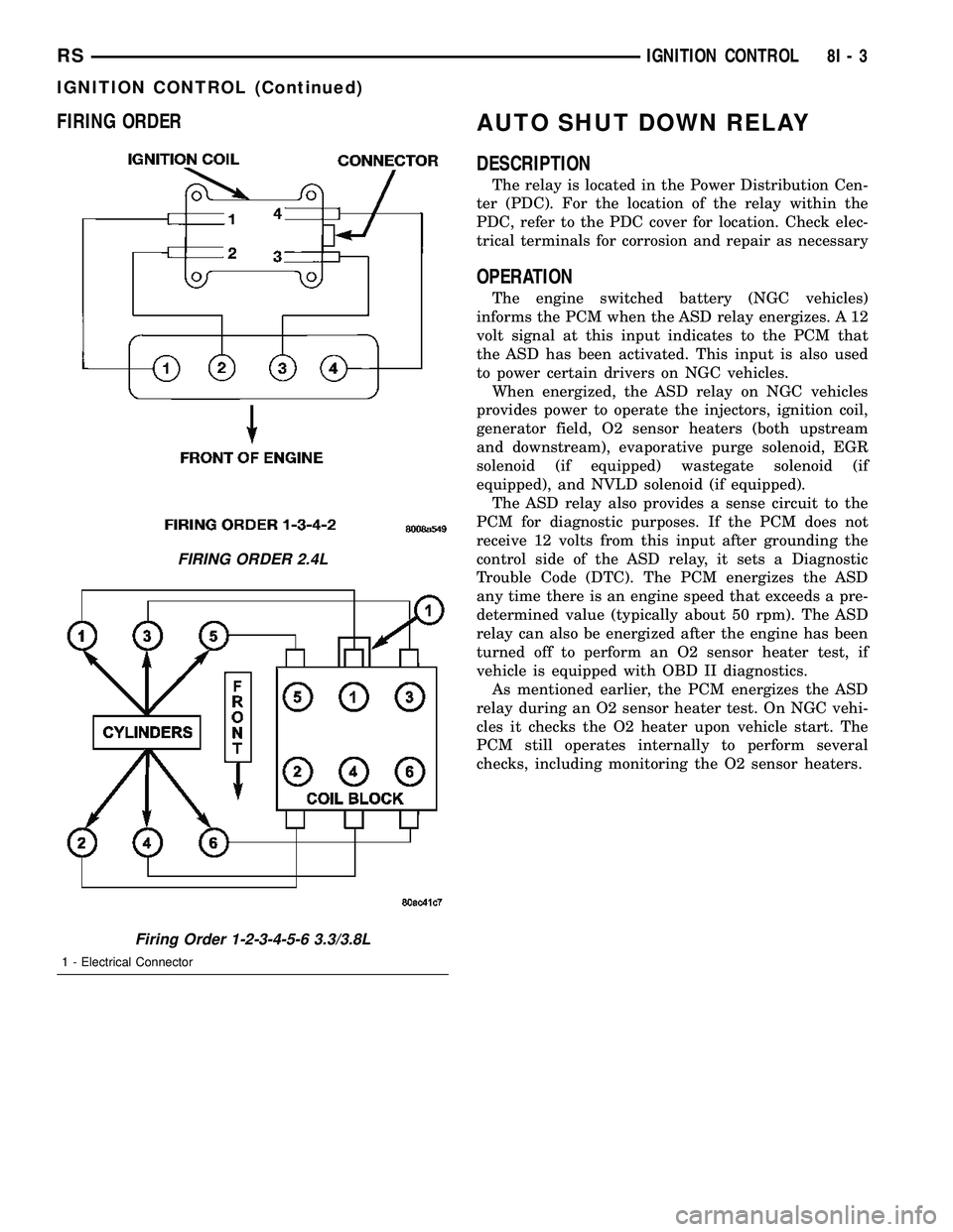
FIRING ORDER 2.4L
Firing Order 1-2-3-4-5-6 3.3/3.8L
1 - Electrical Connector
RSIGNITION CONTROL8I-3
IGNITION CONTROL (Continued)