turn signal CHRYSLER CARAVAN 2005 Owner's Manual
[x] Cancel search | Manufacturer: CHRYSLER, Model Year: 2005, Model line: CARAVAN, Model: CHRYSLER CARAVAN 2005Pages: 2339, PDF Size: 59.69 MB
Page 420 of 2339
NOTE: If a new CMTC module has been installed,
the compass will have to be calibrated and the vari-
ance set. (Refer to 8 - ELECTRICAL/OVERHEAD
CONSOLE - STANDARD PROCEDURE - COMPASS
CALIBRATION).
UNIVERSAL TRANSMITTER
DESCRIPTION
A Universal Transmitter transceiver is available on
some vehicles. The universal transmitter transceiver
is integral to the Electronic Vehicle Information Cen-
ter (EVIC) and the Compass Mini-Trip Computer
(CMTC) modules, which are located in the overhead
console. The only visible component of the universal
transmitter are the three transmitter push buttons
centered between the modules push buttons located
just rearward of the display screen in the overhead
console. The three universal transmitter push but-
tons are identified with one, two or three light indi-
cators so that they can be easily identified.
Each of the three universal transmitter push but-
tons controls an independent radio transmitter chan-
nel. Each of these three channels can be trained to
transmit a different radio frequency signal for the
remote operation of garage door openers, motorized
gate openers, home or office lighting, security sys-
tems or just about any other device that can be
equipped with a radio receiver in the 286 to 399
MegaHertz (MHz) frequency range for remote opera-
tion. The universal transmitter is capable of operat-
ing systems using either rolling code or non-rolling
code technology.
The electronics module displays messages and a
small house-shaped icon with one, two or three dots
corresponding to the three transmitter buttons to
indicate the status of the universal transmitter. The
EVIC messages are:
²Cleared Channels- Indicates that all of the
transmitter codes stored in the universal transmitter
have been successfully cleared.
²Training- Indicates that the universal trans-
mitter is in its transmitter learning mode.
²Trained- Indicates that the universal transmit-
ter has successfully acquired a new transmitter code.
²Transmit- Indicates that a trained universal
transmitter button has been depressed and that the
universal transmitter is transmitting.
The universal transmitter cannot be repaired, and
is available for service only as a unit with the EVIC
or CMTC modules. If any of these components is
faulty or damaged, the complete EVIC or CMTC
module must be replaced.
DIAGNOSIS AND TESTING
UNIVERSAL TRANSMITTER
If both the Universal Transmitter and the Elec-
tronic Vehicle Information Center (EVIC) are inoper-
ative, (Refer to 8 - ELECTRICAL/OVERHEAD
CONSOLE/ELECTRONIC VEHICLE INFO CENTER
- DIAGNOSIS AND TESTING). If the Universal
Transmitter is inoperative, but the EVIC is operating
normally, retrain the Transmitter with a known good
transmitter (Refer to 8 - ELECTRICAL/OVERHEAD
CONSOLE/UNIVERSAL TRANSMITTER - STAN-
DARD PROCEDURE - SETTING TRANSMITTER
CODES). If the unit is still inoperative, test the uni-
versal transmitter with the Radio Frequency Detec-
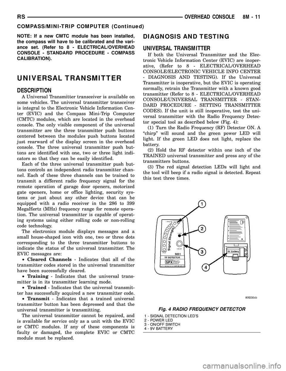
tor special tool as described below (Fig. 4):
(1) Turn the Radio Frequency (RF) Detector ON. A
ªchirpº will sound and the green power LED will
light. If the green LED does not light, replace the
battery.
(2) Hold the RF detector within one inch of the
TRAINED universal transmitter and press any of the
transmitters buttons.
(3) The red signal detection LEDs will light and
the tool will beep if a radio signal is detected. Repeat
this test three times.
Fig. 4 RADIO FREQUENCY DETECTOR
1 - SIGNAL DETECTION LED'S
2 - POWER LED
3 - ON/OFF SWITCH
4 - 9V BATTERY
RSOVERHEAD CONSOLE8M-11
COMPASS/MINI-TRIP COMPUTER (Continued)
Page 421 of 2339
STANDARD PROCEDURE
SETTING TRANSMITTER CODES
(1) Turn off the engine.
(2) Erase the codes by pressing the two outside
buttons. Release the buttons when the display con-
firms the operation (about 20 seconds).
(3) Choose one of the three buttons to train. Place
the hand-held transmitter within one inch of the uni-
versal transmitter and push the buttons on both
transmitters.
(4) Release both buttons. Your universal transmit-
ter is now ªtrainedº. To train the other buttons,
repeat Step 3 and Step 4. Be sure to keep your hand-
held transmitter in case you need to retrain the uni-
versal transmitter.
ERASING TRANSMITTER CODES
To erase the universal transmitter codes, simply
hold down the two outside buttons until the display
confirms the operation.
NOTE: Individual channels cannot be erased. Eras-
ing the transmitter codes will erase ALL pro-
grammed codes.
REMOVAL
(1) For the universal transmitter removal proce-
dure, (Refer to 8 - ELECTRICAL/OVERHEAD CON-
SOLE/COMPASS/MINI-TRIP COMPUTER -
REMOVAL.
AMBIENT TEMP SENSOR
DESCRIPTION
Ambient air temperature is monitored by the over-
head console through ambient temperature messages
received from the Powertrain Control Module (PCM)
over the Programmable Communications Interface
(PCI) data bus circuit. The PCM receives a hard
wired input from the ambient temperature sensor.
The ambient temperature sensor is a variable resis-
tor mounted to a bracket that is secured with a screw
to the right side of the headlamp mounting module
grille opening, behind the radiator grille and in front
of the engine compartment.
For additional information on the PCM, (Refer to 8
- ELECTRICAL/ELECTRONIC CONTROL MOD-
ULES/POWERTRAIN CONTROL MODULE -
DESCRIPTION).
OPERATION
The ambient temperature sensor is a variable
resistor that operates on a five-volt reference signal
sent by the Powertrain Control Module (PCM). The
resistance in the sensor changes as temperature
changes, changing the temperature sensor signal cir-
cuit voltage to the PCM. Based upon the resistance
in the sensor, the PCM senses a specific voltage on
the temperature sensor signal circuit, which it is pro-
grammed to correspond to a specific temperature.
The PCM then sends the proper ambient tempera-
ture messages to the Electronic Vehicle Information
Center (EVIC)/Compass Mini-Trip Computer (CMTC)
over the Programmable Communication Interface
(PCI) data bus.
The thermometer function is supported by the
ambient temperature sensor, a wiring circuit, the
PCM, the PCI data bus, and the Electronics module.
If any portion of the ambient temperature sensor cir-
cuit fails, the PCM will self-diagnose the circuit.
The ambient temperature sensor circuit can also be
diagnosed manually (Refer to 8 - ELECTRICAL/
OVERHEAD CONSOLE/AMBIENT TEMP SENSOR
- DIAGNOSIS AND TESTING - AMBIENT TEM-
PERATURE SENSOR CIRCUIT). If the temperature
sensor and circuit are confirmed to be OK, but the
temperature display is inoperative or incorrect,
(Refer to 8 - ELECTRICAL/OVERHEAD CONSOLE -
DIAGNOSIS AND TESTING) to determine the cause.
For complete circuit diagrams, refer to the appropri-
ate wiring information.
DIAGNOSIS AND TESTING
AMBIENT TEMPERATURE SENSOR
(1) Turn the ignition switch to the Off position.
Disconnect and isolate the battery negative cable.
Disconnect the ambient temperature sensor wire har-
ness connector.
(2) Measure the resistance of the ambient temper-
ature sensor. At room temperature (approx. 68ÉF),
the sensor resistance should be between 10-13 Kilo-
hms. The sensor resistance should be between these
two values at 68ÉF. If the resistance is out of range
replace the ambient temperature sensor.
AMBIENT TEMPERATURE SENSOR CIRCUIT
(1) Turn the ignition switch to the Off position.
Disconnect and isolate the battery negative cable.
Disconnect the ambient temperature sensor wire har-
ness connector and the Powertrain Control Module
(PCM) wire harness connector.
8M - 12 OVERHEAD CONSOLERS
UNIVERSAL TRANSMITTER (Continued)
Page 422 of 2339
(2) Connect a jumper wire between the two termi-
nals in the body half of the ambient temperature sen-
sor wire harness connector.
(3) Check for continuity between the sensor return
circuit and the ambient temperature sensor signal
circuit cavities of the PCM wire harness connector.
There should be continuity. If OK, go to Step 4. If not
OK, repair the open sensor return circuit or ambient
temperature sensor signal circuit to the ambient tem-
perature sensor as required.
(4) Remove the jumper wire from the body half of
the ambient temperature sensor wire harness con-
nector. Check for continuity between the sensor
return circuit cavity of the PCM wire harness connec-
tor and a good ground. There should be no continuity.
If OK, go to Step 5. If not OK, repair the shorted
sensor return circuit as required.
(5) Check for continuity between the ambient tem-
perature sensor signal circuit cavity of the PCM wire
harness connector and a good ground. There should
be no continuity. If OK, (Refer to 8 - ELECTRICAL/
OVERHEAD CONSOLE - DIAGNOSIS AND TEST-ING) to determine the cause. If not OK, repair the
shorted ambient temperature sensor signal circuit as
required.
REMOVAL
(1) Disconnect and isolate the battery negative
cable.
(2) From behind the front bumper fascia, remove
the screw holding the sensor to the radiator closure
panel.
(3) Disconnect the sensor electrical connector.
(4) Remove the sensor from vehicle.
INSTALLATION
(1) Position the sensor in the vehicle and connect
the sensor electrical connector.
(2) From behind the front bumper fascia, install
the sensor mounting screw.
(3) Connect the battery negative cable.
RSOVERHEAD CONSOLE8M-13
AMBIENT TEMP SENSOR (Continued)
Page 432 of 2339
(2) Remove the rear light bar assembly from the
vehicle. (Refer to 8 - ELECTRICAL/POWER DOORS/
SWITCH - REMOVAL) for the procedure.
(3) Grasp the light bar at its sides next to ther-
mistor/chime assembly and gently pull the two sides
of the light bar apart until the thermistor/chime
assembly can be removed.
INSTALLATION
(1) Gently pull the two sides of the light bar apart
until the thermistor/chime assembly can be installed.
(2) Install the rear light bar assembly on the vehi-
cle. (Refer to 8 - ELECTRICAL/POWER DOORS/
SWITCH - INSTALLATION) for the procedure.
(3) Connect the battery negative cable.
ENGAGE ACTUATOR
DESCRIPTION
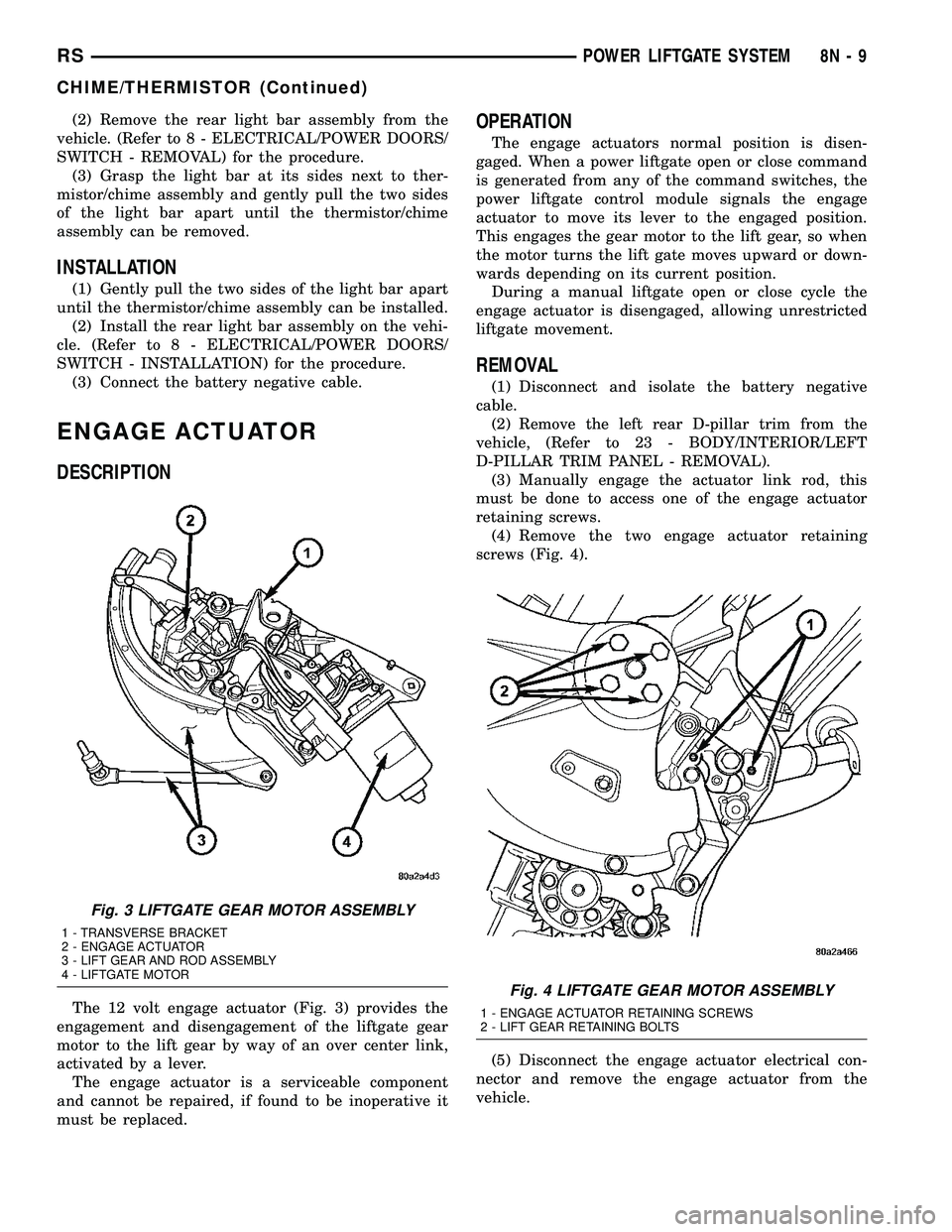
The 12 volt engage actuator (Fig. 3) provides the
engagement and disengagement of the liftgate gear
motor to the lift gear by way of an over center link,
activated by a lever.
The engage actuator is a serviceable component
and cannot be repaired, if found to be inoperative it
must be replaced.
OPERATION
The engage actuators normal position is disen-
gaged. When a power liftgate open or close command
is generated from any of the command switches, the
power liftgate control module signals the engage
actuator to move its lever to the engaged position.
This engages the gear motor to the lift gear, so when
the motor turns the lift gate moves upward or down-
wards depending on its current position.
During a manual liftgate open or close cycle the
engage actuator is disengaged, allowing unrestricted
liftgate movement.
REMOVAL
(1) Disconnect and isolate the battery negative
cable.
(2) Remove the left rear D-pillar trim from the
vehicle, (Refer to 23 - BODY/INTERIOR/LEFT
D-PILLAR TRIM PANEL - REMOVAL).
(3) Manually engage the actuator link rod, this
must be done to access one of the engage actuator
retaining screws.
(4) Remove the two engage actuator retaining
screws (Fig. 4).
(5) Disconnect the engage actuator electrical con-
nector and remove the engage actuator from the
vehicle.
Fig. 3 LIFTGATE GEAR MOTOR ASSEMBLY
1 - TRANSVERSE BRACKET
2 - ENGAGE ACTUATOR
3 - LIFT GEAR AND ROD ASSEMBLY
4 - LIFTGATE MOTOR
Fig. 4 LIFTGATE GEAR MOTOR ASSEMBLY
1 - ENGAGE ACTUATOR RETAINING SCREWS
2 - LIFT GEAR RETAINING BOLTS
RSPOWER LIFTGATE SYSTEM8N-9
CHIME/THERMISTOR (Continued)
Page 444 of 2339
a second time. Pressing the Panic button also acti-
vates the courtesy lamps. Pressing the Panic button
again stops the exterior lamps from flashing and the
horn from sounding. However, the courtesy lamps
will remain illuminated until either the BCM times
out lamp operation or until the turning of the igni-
tion. The panic feature will operate if the ignition is
ON, but only if the Panic button is pressed prior to
starting the vehicle. A vehicle speed of about 25.7
km/h (15 miles-per-hour) will also cancel the panic
event.
The RKE system can also perform other functions
on this vehicle. If the vehicle is equipped with the
optional Vehicle Theft Security System (VTSS), the
RKE transmitter will arm the VTSS when the Lock
button is depressed, and disarm the VTSS when the
Unlock button is depressed.
The RKE system includes two transmitters when
the vehicle is shipped from the factory, but the sys-
tem can retain the vehicle access codes of up to a
total of eight transmitters. If an RKE transmitter is
inoperative or lost, new transmitter vehicle access
codes can be programmed into the system using a
DRB IIItscan tool.
This vehicle also offers several customer program-
mable features, which allows the selection of several
optional electronic features to suit individual prefer-
ences. Customer programmable feature options
affecting the RKE system include:
²Automatic Door Lock- Customer programma-
ble feature that allows the BCM to perform an auto-
matic door lock if the vehicle speed is above 25.7
km/h (15 miles-per-hour).
²Automatic Door Unlock On Exit- Customer
programmable feature that allows the BCM to per-
form an automatic door unlock if the vehicle speed is
0, vehicle in park and driver door is opened.
²Flash Lights with Lock and Unlock- Allows
the option of having the park lamps flash as an opti-
cal verification that the RKE system received a valid
Lock request or Unlock request from the RKE trans-
mitter, or having no optical verification.
²Programming Additional Transmitters-
Allows up to a total of four transmitter vehicle access
codes to be stored.
²Remote Unlock Sequence- Allows the option
of having only the driver side front door unlock when
the RKE transmitter Unlock button is depressed the
first time. The remaining doors unlock when the but-
ton is depressed a second time within 5 seconds of
the first unlock press. Another option is having all
doors unlock upon the first depression of the RKE
transmitter Unlock button.
²Sound Horn on Lock- Allows the option of
having the horn sound a short chirp as an audible
verification that the RKE system received a validLock request from the RKE transmitter, or having no
audible verification.
OPERATION
POWER LOCKS
The Body Control Module (BCM) locks or unlocks
the doors when an actuation input signal from a door
lock switch, Central Lock key cylinder or Remote
Keyless Entry (RKE) is received. The BCM turns on
the output drivers and provides a voltage level to the
door lock motor for a specified time.
REMOTE KEYLESS ENTRY
The RKE transmitter uses radio frequency signals
to communicate with the SKREEM module. The
SKREEM is on the PCI bus. When the operator
presses a button on the transmitter, it sends a spe-
cific request to the SKREEM. In turn, the SKREEM
sends the appropriate request over the PCI bus to
the following:
²Integrated Power Module (IPM)- to activate
the park lamps, the headlamps and the horn for the
horn chirp.
²Power Liftgate Module (PLGM)- to control
the liftgate lock and unlock functions.
After pressing the lock button on the RKE trans-
mitter, all of the door locks will lock, the illuminated
entry will turn off (if all doors are closed) and the
vehicle theft security system (if equipped) will arm.
Pressing the unlock button one time will unlock
the driver door, or all doors based on the customer
programmable feature enabled, the illuminated entry
will turn on the courtesy lamps and the vehicle theft
security system (if equipped) will disarm. Pressing
the unlock button a second time, the remaining door
locks will unlock.
If the vehicle is equipped with the memory system,
the memory message will identify which transmitter
(1 or 2) sent the signal.
ROLLING CODE
The rolling code feature changes part of the trans-
mitter message each time that it is used. The trans-
mitter message and the receiver message increment
together. Under certain conditions with a rolling code
system, such as pressing a button on the RKE trans-
mitter over 255 times outside of receiver range or
replacing the battery, the receiver and transmitter
can fall out of synchronization. To re-synchronize,
press and release the UNLOCK button on the RKE
transmitter repeatedly (it may take up to eight
cycles) while listening carefully for the power door
locks in the vehicle to cycle, indicating that resyn-
chronization has occurred.
RSPOWER LOCKS8N-21
POWER LOCKS (Continued)
Page 445 of 2339

The lock function works from the RKE transmitter
even in an out of synchronization condition, therefore
it could be verified by pressing the LOCK button on
the RKE key fob.
DOOR CYLINDER LOCK
SWITCH - EXPORT
DESCRIPTION
The Door Cylinder Lock Switch (If equipped) is
used to:
²Unlock/Lock all the doors via the Central Lock-
ing feature.
²Arm/Disarm the Vehicle Theft Security System.
²Trigger the Illuminated Entry feature.
The door cylinder lock switch is mounted to the
rear of the driver door lock cylinder. When installed
on the rear of the cylinder, there is a tab on the lock
cylinder that aligns with the switch to prevent it
from turning. An anti-rotating device. The door cylin-
der lock switch is a one time use switch. Once it is
removed from the rear of the door lock cylinder, it
may not be reinstalled and a new switch must be
used.
OPERATION
When the Door Cylinder Lock Switch is turned
either way using the door key cylinder, the BCM
reads a direct message signal from the switch.
If turning the key cylinder once, toward the front
of the vehicle, this will:
(1) Mechanically unlock the door lock.
(2) Disarm the Vehicle Theft Security System (if
equipped).
(3) Turn on the Illuminated Entry (if equipped) for
approximately 30 seconds.
If the key cylinder is turned to the unlock position
(toward the front of vehicle) twice within two sec-
onds, all the doors and liftgate will unlock (if
equipped with the central locking feature).
To lock the vehicle using the door cylinder lock
switch, turn the key cylinder toward the rear of the
vehicle once. This will lock the door that you are
using the key on. If equipped with the central locking
feature, this will lock all the other doors and liftgate.
Furthermore, this will arm the vehicle theft security
system and turn off the illuminated entry.
DIAGNOSIS AND TESTING
DOOR CYLINDER LOCK SWITCH - EXPORT
Any diagnosis of the power lock system
should begin with the use of the DRB IIItdiag-
nostic tool. For information on the use of theDRB IIIt, refer to the appropriate Diagnostic
Service Manual.
For complete circuit diagrams, refer to the appro-
priate wiring information.
(1) Visually inspect the switch for proper installa-
tion. Make sure it is seated on the rear of the key
cylinder, with the tab of the door key cylinder prop-
erly aligned with the slot on the door cylinder lock
switch.
(2) Disconnect the switch at the harness connector
and check the resistance in each switch position.
CAUTION: Do not disconnect the switch from the
rear of the door key cylinder. This switch is a one
time use switch. Once it is removed from the rear of
the switch, it is not reusable and must be replaced.
Test the switch at the harness connector.
DOOR CYLINDER LOCK SWITCH RESISTANCE
SWITCH POSITION RESISTANCE VALUE
COUNTERCLOCKWISE 5.4K OHMS
NEUTRAL 18.4K OHMS
CLOCKWISE 2K OHMS
REMOVAL
(1) Disconnect and isolate the battery negative
cable.
(2) Remove the door trim panel of the effected door
cylinder lock switch (Refer to 23 - BODY/DOOR -
FRONT/TRIM PANEL - REMOVAL).
(3) Close the door window.
(4) Disconnect the door cylinder lock switch wire
connector from the door harness, and wiring clip
from the impact beam.
(5) Remove the outer door handle from the door.
(6) Remove the switch from the key cylinder in the
door handle and remove from vehicle.
INSTALLATION
(1) Install the switch on the key cylinder in the
door handle.
(2) Install the door handle.
(3) Connect the door cylinder lock switch wire con-
nector to the door harness, and the wiring clip to the
impact beam.
(4) Install the door trim panel of the affected door
cylinder lock switch (Refer to 23 - BODY/DOOR -
FRONT/TRIM PANEL - INSTALLATION).
(5) Connect the battery negative cable.
(6) Verify system operation.
8N - 22 POWER LOCKSRS
POWER LOCKS (Continued)
Page 451 of 2339
AUTOMATIC DAY / NIGHT
MIRROR
DESCRIPTION
An automatic dimming inside day/night rear view
mirror and an automatic dimming driver side outside
rear view mirror are available factory-installed
options on this model. Following is a general descrip-
tion of this optional equipment.
The automatic day/night mirror is able to automat-
ically change its reflectance. A thin layer of electro-
chromic material between two pieces of conductive
glass make up the face of the mirror. Two photocell
sensors are used to monitor light levels and adjust
the reflectance of the mirror to reduce the glare of
headlamps approaching the vehicle from the rear.
For removal procedures, (Refer to 23 - BODY/IN-
TERIOR/REAR VIEW MIRROR - REMOVAL).
OPERATION
The ambient photocell sensor faces forward, to
detect the outside light levels. A second sensor faces
rearward to detect the light level received through
the vehicles back window. When the difference
between the two light levels becomes too great (the
light level received at the rear of the mirror is much
higher than that at the front of the mirror), the mir-
ror begins to darken.
The mirror switch allows the driver a manual con-
trol of whether the automatic dimming feature is
operational. When AUTO is selected a small Light-
Emitting Diode (LED), to the right of the mirror
switch, is illuminated. The automatic dimming fea-
ture will only operate when the ignition switch is in
the On position. The mirror also senses the backup
lamp circuit, and will automatically disable its self-
dimming feature whenever the transmission gear
selector is in the Reverse position.
NOTE: The mirror always defaults to an ON state
upon ignition.
The driver side automatic dimming mirror is stan-
dard with the automatic dimming inside mirror. The
signal to control the dimming of that mirror is gen-
erated by the automatic day/night inside rear view
mirror circuitry. That signal is then delivered to the
driver side outside rear view mirror on a hard wired
circuit.
The automatic day/night mirror cannot be
repaired. If faulty or damaged, the entire inside rear
view mirror assembly must be replaced.
DIAGNOSIS AND TESTING
AUTOMATIC DAY / NIGHT MIRROR
For circuit descriptions and diagrams, refer to the
appropriate wiring information. The wiring informa-
tion includes wiring diagrams, proper wire and con-
nector repair procedures, details of wire harness
routing and retention, connector pin-out information
and location views for the various wire harness con-
nectors, splices and grounds.
(1) Check the fuse in the intelligent power module.
If OK, go to Step 2. If not OK, repair the shorted cir-
cuit or component as required and replace the faulty
fuse.
(2) Turn the ignition switch to the On position.
Check for battery voltage at the fuse in the intelli-
gent power module. If OK, go to Step 3. If not OK,
repair the open circuit to the ignition switch as
required.
(3) Unplug the wire harness connector from the
automatic day/night mirror. Check for battery voltage
at the fused ignition switch output circuit cavity of
the automatic day/night mirror wire harness connec-
tor. If OK, go to Step 4. If not OK, repair the open
circuit to the junction block as required.
(4) Turn the ignition switch to the Off position.
Check for continuity between the ground circuit cav-
ity of the automatic day/night mirror wire harness
connector and a good ground. There should be conti-
nuity. If OK, go to Step 5. If not OK, repair the cir-
cuit to ground as required.
(5) Turn the ignition switch to the On position. Set
the parking brake. Place the transmission gear selec-
tor lever in the Reverse position. Check for battery
voltage at the backup lamp switch output circuit cav-
ity of the automatic day/night mirror wire harness
connector. If voltage is present, reinstall the auto-
matic day/night mirror wire harness connector and
go to Step 6. If not OK, repair the open circuit as
required.
(6) Place the transmission gear selector lever in
the Neutral position. Place the automatic day/night
mirror switch in the On (LED in the switch is
lighted) position. Cover the forward facing ambient
photocell sensor to keep out any ambient light.
NOTE: The ambient photocell sensor must be cov-
ered completely, so that no light reaches the sen-
sor. Use a finger pressed tightly against the sensor,
or cover the sensor completely with electrical tape.
(7) Shine a light into the rearward facing head-
lamp photocell sensor. The automatic day/night mir-
ror should darken. The automatic day/night mirror
should darken within 2 minutes if testing for the
first time. For immediate response, turn the vehicle
8N - 28 POWER MIRRORSRS
Page 491 of 2339
²Occupant Classification Module- Vehicles
equipped with the Occupant Classification System
(OCS) include an Occupant Classification Module
(OCM) which is secured to a stamped steel mounting
bracket on the underside of the passenger side front
seat cushion frame.
²Occupant Restraint Controller- The Occu-
pant Restraint Controller (ORC) is also sometimes
referred to as the Airbag Control Module (ACM). The
ORC is located on a mount on the floor transmission
tunnel just underneath the instrument panel center
stack (Fig. 3).
²Passenger Airbag- The passenger airbag is
located on the instrument panel, beneath the instru-
ment panel top pad and above the glove box on the
passenger side of the vehicle (Fig. 3).
²Passenger Airbag Disabled (PAD) Indicator
- Vehicles equipped with the Occupant Classification
System (OCS) include a passenger airbag disabled
(PAD) indicator which is located in the instrument
panel center stack (Fig. 3).
²Passenger Knee Blocker- The passenger knee
blocker is a structural reinforcement that is integral
to and concealed within the glove box door (Fig. 3).
²Seat Belt Tensioner- A seat belt tensioner is
integral to both front seat belt buckles. The seat belt
buckles are secured to the inner seat frame sides,
beneath a cushion trim panel.
²Seat Weight Bladder and Pressure Sensor
Assembly- Vehicles equipped with the Occupant
Classification System (OCS) include a seat weight
bladder that is sandwiched between an insulator pad
on the top of the passenger side front seat pan and
the seat cushion foam padding. A short hose connects
the bladder to a pressure sensor which is secured to
the Occupant Classification Module (OCM) mounting
bracket on the underside of the passenger side front
seat cushion frame.
²Side Impact Sensors- Six side impact sensors
are used on vehicles equipped with the curtain air-
bags, three left side and three right side. The first
row side impact sensor is located in the B-pillar, just
above the front seat belt retractor. The second row
side impact sensor is located in the sliding side door
track opening, just in front of the C-pillar. The third
row side impact sensor is located behind the quarter
trim panel, above the rear tire wheel well, between
the C and D-pillars.
The ORC, the OCM, and the cluster each contain a
microprocessor and programming that allow them to
communicate with each other using the Programma-
ble Communications Interface (PCI) data bus net-
work. This method of communication is used by the
ORC for control of the airbag indicators.OPERATION
ACTIVE RESTRAINTS
The primary passenger restraints in this or any
other vehicle are the seat belts and child restraint
anchors. Seat belts and child restraint anchors are
referred to as an active restraint because the vehicle
occupants are required to physically fasten and prop-
erly adjust these restraints in order to benefit from
them. See the owner's manual in the vehicle glove
box for more information on the features, use and
operation of all of the active restraints.
PASSIVE RESTRAINTS
The passive restraints are referred to as a supple-
mental restraint system because they were designed
and are intended to enhance the protection for the
occupants of the vehicleONLYwhen used in con-
junction with the seat belts. They are referred to as
passive restraints because the vehicle occupants are
not required to do anything to make them operate;
however, the vehicle occupants must be wearing their
seat belts in order to obtain the maximum safety
benefit from the supplemental restraint system.
The supplemental restraint system electrical cir-
cuits are continuously monitored and controlled by a
microprocessor and software contained within the
Occupant Restraint Controller (ORC). An airbag indi-
cator in the ElectroMechanical Instrument Cluster
(EMIC) illuminates for about seven seconds as a bulb
test each time the ignition switch is turned to the
ON or START positions. Following the bulb test, the
airbag indicator is turned ON or OFF by the ORC to
indicate the status of the supplemental restraint sys-
tem. If the airbag indicator comes ON at any time
other than during the bulb test, it indicates that
there is a problem in the supplemental restraint sys-
tem electrical circuits. Such a problem may cause air-
bags not to deploy when required, or to deploy when
not required.
Deployment of the supplemental restraints
depends upon the angle and severity of an impact.
Deployment is not based upon vehicle speed; rather,
deployment is based upon the rate of deceleration as
measured by the forces of gravity (G force) upon the
impact sensors. When an impact is severe enough,
the microprocessor in the ORC signals the inflator of
the appropriate airbag units to deploy their airbag
cushions. The front seat belt tensioners are provided
with a deployment signal by the ORC in conjunction
with the front airbags. During a frontal vehicle
impact, the knee blockers work in concert with prop-
erly fastened and adjusted seat belts to restrain both
the driver and the front seat passenger in the proper
position for an airbag deployment. The knee blockers
also absorb and distribute the crash energy from the
8O - 4 RESTRAINTSRS
RESTRAINTS (Continued)
Page 497 of 2339
The second row seats have lower anchors for each
rear outboard seating position (Fig. 8). These anchors
are welded to the seat cushion frame. They are each
accessed from the front of their respective seats, at
each side where the seat back meets the seat cush-
ion. These lower anchors cannot be adjusted or
repaired and, if faulty or damaged, the seat must be
replaced as a unit.
WARNING: During, and following, any child restraint
anchor service, due to impact event or vehicle
repair, carefully inspect all mounting hardware,
tether straps and anchors for proper installation,
operation, or damage. If a child restraint anchor is
found damaged in any way, the anchor must be
replaced with the seat assembly. Failure to do so
could result in personal injury or death.
REAR SEAT DELETE
If the vehicle is ordered without rear seats (rear
seat delete), then there will be a tether strap
included. This is to be looped under the second seat
anchor and then extended forward (Fig. 9) to clip to
the tether strap of the child seat in the front passen-
ger seat (Fig. 10). There will be no lower anchor
loops for child seat anchoring in the front passenger
seat. Use the seat belt for lower child seat attach-
ment in this instance.
OPERATION
See the owner's manual in the vehicle glove box for
more information on the proper use of all of the fac-
tory-installed child restraint anchors.
CLOCKSPRING
DESCRIPTION
The clockspring is mounted on the steering column
behind the steering wheel. It is used to maintain a
continuous electrical circuit between the wiring har-
ness and the drivers airbag.
The clockspring assembly is secured with two inte-
gral plastic latches onto the upper steering column
housing near the top of the steering column behind
the steering wheel. The clockspring consists of a flat,
round molded plastic case with a stubby tail that
hangs below the steering column. The tail contains
two connectors that face toward the instrument
panel. Within the plastic case is a spool-like molded
plastic rotor with a large exposed hub and several
plastic rollers.
A rubber bumper block is located on each side of
the tower formation that contains the connector
receptacle and pigtail wires on the upper surface of
the rotor hub. The lower surface of the rotor hub has
a molded plastic turn signal cancel cam with a single
lobe that is integral to the rotor. Within the plastic
case and wound around the rotor spool is a long rib-
bon-like tape that consists of several thin copper wire
leads sandwiched between two thin plastic mem-
branes. The outer end of the tape terminates at the
connector receptacles that face the instrument panel,
while the inner end of the tape terminates at the pig-
tail wires and connector receptacle on the hub of the
clockspring rotor that face the steering wheel.
Fig. 9 TETHER STRAP PLACEMENT - REAR SEAT
DELETE
Fig. 10 TETHER STRAP INSTALLED- REAR SEAT
DELETE
8O - 10 RESTRAINTSRS
CHILD RESTRAINT ANCHOR (Continued)
Page 498 of 2339
Service replacement clocksprings are shipped pre-
centered and with a molded plastic shield that snaps
onto the rotor over the release button. The release
button secures the centered clockspring rotor to the
clockspring case and the shield prevents the release
button from being inadvertently depressed during
shipment and handling, but the shield must be
removed from the clockspring after it is installed on
the steering column (Refer to 8 - ELECTRICAL/RE-
STRAINTS/CLOCKSPRING - STANDARD PROCE-
DURE).
The clockspring cannot be repaired. If the clock-
spring is faulty, damaged, or if the driver airbag has
been deployed, the clockspring must be replaced.
OPERATION
The clockspring is a mechanical electrical circuit
component that is used to provide continuous electri-
cal continuity between the fixed instrument panel
wire harness and the electrical components mounted
on or in the rotating steering wheel. The rotating
electrical components include the driver airbag, the
horn switch, the speed control switches, and the
remote radio switches, if the vehicle is so equipped.
The clockspring case is positioned and secured to the
upper steering column housing near the top of the
steering column. The connector receptacles on the
tail of the clockspring case connect the clockspring to
the vehicle electrical system through two connectors
from the instrument panel wire harness.
The clockspring rotor is movable and is keyed by
the tower formation that is molded onto the upper
surface of the rotor hub to an opening that is cast
into the steering wheel armature. Rubber bumper
blocks on either side of the clockspring tower forma-
tion eliminate contact noise between the clockspring
tower and the steering wheel. The lobe of the turn
signal cancel cam on the lower surface of the clock-
spring rotor hub contacts a turn signal cancel actua-
tor of the multi-function switch to provide automatic
turn signal cancellation. The yellow or black-sleeved
pigtail wires on the upper surface of the clockspring
rotor connect the clockspring to the driver airbag,
while a steering wheel wire harness connects the
connector receptacle on the upper surface of the
clockspring rotor to the horn switch and, if the vehi-
cle is so equipped, to the optional speed control
switches and remote radio switches on the steering
wheel.
The clockspring tape has travel limits and can be
damaged by being wound too tightly during full stop-
to-stop steering wheel rotation. To prevent this from
occurring, the clockspring is centered when it is
installed on the steering column. Centering the clock-
spring indexes the clockspring tape to the movable
steering components so that the tape can operatewithin its designed travel limits. However, if the
clockspring is removed from the steering column or if
the steering shaft is disconnected from the steering
gear, the clockspring spool can change position rela-
tive to the movable steering components and must be
re-centered following completion of the service or the
tape may be damaged (Refer to 8 - ELECTRICAL/
RESTRAINTS/CLOCKSPRING - STANDARD PRO-
CEDURE).
Service replacement clocksprings are shipped pre-
centered and with a plastic shield installed over the
clockspring release button. This shield should not be
removed and the release button should not be
depressed until the clockspring has been installed on
the steering column. If the release button is
depressed before the clockspring is installed on a
steering column, the clockspring centering procedure
must be performed (Refer to 8 - ELECTRICAL/RE-
STRAINTS/CLOCKSPRING - STANDARD PROCE-
DURE).
STANDARD PROCEDURE - CLOCKSPRING
CENTERING
If the rotating tape (wire coil) in the clockspring is
not positioned properly with the steering wheel and
the front wheels, the clockspring may fail. The fol-
lowing procedure MUST BE USED to center the
clockspring if it is not known to be properly posi-
tioned, or if the front wheels were moved from the
straight ahead position.
(1) Position steering wheel and front wheels
straight ahead.
(2) Release hood latch and open hood.
(3) Disconnect and isolate the battery negative
cable.
(4) Wait two minutes for the system reserve capac-
itor to discharge before beginning any airbag compo-
nent service.
(5) Remove driver airbag from steering wheel
(Refer to 8 - ELECTRICAL/RESTRAINTS/DRIVER
AIRBAG - REMOVAL).
(6) Disconnect wire connectors from back of driver
airbag.
(7) Disconnect the 2±way connector from remote
radio control harness (if equipped).
(8) Disconnect the 4±way harness connector from
the speed control (if equipped)/horn harness to the
clockspring.
(9) Remove steering wheel (Refer to 19 - STEER-
ING/COLUMN/STEERING WHEEL - REMOVAL).
(10) Rotate the clockspring rotor clockwise until
the rotor stops. Do not apply excessive force.
(11) From the end of travel, rotate the rotor two
turns counterclockwise until the wires end up at the
top.
RSRESTRAINTS8O-11
CLOCKSPRING (Continued)