wipers CHRYSLER CARAVAN 2005 Service Manual
[x] Cancel search | Manufacturer: CHRYSLER, Model Year: 2005, Model line: CARAVAN, Model: CHRYSLER CARAVAN 2005Pages: 2339, PDF Size: 59.69 MB
Page 1 of 2339
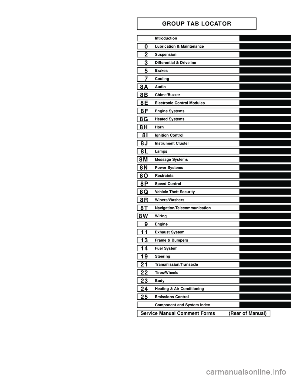
GROUP TAB LOCATOR
Introduction
0Lubrication & Maintenance
2Suspension
3Differential & Driveline
5Brakes
7Cooling
8AAudio
8BChime/Buzzer
8EElectronic Control Modules
8FEngine Systems
8GHeated Systems
8HHorn
8IIgnition Control
8JInstrument Cluster
8LLamps
8MMessage Systems
8NPower Systems
8ORestraints
8PSpeed Control
8QVehicle Theft Security
8RWipers/Washers
8TNavigation/Telecommunication
8WWiring
9Engine
11Exhaust System
13Frame & Bumpers
14Fuel System
19Steering
21Transmission/Transaxle
22Tires/Wheels
23Body
24Heating & Air Conditioning
25Emissions Control
Component and System Index
Service Manual Comment Forms (Rear of Manual)
Page 158 of 2339

(6) Remove screw securing engine coolant filler
tube to battery tray.
(7) If the vehicle is equipped with speed control,
disconnect the vacuum hose at the vacuum tank built
into the battery tray.
(8) Remove the two nuts and one bolt securing bat-
tery tray in place. Remove battery tray.
(9) If vehicle is equipped with speed control:
(a) Disconnect wiring harness connector from
the speed control servo.
(b) Remove the two servo mounting nuts.
(c) Lay speed control servo off to the side, out of
the way.
(10) Remove the wiper module (unit). (Refer to 8 -
ELECTRICAL/WIPERS/WASHERS/WIPER MOD-
ULE - REMOVAL)
(11) Disconnect wiring harness connector from
brake fluid level switch in master cylinder fluid res-
ervoir (Fig. 66).
CAUTION: Before removing the master cylinder
from the power brake vacuum booster, the master
cylinder and vacuum booster must be thoroughly
cleaned. This must be done to prevent dirt particles
from falling into the power brake vacuum booster.
(12) Clean area where master cylinder assembly
attaches to power brake booster. Use only a solvent
such as MopartBrake Parts Cleaner or equivalent.(13) Disconnect primary and secondary brake
tubes from ABS integrated control unit or non-ABS
junction block (Fig. 67). Install sealing plugs in the
now open brake tube ports and install caps on ends
of tubes.
NOTE: It is not necessary to remove the brake
tubes from the master cylinder when removing the
master cylinder from the vacuum booster.
(14) Remove two nuts attaching master cylinder to
power brake booster (Fig. 67).
(15) Slide master cylinder straight out of power
brake booster. Remove master cylinder with primary
and secondary tubes from vehicle.
CAUTION: A seal on the rear of the master cylinder
is used to create the seal for holding vacuum in the
power brake vacuum booster. The vacuum seal on
the master cylinder MUST be replaced whenever the
master cylinder is removed from the power brake
vacuum booster.
(16) Disconnect vacuum hose from check valve
located on vacuum booster.DO NOT REMOVE
CHECK VALVE FROM POWER BRAKE
BOOSTER.
Fig. 66 Master Cylinder And Booster
1 - POWER BRAKE BOOSTER
2 - BOOSTER IDENTIFICATION LABEL
3 - FLUID LEVEL SWITCH CONNECTOR
4 - PRIMARY BRAKE TUBE NUT
5 - SECONDARY BRAKE TUBE NUT
6 - MASTER CYLINDER
Fig. 67 Master Cylinder Mounting
1 - MASTER CYLINDER MOUNTING NUTS
2 - MASTER CYLINDER
3 - SECONDARY TUBE NUT AT ICU
4 - PRIMARY TUBE NUT AT ICU
RSBRAKES - BASE5-47
POWER BRAKE BOOSTER (Continued)
Page 162 of 2339

CAUTION: Do not reuse the original brake lamp
switch. The switch can only be adjusted once. That
is during initial installation of the switch. If the
switch is not adjusted properly or has been
removed for some service, a new switch must be
installed and adjusted.
(5) Remove and replace the brake lamp switch
with a NEW switch. (Refer to 8 - ELECTRICAL/
LAMPS/LIGHTING - EXTERIOR/BRAKE LAMP
SWITCH - REMOVAL), (Refer to 8 - ELECTRICAL/
LAMPS/LIGHTING - EXTERIOR/BRAKE LAMP
SWITCH - INSTALLATION)
(6) Install the silencer panel below the steering
column.
(7) Connect vacuum hose to check valve on power
brake booster.
CAUTION: The master cylinder (and its rear seal) is
used to create the seal for holding vacuum in the
vacuum booster. The vacuum seal on the master
cylinder MUST be replaced with a NEW seal when-
ever the master cylinder is removed from the vac-
uum booster.
CAUTION: When removing the vacuum seal from
the master cylinder do not use a sharp tool.
(8) Using a soft tool such as a trim stick, remove
the vacuum seal from the master cylinder mounting
flange.
(9) Install a NEW vacuum seal on rear mounting
flange of the master cylinder (Fig. 77).
(10) Position master cylinder on studs of booster,
aligning push rod on booster with master cylinder
piston.(11) Install the two nuts mounting the master cyl-
inder to the booster (Fig. 67). Tighten both mounting
nuts to a torque of 25 N´m (225 in. lbs.).
(12) Connect wiring harness connector to brake
fluid level switch in the master cylinder fluid reser-
voir (Fig. 66).
(13) Connect primary and secondary brake tubes
to ABS ICU or non-ABS junction block (Fig. 67).
Tighten the tube nuts to 17 N´m (145 in lbs.).
(14) Install wiper module (unit). (Refer to 8 -
ELECTRICAL/WIPERS/WASHERS/WIPER MOD-
ULE - INSTALLATION)
(15) If equipped with speed control, install speed
control servo and connect wiring connector. Tighten
the mounting nuts to a torque of 14 N´m (124 in.
lbs.).
(16) Install the battery tray. Install the two nuts
and one bolt attaching the battery tray to the vehicle.
Tighten the bolt and nuts to a torque of 14 N´m (124
in. lbs.).
(17) If vehicle is equipped with speed control, con-
nect the servo vacuum hose to the vacuum tank on
the battery tray.
(18) Install the air inlet resonator and hoses as an
assembly on the throttle body and air cleaner hous-
ing. Securely tighten hose clamp at air cleaner hous-
ing and throttle body.
(19) Secure the engine coolant filler neck to the
battery tray with its mounting screw.
(20) Install the battery, clamp and mounting nut.
(21) Install the positive battery cable on the bat-
tery.
(22) Install the negative battery cable on the bat-
tery.
(23) Install the battery thermal guard shield.
(24) Bleed the base brakes as necessary. (Refer to
5 - BRAKES - STANDARD PROCEDURE)
(25) Road test vehicle to ensure operation of the
brakes.
INSTALLATION - RHD
(1) Position power brake booster on dash panel
using the reverse procedure of its removal (Fig. 75).
(2) Below instrument panel, first install the two
upper nuts mounting the booster to the dash panel,
drawing it into place, then install the two lower
mounting nuts. Tighten the mounting nuts to a
torque of 29 N´m (250 in. lbs.).
(3) Using lubriplate, or equivalent, coat the sur-
face of the brake pedal torque shaft pin where it con-
tacts the booster input rod.
CAUTION: When installing the brake pedal torque
shaft pin on the power brake booster input rod, do
not re-use the old retaining clip.
Fig. 77 Vacuum Seal (Typical)
1 - MASTER CYLINDER ASSEMBLY
2 - VACUUM SEAL
RSBRAKES - BASE5-51
POWER BRAKE BOOSTER (Continued)
Page 387 of 2339
LAMPS/LIGHTING - EXTERIOR
DESCRIPTION
LAMP SYSTEMS
Lighting circuits are protected by fuses. Lighting
circuits require an overload protected power and high
side drivers source, ON/OFF device, lamps and body
grounds to operate properly. Plastic lamps require a
wire in the harness to supply body ground to the
lamp socket. Replace sockets and bulbs that are cor-
roded.
Some of the interior and exterior lighting functions
are governed by the Body Control Module (BCM).
The headlamp, dome, and the door ajar switches pro-
vide signals to the BCM. The BCM in turn sends a
Programmable Communication Interface (PCI) bus
message to the Front Control Module (FCM) to
enable the necessary drivers to set the required illu-
mination configuration.
Wire connectors can make intermittent contact or
become corroded. Before coupling wire connectors,
inspect the terminals inside the connector. Male ter-
minals should not be bent or disengaged from the
insulator. Female terminals should not be sprung
open or disengaged from the insulator. Bent and
sprung terminals can be repaired using needle nose
pliers and pick tool. Corroded terminals appear
chalky or green. Corroded terminals should be
replaced to avoid recurrence of the problem symp-
toms.
Begin electrical system failure diagnosis by testing
related fuses in the fuse block and intelligent power
module. Verify that bulbs are in good condition and
test continuity of the circuit ground. Refer to the
appropriate wiring information.
AUTOMATIC HEADLAMP SYSTEM
The Automatic Headlamp system turns the instru-
mentation and exterior illumination lamps ON when
the ambient light levels are Night and the engine
RPM is 450 or above, and OFF when light levels are
Day.
DAYTIME RUNNING LAMPS
Operating the high-beam headlamps at reduced
power provides daytime running lamps, which are
required on all new Canadian vehicles. Daytime run-
ning lamps are functional when 450 rpm's are
reached.
HEADLAMPS ON WITH WINDSHIELD WIPERS
For vehicles equipped with the Automatic Head-
lamp System, the instrumentation and exterior illu-
mination lamps will be turned ON when the
headlamp switch is in the AUTO position, RPM >450 and the windshield wipers have been in the
intermittent, low or high mode of operation for more
than ten seconds. When the windshield wipers are
turned OFF the Body Control Module will determine
if the instrumentation and exterior illumination
lamps should remain ON base upon the current
ambient light level.
HEADLAMP SYSTEM
The configuration of the headlamp system of head-
lamps, park lamps and fog lamps is determined by
the BCM. The BCM determines the lighting configu-
ration as a result of the inputs from the ignition
switch, headlamp switch and multi-function switch. A
PCI bus is transmitted from the BCM to the FCM to
enable the necessary drivers to set the illumination
configuration. Four wires are connected between the
headlamp switch and the BCM. The first wire con-
tains information regarding the position of the head-
lamp switch (Off, Automatic Headlamps, Automatic
Headlamp switch fog, Park with Fog, Head, or Head
with Fog Lamps). The second wire contains informa-
tion regarding the position of the dimmer switch
(Dome Lamp, Daytime Brightness, Dimming Level or
Off). The third wire is a dedicated signal return
(ground) wire. The fourth wire provides power to the
front fog lamp indicator.
HEADLAMP TIME DELAY SYSTEM
The headlamp time delay system is controlled by
the Body Control Module (BCM) via a PCI bus mes-
sage transmitted by the BCM to the FCM to turn off
the headlamps.
OPERATION
AUTOMATIC HEADLAMP SYSTEM
Automatic headlamps are controlled by the Body
Control Module (BCM). With the headlamp switch in
the AUTO position, the BCM will control the head-
lamp, parking, side marker, tail and instrumentation
lamps based on ambient light levels. Ambient light
levels are monitored by the BCM using the Day/
Night signal and Electrochromatic Mirror (ECM)
present from the Compass Mini Trip (CMTC) located
on the front windshield in front of the rear view mir-
ror ECM. Ambient light readings are averaged to
limit cycling the lamps ON and OFF when passing
through areas with varying light levels. The auto-
matic headlamps will only function when the engine
is running with RPM > 450. When the headlamp
switch is in the AUTO position (Automatic mode), the
Headlamp Time Delay system will function when the
ignition switch is placed in any position other than
run/start.
8L - 2 LAMPS/LIGHTING - EXTERIORRS
Page 418 of 2339
²RETRAIN TIRE SENSORS?- This program-
mable feature only applies to vehicles equipped with
the optional Tire Pressure Monitoring System. The
options include Yes and No. The default is No. When
Yes is selected, and the menu button is depressed the
EVIC will enter the training mode, starting with the
left front tire.
²USE FACTORY SETTINGS?- The options
include Yes and No. The default is Yes. When yes is
selected all the programmable features will return to
there defaults and the rest of the programmable fea-
tures will not be displayed. If No is selected the rest
of the programmable features will be displayed at
there current chosen values. This feature will auto-
matically return to the Yes default under two condi-
tions. First, if no programmable features are changed
from there defaults. Second, if all the programmable
features equal there defaults.
²AUTO DOOR LOCKS?- The options include
Yes and No. The default is Yes. When Yes is selected,
all doors and the liftgate lock automatically when
vehicle speed reaches 25 kilometers-per-hour (15
miles-per-hour). If YES is selected, a second program-
mable feature appears,AUTO UNLOCK ON EXIT?
- The options again include Yes and No. The default
is No. When Yes is selected, following each Auto Door
Lock event all doors and the liftgate will automati-
cally unlock when the driver door is opened, if the
vehicle is stopped and the transmission gear selector
is in Park or Neutral. The Auto Door Unlock event
will only occur once following each Auto Door Lock
event.
²REMOTE UNLOCK- The options include
Driver Door 1st and All Doors. The default is Driver
Door 1st. When Diver Door 1st is selected, only the
driver door unlocks when the Unlock button of the
Remote Keyless Entry (RKE) transmitter is
depressed once. The Unlock button of the RKE trans-
mitter must be depressed twice to unlock all doors.
When All Doors is selected, all doors unlock when the
Unlock button of the RKE transmitter is depressed
once.
²REMOTE LINKED TO MEMORY?- This pro-
grammable feature only applies to vehicles equipped
with the optional memory / heated system. The
options include Yes and No. The default is No. When
Yes is selected, the memory system will recall the
Driver 1 or Driver 2 memory settings assigned to the
RKE transmitter being used to unlock the vehicle.
When No is selected, the memory system will only
recall memory settings when the Driver 1 or Driver 2
push buttons of the memory switch on the driver side
front door trim panel are depressed.
²SOUND HORN ON LOCK?- The options
include Yes and No. The default is No. When Yes is
selected, a short horn chirp will provide an audibleconfirmation when the RKE receiver recognizes a
valid Lock signal from an RKE transmitter. When No
is selected, no horn chirp will occur with the RKE
Lock event. This feature may be selected indepen-
dent of theFLASH LIGHTS WITH LOCKS?pro-
grammable feature.
²FLASH LIGHTS WITH LOCKS?- The options
include Yes and No. The default is Yes. When Yes is
selected, a single flash of the hazard warning lamps
will provide an optical confirmation when the RKE
receiver recognizes a valid Lock signal from an RKE
transmitter, and two flashes of the same lamps will
occur when the RKE receiver recognizes a valid
Unlock signal from an RKE transmitter. When No is
selected, no lamp flash will occur with the RKE Lock
or Unlock event. This feature may be selected inde-
pendent of theSOUND HORN ON LOCK?pro-
grammable feature.
²HEADLAMP DELAY =- The options include
Off, 30 Sec, 60 Sec, and 90 Sec. The default is 90 Sec.
When a time interval is selected, the headlamps will
remain on for that length of time when the head-
lamps are turned off after the ignition is turned off,
or if the Auto mode is selected on vehicles with the
Auto Headlamps option. When Off is selected, the
headlamp delay feature is disabled.
²HEADLAMPS ON WITH WIPERS?- This pro-
grammable feature only applies to vehicles equipped
with the optional Auto Headlamps. The options
include Yes and No. The default is No. When Yes is
selected, the headlamps will turn on automatically
when the windshield wipers are turned on. The head-
lamps will turn off when the wipers are turned off,
as long as the headlamp switch is in the Auto or Off
positions. When No is selected, the headlamps will
only turn on if manually selected or if the Auto mode
is selected and the outside ambient light levels dic-
tate that they should be on.
²POWER ACCESSORY DELAY?- The options
include Yes and No. The default is Yes. When No is
selected, the accessory powered components will turn
off automatically when the ignition key is turned off.
When Yes is selected, the accessory powered compo-
nents will remain on for 45 seconds when the igni-
tion key is turned off.
REMOVAL
(1) Disconnect and isolate the battery negative
cable.
(2) Remove overhead console. (Refer to 8 - ELEC-
TRICAL/OVERHEAD CONSOLE - REMOVAL).
(3) Remove the ten screws holding the Electronic
Vehicle Information Center (EVIC) module in the
overhead console.
(4) Remove EVIC module from console assembly.
RSOVERHEAD CONSOLE8M-9
ELECTRONIC VEHICLE INFO CENTER (Continued)
Page 546 of 2339
WIPERS/WASHERS
TABLE OF CONTENTS
page page
WIPERS/WASHERS
DESCRIPTION..........................1
OPERATION............................2
DIAGNOSIS AND TESTING
DIAGNOSIS AND TESTING - FRONT WIPER
SYSTEM.............................2
DIAGNOSIS AND TESTING - FRONT
WIPER/WASHER SWITCH................2
DIAGNOSIS AND TESTING - FAILED PARK
SWITCH.............................2
DIAGNOSIS AND TESTING - REAR WIPER
SYSTEM.............................4
DIAGNOSIS AND TESTING - WASHER
SYSTEM.............................5
FRONT WIPER ARMS
STANDARD PROCEDURE - FRONT WIPER
ARM ALIGNMENT......................9
REMOVAL.............................9
INSTALLATION..........................9
FRONT WIPER MOTOR
REMOVAL.............................9
INSTALLATION.........................10
REAR WIPER ARM
REMOVAL.............................10
INSTALLATION.........................10
REAR WIPER MOTOR
REMOVAL.............................10INSTALLATION.........................10
REAR WIPER/WASHER SWITCH
DESCRIPTION.........................10
OPERATION...........................11
WASHER FLUID LEVEL SWITCH
REMOVAL.............................11
INSTALLATION.........................11
WASHER HOSES
REMOVAL.............................11
INSTALLATION.........................12
WASHER PUMP MOTOR
REMOVAL.............................12
INSTALLATION.........................12
WASHER RESERVOIR
REMOVAL.............................12
INSTALLATION.........................13
WIPER BLADES
REMOVAL.............................13
CLEANING............................13
INSTALLATION.........................13
WIPER LINKAGE
REMOVAL.............................13
INSTALLATION.........................14
WIPER MODULE
REMOVAL.............................14
INSTALLATION.........................14
WIPERS/WASHERS
DESCRIPTION
FRONT WIPER/WASHER SYSTEM
The windshield wipers can be operated with the
windshield wiper switch when the ignition switch is
in the RUN or ACCESSORY positions. The wind-
shield wiper system is protected by a 30 amp fuse (9)
located in the Power Distribution Center (PDC) part
of the Integrated Power Module (IPM) in the engine
compartment. The wiper/washer switch is integral to
the multi-function switch. It is a resistive MUX
switch that sends inputs to the BCM to operate the
wiper/washer system.
REAR WIPER/WASHER SYSTEM
The rear windshield wiper and washers can be
operated when the ignition switch is in the RUN
position.
If equipped with Manual Temperature Controls
(MTC), the rear wiper/washer switch is integral to
the HVAC control unit. It replaces what was formerly
the ON/OFF switch. If equipped with Automatic Tem-
perature Controls (ATC), the rear wiper/washer
switch is located on the accessory switch panel in the
center stack of the instrument panel.
RSWIPERS/WASHERS8R-1
Page 547 of 2339
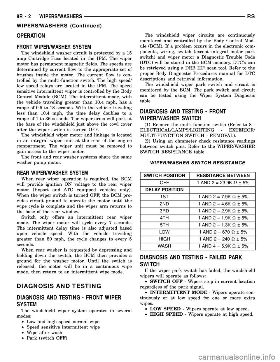
OPERATION
FRONT WIPER/WASHER SYSTEM
The windshield washer circuit is protected by a 15
amp Cartridge Fuse located in the IPM. The wiper
motor has permanent magnetic fields. The speeds are
determined by current flow to the appropriate set of
brushes inside the motor. The current flow is con-
trolled by the multi-function switch. The high speed/
low speed relays are located in the IPM. The speed
sensitive intermittent wiper is controlled by the Body
Control Module (BCM). The intermittent mode, with
the vehicle traveling greater than 10.4 mph, has a
range of 0.5 to 18 seconds. With the vehicle traveling
less than 10.4 mph, the time delay doubles to a
range of 1 to 36 seconds. The wiper arms will park at
the base of the windshield just above the cowl cover
after the wiper switch is turned OFF.
The windshield wiper motor and linkage is located
in an integral wiper unit at the rear of the engine
compartment. The wiper unit must be removed to
gain access to the wiper motor.
The front and rear washer systems share the same
washer pump motor.
REAR WIPER/WASHER SYSTEM
When rear wiper operation is required, the BCM
will provide ignition ON voltage to the rear wiper
motor (Export and ATC equipped vehicles only).
When the wiper switch is turned OFF, the BCM pro-
vides circuit ground to operate the motor until the
wipe cycle is complete and the wiper arm returns to
the base of the rear window.
Switch only offers an intermittent rear wiper
mode. The wiper motor will cycle every 7 seconds.
The intermittent delay time is also adjusted based
upon vehicle speed. With the vehicle traveling
greater than 50 mph, the cycle changes to every 5
seconds.
When rear washer is requested by depressing and
holding down the switch, the BCM then provides a
ground for the washer motor. Until the switch is
released, the motor will be in a continuous wipe
mode, then return to an intermittent wipe mode.
DIAGNOSIS AND TESTING
DIAGNOSIS AND TESTING - FRONT WIPER
SYSTEM
The windshield wiper system operates in several
modes:
²Low and high speed normal wipe
²Speed sensitive intermittent wipe
²Wipe after wash
²Park (switch OFF)The windshield wiper circuits are continuously
monitored and controlled by the Body Control Mod-
ule (BCM). If a problem occurs in the electronic com-
ponents, wiring, switch (except integral motor park
switch) and wiper motor a Diagnostic Trouble Code
(DTC) will be stored in the BCM memory. DTC's can
be retrieved using a DRB IIItscan tool. Refer to the
proper Body Diagnostic Procedures manual for DTC
descriptions and retrieval information.
The windshield wiper park switch and circuit is
monitored by the BCM. The park switch and circuit
can be tested using the Wiper System Diagnosis
table.
DIAGNOSIS AND TESTING - FRONT
WIPER/WASHER SWITCH
(1) Remove the multi-function switch (Refer to 8 -
ELECTRICAL/LAMPS/LIGHTING - EXTERIOR/
MULTI-FUNCTION SWITCH - REMOVAL).
(2) Using an ohmmeter check resistance readings
between switch pins. Refer to the WIPER/WASHER
SWITCH RESISTANCE table.
WIPER/WASHER SWITCH RESISTANCE
SWITCH POSITION RESISTANCE BETWEEN
OFF 1 AND 2 = 23.9KV 5%
DELAY POSITION
1ST 1 AND 2 = 7.9KV 5%
2ND 1 AND 2 = 4.6KV 5%
3RD 1 AND 2 = 2.9KV 5%
4TH 1 AND 2 = 1.9KV 5%
5TH 1 AND 2 = 1.3KV 5%
LOW 1 AND 2 = 670V 5%
HIGH 1 AND2=240V 5%
WASH 1 AND 4 = 5.9KV 5%
DIAGNOSIS AND TESTING - FAILED PARK
SWITCH
If the wiper park switch has failed, the windshield
wipers will operate as follows:
²SWITCH OFF- Wipers stop in current location
regardless of the park signal.
²INTERMITTENT MODE- Wipers operate con-
tinuously or at low speed for one or more extra
wipes.
²LOW SPEED- Wipers operate at low speed.
²HIGH SPEED- Wipers operate at high speed.
8R - 2 WIPERS/WASHERSRS
WIPERS/WASHERS (Continued)
Page 548 of 2339
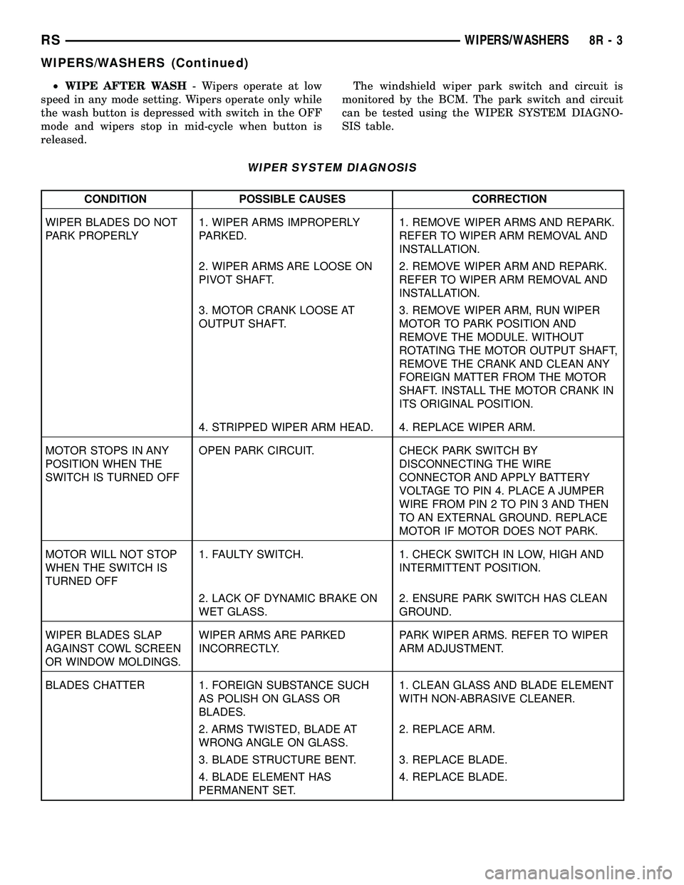
²WIPE AFTER WASH- Wipers operate at low
speed in any mode setting. Wipers operate only while
the wash button is depressed with switch in the OFF
mode and wipers stop in mid-cycle when button is
released.The windshield wiper park switch and circuit is
monitored by the BCM. The park switch and circuit
can be tested using the WIPER SYSTEM DIAGNO-
SIS table.
WIPER SYSTEM DIAGNOSIS
CONDITION POSSIBLE CAUSES CORRECTION
WIPER BLADES DO NOT
PARK PROPERLY1. WIPER ARMS IMPROPERLY
PARKED.1. REMOVE WIPER ARMS AND REPARK.
REFER TO WIPER ARM REMOVAL AND
INSTALLATION.
2. WIPER ARMS ARE LOOSE ON
PIVOT SHAFT.2. REMOVE WIPER ARM AND REPARK.
REFER TO WIPER ARM REMOVAL AND
INSTALLATION.
3. MOTOR CRANK LOOSE AT
OUTPUT SHAFT.3. REMOVE WIPER ARM, RUN WIPER
MOTOR TO PARK POSITION AND
REMOVE THE MODULE. WITHOUT
ROTATING THE MOTOR OUTPUT SHAFT,
REMOVE THE CRANK AND CLEAN ANY
FOREIGN MATTER FROM THE MOTOR
SHAFT. INSTALL THE MOTOR CRANK IN
ITS ORIGINAL POSITION.
4. STRIPPED WIPER ARM HEAD. 4. REPLACE WIPER ARM.
MOTOR STOPS IN ANY
POSITION WHEN THE
SWITCH IS TURNED OFFOPEN PARK CIRCUIT. CHECK PARK SWITCH BY
DISCONNECTING THE WIRE
CONNECTOR AND APPLY BATTERY
VOLTAGE TO PIN 4. PLACE A JUMPER
WIRE FROM PIN 2 TO PIN 3 AND THEN
TO AN EXTERNAL GROUND. REPLACE
MOTOR IF MOTOR DOES NOT PARK.
MOTOR WILL NOT STOP
WHEN THE SWITCH IS
TURNED OFF1. FAULTY SWITCH. 1. CHECK SWITCH IN LOW, HIGH AND
INTERMITTENT POSITION.
2. LACK OF DYNAMIC BRAKE ON
WET GLASS.2. ENSURE PARK SWITCH HAS CLEAN
GROUND.
WIPER BLADES SLAP
AGAINST COWL SCREEN
OR WINDOW MOLDINGS.WIPER ARMS ARE PARKED
INCORRECTLY.PARK WIPER ARMS. REFER TO WIPER
ARM ADJUSTMENT.
BLADES CHATTER 1. FOREIGN SUBSTANCE SUCH
AS POLISH ON GLASS OR
BLADES.1. CLEAN GLASS AND BLADE ELEMENT
WITH NON-ABRASIVE CLEANER.
2. ARMS TWISTED, BLADE AT
WRONG ANGLE ON GLASS.2. REPLACE ARM.
3. BLADE STRUCTURE BENT. 3. REPLACE BLADE.
4. BLADE ELEMENT HAS
PERMANENT SET.4. REPLACE BLADE.
RSWIPERS/WASHERS8R-3
WIPERS/WASHERS (Continued)
Page 549 of 2339
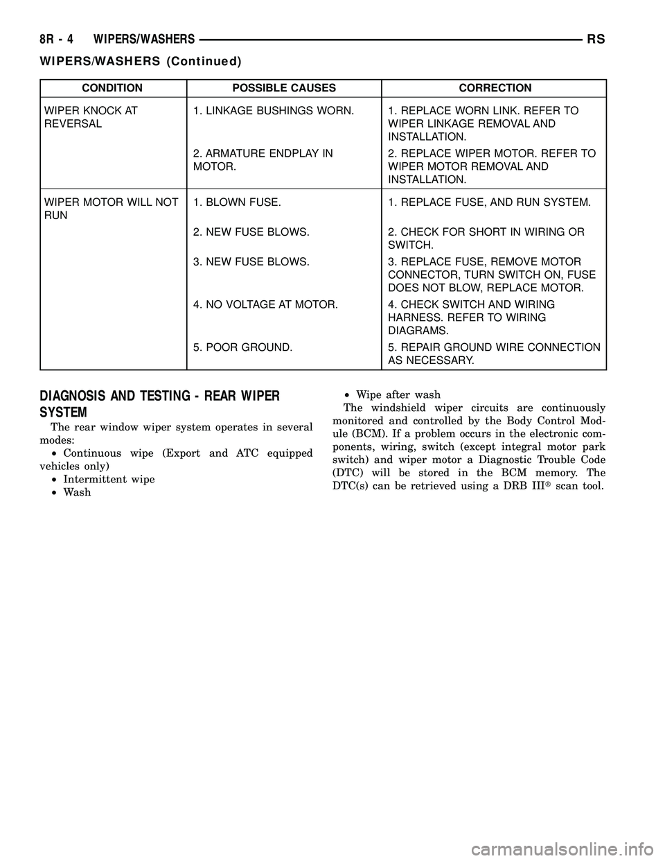
CONDITION POSSIBLE CAUSES CORRECTION
WIPER KNOCK AT
REVERSAL1. LINKAGE BUSHINGS WORN. 1. REPLACE WORN LINK. REFER TO
WIPER LINKAGE REMOVAL AND
INSTALLATION.
2. ARMATURE ENDPLAY IN
MOTOR.2. REPLACE WIPER MOTOR. REFER TO
WIPER MOTOR REMOVAL AND
INSTALLATION.
WIPER MOTOR WILL NOT
RUN1. BLOWN FUSE. 1. REPLACE FUSE, AND RUN SYSTEM.
2. NEW FUSE BLOWS. 2. CHECK FOR SHORT IN WIRING OR
SWITCH.
3. NEW FUSE BLOWS. 3. REPLACE FUSE, REMOVE MOTOR
CONNECTOR, TURN SWITCH ON, FUSE
DOES NOT BLOW, REPLACE MOTOR.
4. NO VOLTAGE AT MOTOR. 4. CHECK SWITCH AND WIRING
HARNESS. REFER TO WIRING
DIAGRAMS.
5. POOR GROUND. 5. REPAIR GROUND WIRE CONNECTION
AS NECESSARY.
DIAGNOSIS AND TESTING - REAR WIPER
SYSTEM
The rear window wiper system operates in several
modes:
²Continuous wipe (Export and ATC equipped
vehicles only)
²Intermittent wipe
²Wash²Wipe after wash
The windshield wiper circuits are continuously
monitored and controlled by the Body Control Mod-
ule (BCM). If a problem occurs in the electronic com-
ponents, wiring, switch (except integral motor park
switch) and wiper motor a Diagnostic Trouble Code
(DTC) will be stored in the BCM memory. The
DTC(s) can be retrieved using a DRB IIItscan tool.
8R - 4 WIPERS/WASHERSRS
WIPERS/WASHERS (Continued)
Page 550 of 2339

DIAGNOSIS AND TESTING - WASHER SYSTEM
WASHER SYSTEM DIAGNOSIS
CONDITION POSSIBLE CAUSES CORRECTION
WASHER MOTOR 1. IPM FUSE #33 BLOWN OR
DEFECTIVE.1. CHECK FUSE #33 IN THE IPM.
REPLACE IF NOT OK.
2. IPM FUSE #33 LOOSE. 2. PROPERLY INSTALL IPM FUSE #33 IN
SOCKET.
BLOWN FUSE WHEN
IGNITION SWITCH IS IN
THE RUN OR ACCESSORY
POSITION.1. SHORT IN IPM BETWEEN
FUSE #33 AND PIN 11 OR PIN
1.1. REFER TO IPM DIAGNOSTIC
PROCEDURES IN WIRING DIAGRAMS.
2. SHORT IN MOTOR POWER
CIRCUIT.2. SHORT OR DEFECTIVE CIRCUIT
BETWEEN IPM PIN 11 AND WASHER
MOTOR CONNECTOR POSITIVE
TERMINAL 2. IF NOT OK, REPAIR CIRCUIT.
3. SHORT IN WASHER PUMP
MOTOR.3. REPLACE WASHER PUMP MOTOR.
WASHER MOTOR RUNS
WHEN IGNITION SWITCH
IN RUN OR ACCESSORY
POSITION.1. SHORT IN IPM BETWEEN
WASHER PUMP MOTOR LSD
AND PIN 20.1. REFER TO IPM DIAGNOSTIC
PROCEDURES IN WIRING DIAGRAMS.
2. DEFECTIVE FRONT
WASHER LSD IN IPM.2. REFER TO IPM DIAGNOSTIC
PROCEDURES IN WIRING DIAGRAMS.
3. SHORT IN MOTOR GROUND
CIRCUIT.3. SHORT OR DEFECTIVE CIRCUIT
BETWEEN IPM PIN 20 AND MOTOR
CONNECTOR NEGATIVE TERMINAL 1. IF
NOT OK, REPAIR CIRCUIT.
RSWIPERS/WASHERS8R-5
WIPERS/WASHERS (Continued)