horn CHRYSLER CROSSFIRE 2007 1.G Owners Manual
[x] Cancel search | Manufacturer: CHRYSLER, Model Year: 2007, Model line: CROSSFIRE, Model: CHRYSLER CROSSFIRE 2007 1.GPages: 299, PDF Size: 8.26 MB
Page 17 of 299

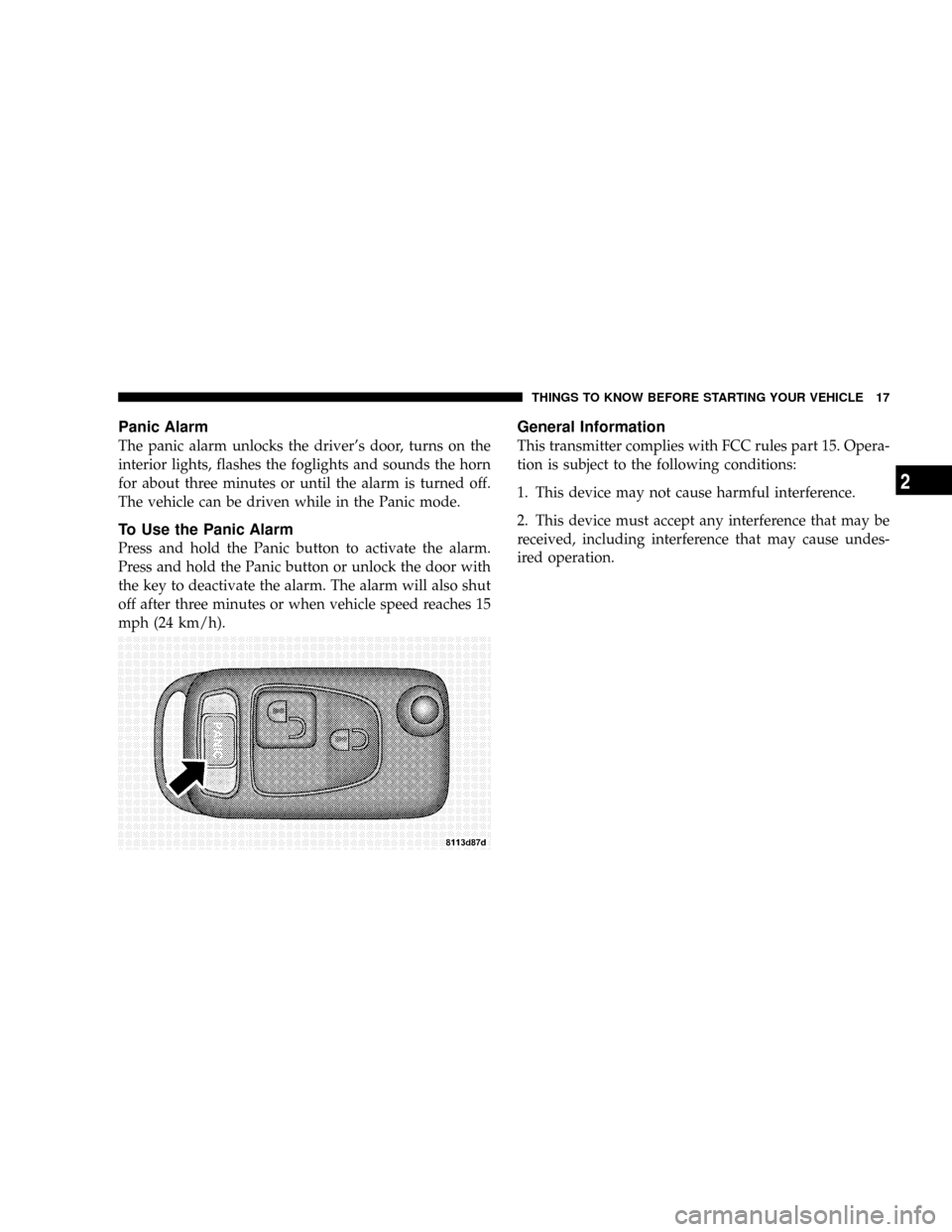
Panic Alarm
The panic alarm unlocks the driver's door, turns on the
interior lights, flashes the foglights and sounds the horn
for about three minutes or until the alarm is turned off.
The vehicle can be driven while in the Panic mode.
To Use the Panic Alarm
Press and hold the Panic button to activate the alarm.
Press and hold the Panic button or unlock the door with
the key to deactivate the alarm. The alarm will also shut
off after three minutes or when vehicle speed reaches 15
mph (24 km/h).
General Information
This transmitter complies with FCC rules part 15. Opera-
tion is subject to the following conditions:
1. This device may not cause harmful interference.
2. This device must accept any interference that may be
received, including interference that may cause undes-
ired operation.
THINGS TO KNOW BEFORE STARTING YOUR VEHICLE 17
2
Page 255 of 299

Underhood Accessory Fuse Block Fuses
Cavity Fuse Circuits
1 5 Amp
BeigeGarage Door Opening Signal,
Tire Pressure Control and Seat
Heater
2 5 Amp
BeigeControl Unit Airbag
3 5 Amp
BeigeIndicator, Safety Restraint System
and Indicator Passenger Airbag
Off
4 7.5 Amp
BrownHeated Mirror
5 15 Amp
BlueRadio (Coupe)
5 25 Amp
WhiteRoof Control Module (Roadster)
6 5 Amp
BeigeExterior Mirror Adjustment, Left
And Right (Coupe)
6 40 Amp
OrangeRoof Hydraulic Unit (Roadster)
7 5 Amp
BeigeOccupation Classification Module
(Right Seat)
Cavity Fuse Circuits
8 15 Amp
BlueRadio
9 5 Amp
BeigeControl Unit Airbag
10 5 Amp
BeigeSpeed Control
11 15 Amp
BlueIgnition Coil 6 Cyl.
12 10 Amp
RedWasher Liquid Heater, Washer
Nozzle Heater
13 10 Amp
RedRoof Light, Horn, Anti-Theft-
Alarm, Trunk Light and Tire
Pressure Control
14 10 Amp
RedDiagnostic Socket
15 5 Amp
BeigeClimate Control, Auxiliary Water
Pump
16 10 Amp
RedSpoiler Motor
17 40 Amp
OrangeElectronic Stability Program
MAINTAINING YOUR VEHICLE 255
7
Page 258 of 299

Cavity Fuse Circuits
5 15 Amp
BlueFuel Pump
6 15 Amp
BlueHorn
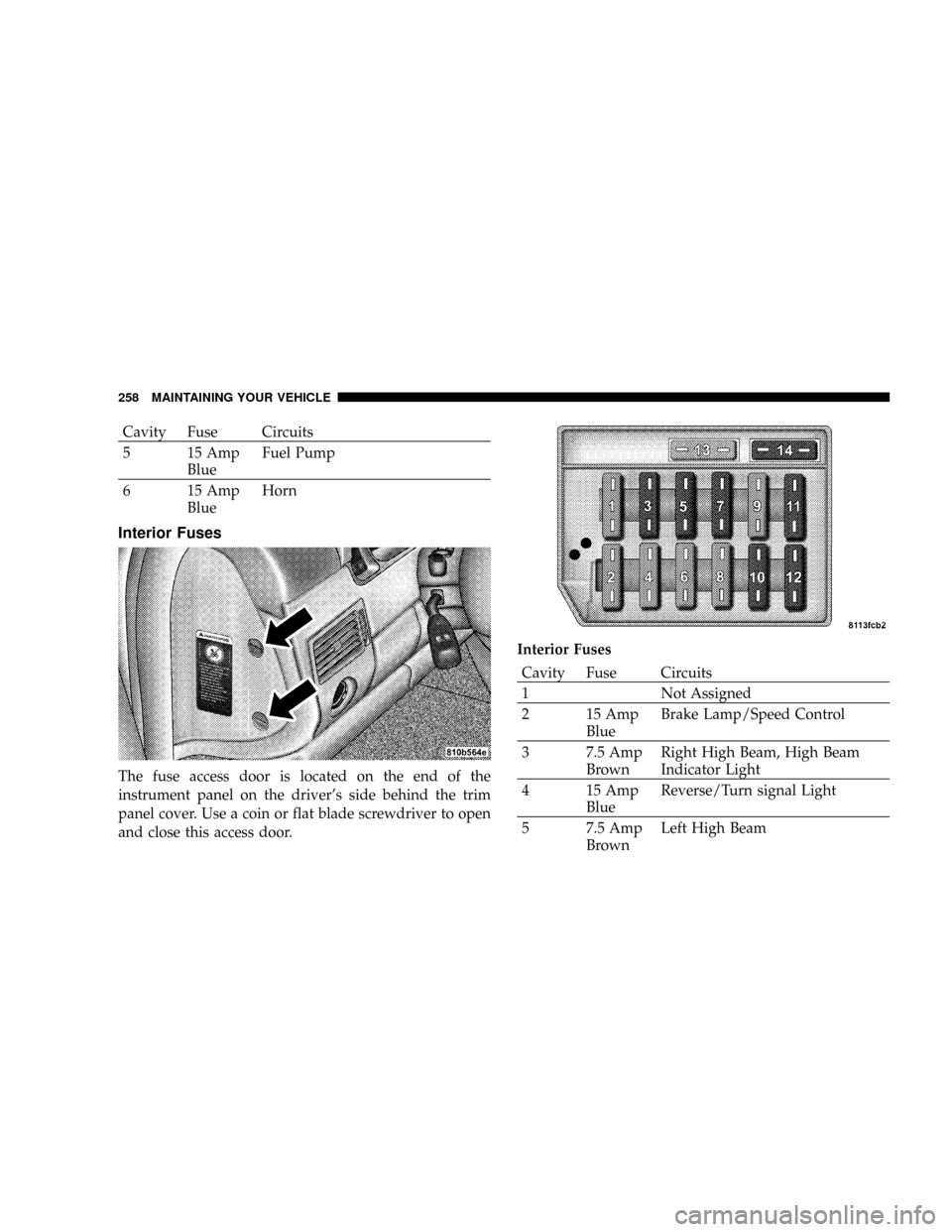
Interior Fuses
The fuse access door is located on the end of the
instrument panel on the driver's side behind the trim
panel cover. Use a coin or flat blade screwdriver to open
and close this access door.Interior Fuses
Cavity Fuse Circuits
1 Not Assigned
2 15 Amp
BlueBrake Lamp/Speed Control
3 7.5 Amp
BrownRight High Beam, High Beam
Indicator Light
4 15 Amp
BlueReverse/Turn signal Light
5 7.5 Amp
BrownLeft High Beam
258 MAINTAINING YOUR VEHICLE
Page 274 of 299

Your Flexible Service System (FSS) Ð see Understanding
Your Instrument Panel section Ð should give you an
exact indication of when your vehicle should be sched-
uled for service and which schedule to follow.
Additional Periodic Maintenanceitems should also be
performed beyond the items listed in the following charts
to assure the optimum performance of your Crossfire.
SCOPE OF WORK FOR ªAº SCHEDULE
MAINTENANCE SERVICE
Oil Change
²Change oil and replace filter
Maintenance
²Lubricate hood hinges, latch, and secondary latch
²Reset FSS Display
Function Check
²Horn, hazard warning flashers, turn signals, and indi-
cator lamps
²Headlamps and exterior lighting
²Windshield wipers and washer system
Inspection
²Check front and rear brake pads for lining thickness
²Check tires for damage and general condition
²Check tire inflation pressures and correct if necessary
Fluid Levels
Check fluid levels for the following systems and correct if
necessary. Should there be a loss of fluid that cannot be
explained by regular use, trace and eliminate the cause.
²Engine cooling system (check corrosion inhibitor/
antifreeze)
²Hydraulic brake system
²Power steering system
²Windshield washer system
274 MAINTENANCE SCHEDULES
8
M
A
I
N
T
E
N
A
N
C
E
S
C
H
E
D
U
L
E
S
Page 275 of 299

SCOPE OF WORK FOR ªBº SCHEDULE
MAINTENANCE SERVICE
Oil Change
²Change oil and replace filter
Maintenance
²Rotate tires
²Replace dust filter (if equipped)
²Lubricate hood hinges, latch, and secondary latch
²Reset FSS Display
Function Check
²Horn, hazard warning flashers, turn signals, and indi-
cator lamps
²Headlamps and exterior lighting
²Windshield wipers and washer system
²Check seat belts for damage and proper function
²Test hydraulic brakes and check parking brake func-
tionInspection
²Check front and rear brake pads for lining thickness
²Check condition of front and rear brake discs
²Check tires for damage and general condition
²Check tire inflation pressures and correct if necessary
²Check major underbody components for leakage or
damage (if there are signs of leakage, determine cause
and repair)
²Check condition of front axle ball joints and rubber
boots
²Check condition of steering components and rubber
boots
²Check underhood components for leakage or damage
(if there are signs of leakage determine cause and
repair)
²Check condition of accessory drive belt
²Check headlamp aiming, adjust if necessary
²Check windshield wiper blades, replace if necessary
MAINTENANCE SCHEDULES 275
8
M
A
I
N
T
E
N
A
N
C
E
S
C
H
E
D
U
L
E
S