engine CHRYSLER CROSSFIRE 2008 1.G Owners Manual
[x] Cancel search | Manufacturer: CHRYSLER, Model Year: 2008, Model line: CROSSFIRE, Model: CHRYSLER CROSSFIRE 2008 1.GPages: 358, PDF Size: 4.7 MB
Page 313 of 358
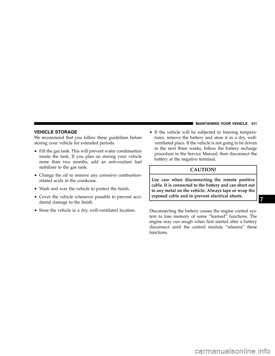
VEHICLE STORAGE
We recommend that you follow these guidelines before
storing your vehicle for extended periods.
²Fill the gas tank. This will prevent water condensation
inside the tank. If you plan on storing your vehicle
more than two months, add an anti-oxidant fuel
stabilizer to the gas tank.
²Change the oil to remove any corrosive combustion-
related acids in the crankcase.
²Wash and wax the vehicle to protect the finish.
²Cover the vehicle whenever possible to prevent acci-
dental damage to the finish.
²Store the vehicle in a dry, well-ventilated location.
²If the vehicle will be subjected to freezing tempera-
tures, remove the battery and store it in a dry, well-
ventilated place. If the vehicle is not going to be driven
in the next three weeks, follow the battery recharge
procedure in the Service Manual, then disconnect the
battery at the negative terminal.
CAUTION!
Use care when disconnecting the remote positive
cable. It is connected to the battery and can short out
to any metal on the vehicle. Always tape or wrap the
exposed cable end to prevent electrical shorts.
Disconnecting the battery causes the engine control sys-
tem to lose memory of some ªlearnedº functions. The
engine may run rough when first started after a battery
disconnect until the control module ªrelearnsº these
functions.
MAINTAINING YOUR VEHICLE 311
7
Page 315 of 358
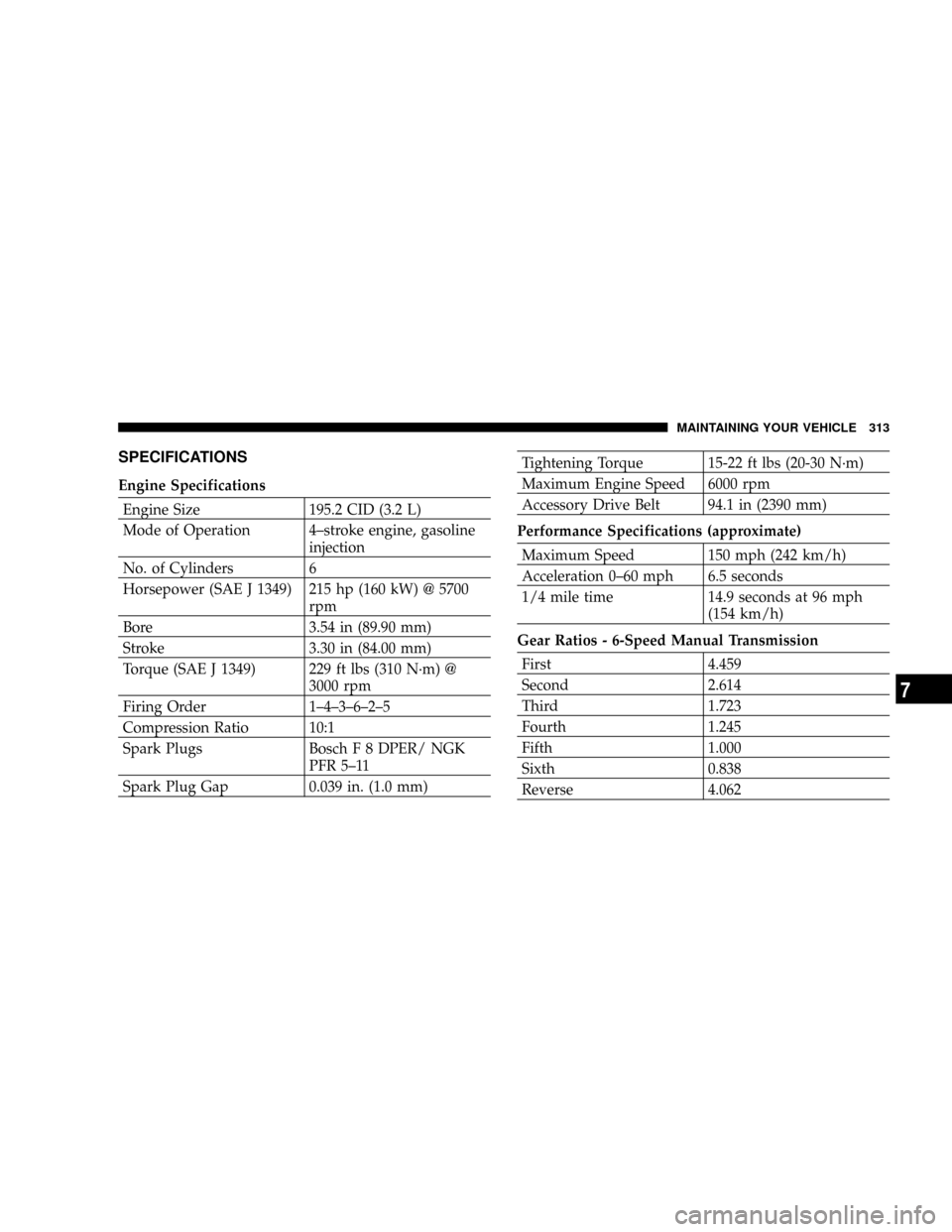
SPECIFICATIONS
Engine Specifications
Engine Size 195.2 CID (3.2 L)
Mode of Operation 4±stroke engine, gasoline
injection
No. of Cylinders 6
Horsepower (SAE J 1349) 215 hp (160 kW) @ 5700
rpm
Bore 3.54 in (89.90 mm)
Stroke 3.30 in (84.00 mm)
Torque (SAE J 1349) 229 ft lbs (310 N´m) @
3000 rpm
Firing Order 1±4±3±6±2±5
Compression Ratio 10:1
Spark Plugs Bosch F 8 DPER/ NGK
PFR 5±11
Spark Plug Gap 0.039 in. (1.0 mm)
Tightening Torque 15-22 ft lbs (20-30 N´m)
Maximum Engine Speed 6000 rpm
Accessory Drive Belt 94.1 in (2390 mm)
Performance Specifications (approximate)
Maximum Speed 150 mph (242 km/h)
Acceleration 0±60 mph 6.5 seconds
1/4 mile time 14.9 seconds at 96 mph
(154 km/h)
Gear Ratios - 6-Speed Manual Transmission
First 4.459
Second 2.614
Third 1.723
Fourth 1.245
Fifth 1.000
Sixth 0.838
Reverse 4.062
MAINTAINING YOUR VEHICLE 313
7
Page 317 of 358
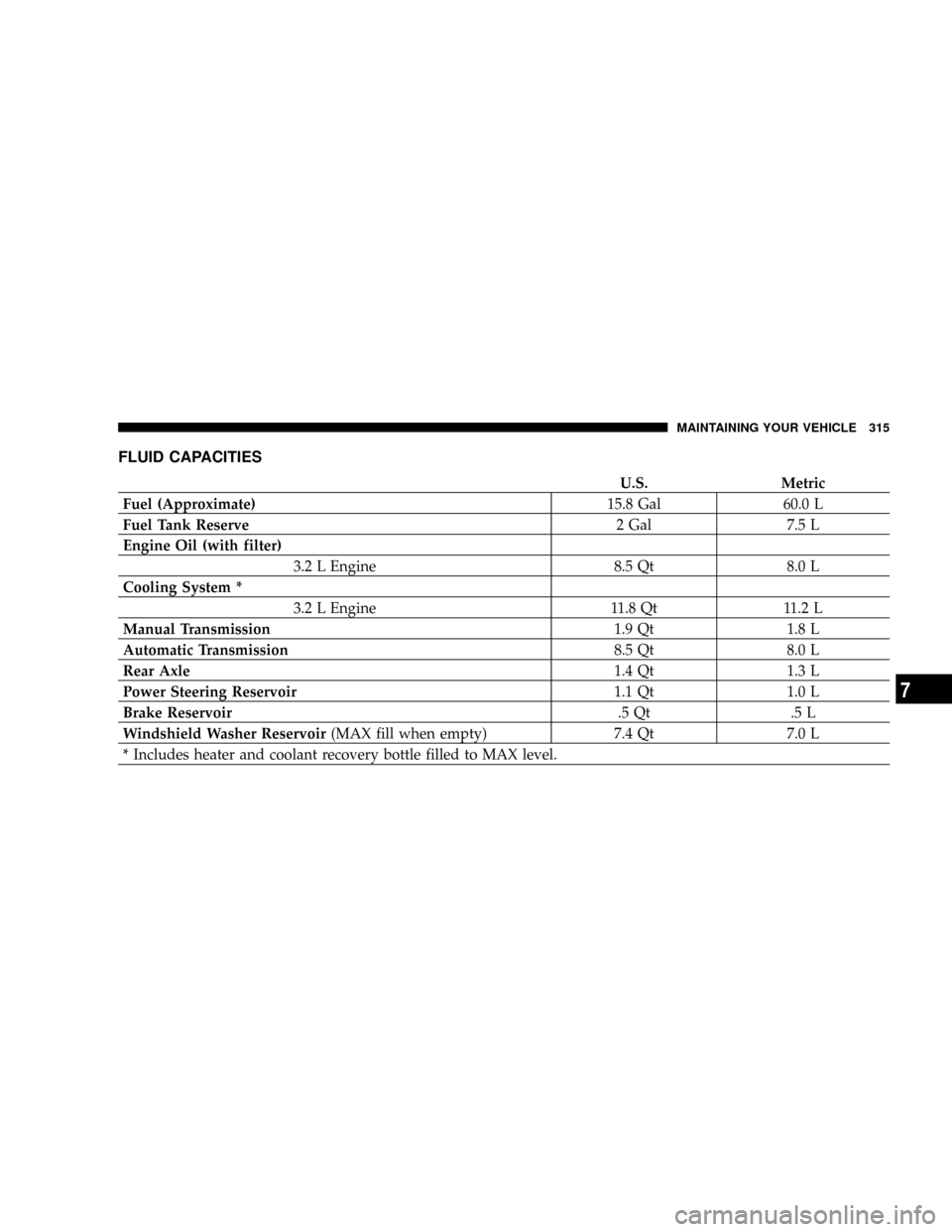
FLUID CAPACITIES
U.S. Metric
Fuel (Approximate)15.8 Gal 60.0 L
Fuel Tank Reserve2 Gal 7.5 L
Engine Oil (with filter)
3.2 L Engine 8.5 Qt 8.0 L
Cooling System *
3.2 L Engine 11.8 Qt 11.2 L
Manual Transmission1.9 Qt 1.8 L
Automatic Transmission8.5 Qt 8.0 L
Rear Axle1.4 Qt 1.3 L
Power Steering Reservoir1.1 Qt 1.0 L
Brake Reservoir.5 Qt .5 L
Windshield Washer Reservoir(MAX fill when empty) 7.4 Qt 7.0 L
* Includes heater and coolant recovery bottle filled to MAX level.
MAINTAINING YOUR VEHICLE 315
7
Page 318 of 358
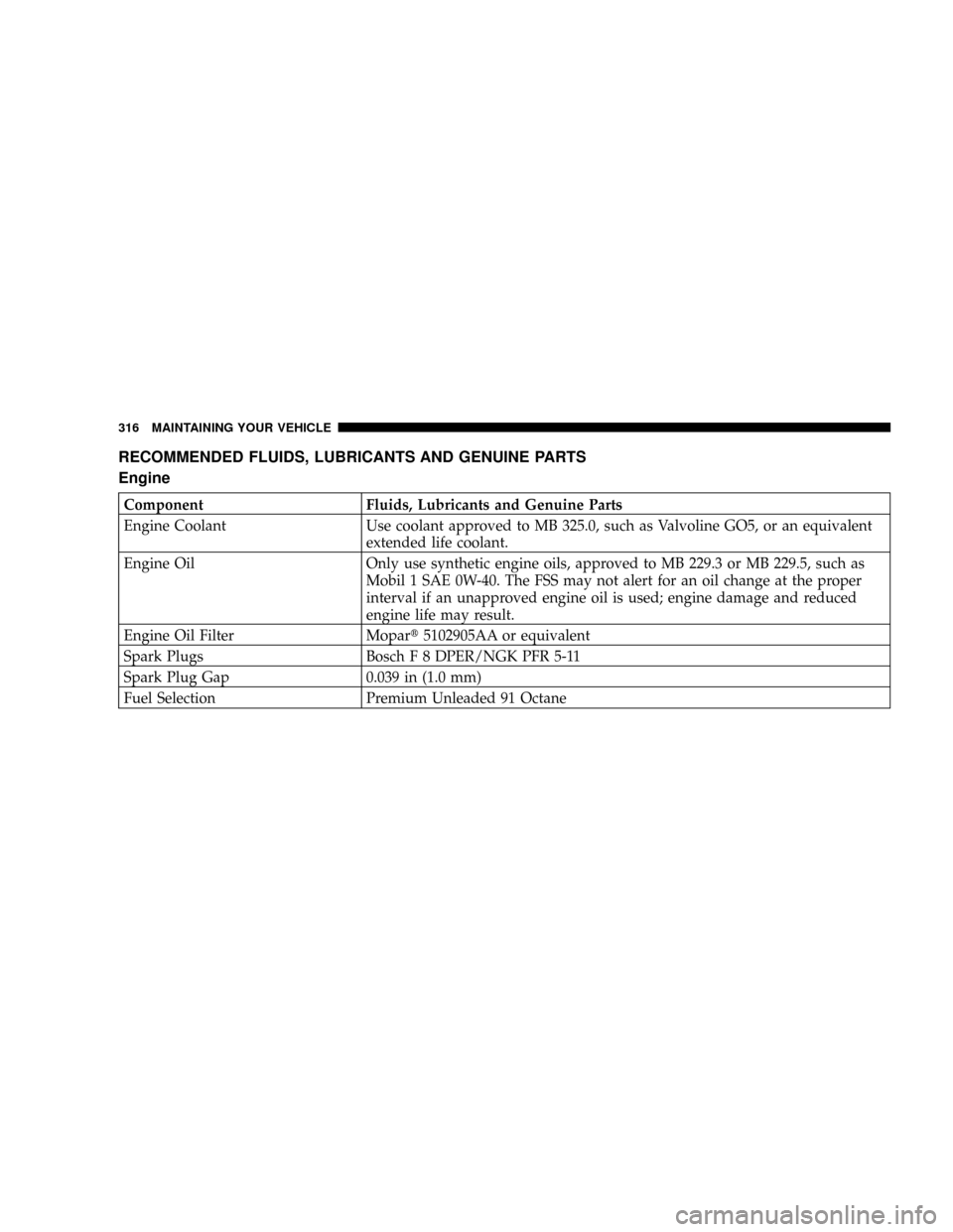
RECOMMENDED FLUIDS, LUBRICANTS AND GENUINE PARTS
Engine
Component Fluids, Lubricants and Genuine Parts
Engine Coolant Use coolant approved to MB 325.0, such as Valvoline GO5, or an equivalent
extended life coolant.
Engine Oil Only use synthetic engine oils, approved to MB 229.3 or MB 229.5, such as
Mobil 1 SAE 0W-40. The FSS may not alert for an oil change at the proper
interval if an unapproved engine oil is used; engine damage and reduced
engine life may result.
Engine Oil Filter Mopart5102905AA or equivalent
Spark Plugs Bosch F 8 DPER/NGK PFR 5-11
Spark Plug Gap 0.039 in (1.0 mm)
Fuel Selection Premium Unleaded 91 Octane
316 MAINTAINING YOUR VEHICLE
Page 319 of 358
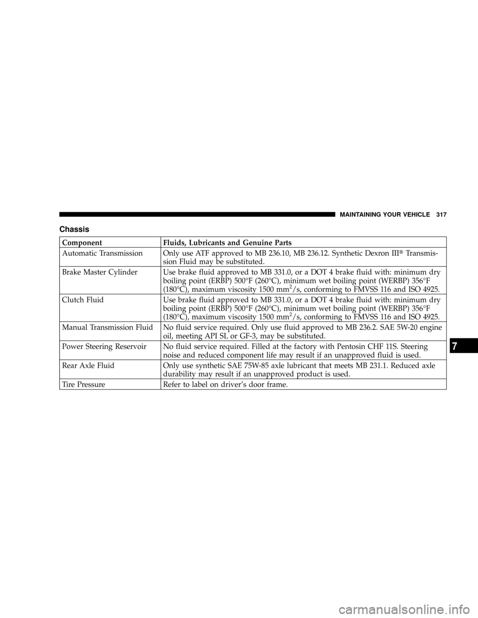
Chassis
Component Fluids, Lubricants and Genuine Parts
Automatic Transmission Only use ATF approved to MB 236.10, MB 236.12. Synthetic Dexron IIItTransmis-
sion Fluid may be substituted.
Brake Master Cylinder Use brake fluid approved to MB 331.0, or a DOT 4 brake fluid with: minimum dry
boiling point (ERBP) 500ÉF (260ÉC), minimum wet boiling point (WERBP) 356ÉF
(180ÉC), maximum viscosity 1500 mm
2/s, conforming to FMVSS 116 and ISO 4925.
Clutch Fluid Use brake fluid approved to MB 331.0, or a DOT 4 brake fluid with: minimum dry
boiling point (ERBP) 500ÉF (260ÉC), minimum wet boiling point (WERBP) 356ÉF
(180ÉC), maximum viscosity 1500 mm
2/s, conforming to FMVSS 116 and ISO 4925.
Manual Transmission Fluid No fluid service required. Only use fluid approved to MB 236.2. SAE 5W-20 engine
oil, meeting API SL or GF-3, may be substituted.
Power Steering Reservoir No fluid service required. Filled at the factory with Pentosin CHF 11S. Steering
noise and reduced component life may result if an unapproved fluid is used.
Rear Axle Fluid Only use synthetic SAE 75W-85 axle lubricant that meets MB 231.1. Reduced axle
durability may result if an unapproved product is used.
Tire Pressure Refer to label on driver's door frame.
MAINTAINING YOUR VEHICLE 317
7
Page 321 of 358
MAINTENANCE SCHEDULES
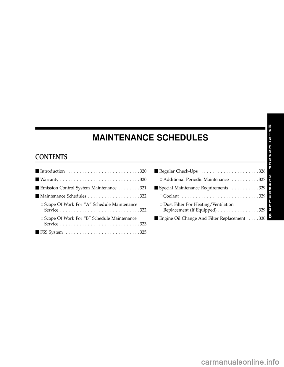
CONTENTS
mIntroduction..........................320
mWarranty.............................320
mEmission Control System Maintenance........321
mMaintenance Schedules...................322
NScope Of Work For ªAº Schedule Maintenance
Service.............................322
NScope Of Work For ªBº Schedule Maintenance
Service.............................323
mFSS System...........................325mRegular Check-Ups.....................326
NAdditional Periodic Maintenance..........327
mSpecial Maintenance Requirements..........329
NCoolant............................329
NDust Filter For Heating/Ventilation
Replacement (If Equipped)...............329
mEngine Oil Change And Filter Replacement....330
8
M
A
I
N
T
E
N
A
N
C
E
S
C
H
E
D
U
L
E
S
Page 323 of 358
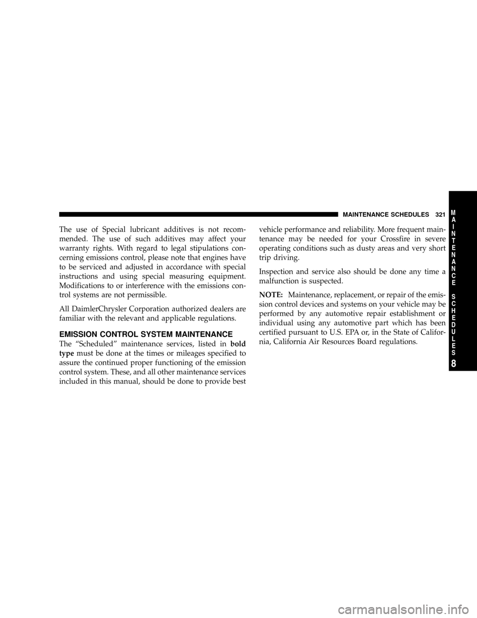
The use of Special lubricant additives is not recom-
mended. The use of such additives may affect your
warranty rights. With regard to legal stipulations con-
cerning emissions control, please note that engines have
to be serviced and adjusted in accordance with special
instructions and using special measuring equipment.
Modifications to or interference with the emissions con-
trol systems are not permissible.
All DaimlerChrysler Corporation authorized dealers are
familiar with the relevant and applicable regulations.
EMISSION CONTROL SYSTEM MAINTENANCE
The ªScheduledº maintenance services, listed inbold
typemust be done at the times or mileages specified to
assure the continued proper functioning of the emission
control system. These, and all other maintenance services
included in this manual, should be done to provide bestvehicle performance and reliability. More frequent main-
tenance may be needed for your Crossfire in severe
operating conditions such as dusty areas and very short
trip driving.
Inspection and service also should be done any time a
malfunction is suspected.
NOTE:Maintenance, replacement, or repair of the emis-
sion control devices and systems on your vehicle may be
performed by any automotive repair establishment or
individual using any automotive part which has been
certified pursuant to U.S. EPA or, in the State of Califor-
nia, California Air Resources Board regulations.
MAINTENANCE SCHEDULES 321
8
M
A
I
N
T
E
N
A
N
C
E
S
C
H
E
D
U
L
E
S
Page 325 of 358
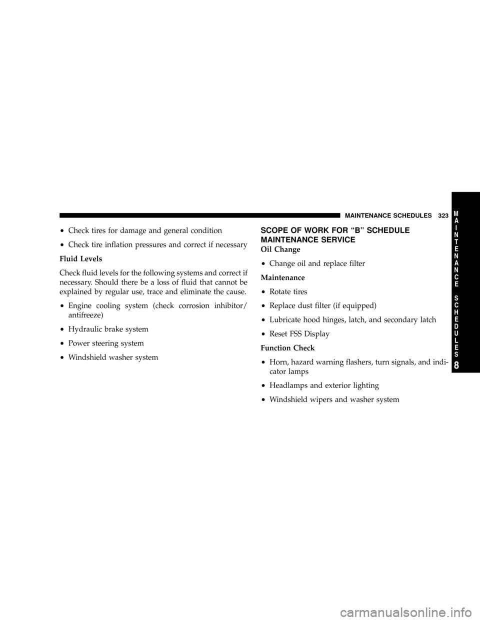
²Check tires for damage and general condition
²Check tire inflation pressures and correct if necessary
Fluid Levels
Check fluid levels for the following systems and correct if
necessary. Should there be a loss of fluid that cannot be
explained by regular use, trace and eliminate the cause.
²Engine cooling system (check corrosion inhibitor/
antifreeze)
²Hydraulic brake system
²Power steering system
²Windshield washer system
SCOPE OF WORK FOR ªBº SCHEDULE
MAINTENANCE SERVICE
Oil Change
²Change oil and replace filter
Maintenance
²Rotate tires
²Replace dust filter (if equipped)
²Lubricate hood hinges, latch, and secondary latch
²Reset FSS Display
Function Check
²Horn, hazard warning flashers, turn signals, and indi-
cator lamps
²Headlamps and exterior lighting
²Windshield wipers and washer system
MAINTENANCE SCHEDULES 323
8
M
A
I
N
T
E
N
A
N
C
E
S
C
H
E
D
U
L
E
S
Page 326 of 358
²Check seat belts for damage and proper function
²Test hydraulic brakes and check parking brake func-
tion
Inspection
²Check front and rear brake pads for lining thickness
²Check condition of front and rear brake discs
²Check tires for damage and general condition
²Check tire inflation pressures and correct if necessary
²Check major underbody components for leakage or
damage (if there are signs of leakage, determine cause
and repair)
²Check condition of front axle ball joints and rubber
boots
²Check condition of steering components and rubber
boots
²Check underhood components for leakage or damage
(if there are signs of leakage determine cause and
repair)
²Check condition of accessory drive belt
²Check headlamp aiming, adjust if necessary
²Check windshield wiper blades, replace if necessary
Fluid Levels
Check fluid levels for the following systems and correct if
necessary. Should there be a loss of fluid that cannot be
explained by regular use, trace and eliminate the cause.
²Engine cooling system (check corrosion inhibitor/
antifreeze)
²Hydraulic brake system
²Power steering system
²Windshield washer system
324 MAINTENANCE SCHEDULES
8
M
A
I
N
T
E
N
A
N
C
E
S
C
H
E
D
U
L
E
S
Page 327 of 358
FSS SYSTEM
The Flexible Service System (FSS) permits a flexible
service schedule that is directly related to the operating
conditions of the vehicle. See the Understanding Your
Instrument Panel section for details on how to use the
FSS.
The oil change interval for your vehicle is initially set at
7,000 mi (Canada: 11 000 km). Very light duty driving
cycles (most trips more than 10 mi [16 km]) at moderate
speeds in moderate temperature conditions) can extend
the service interval beyond 7,000 mi (Canada: 11 000 km).
IfANYof the following apply to your driving, the oil
change interval can be reduced significantly:
þDay or night temperatures are below 32ÉF (0ÉC).
þStop and go driving.
þExtensive engine idling.
þDriving in dusty conditions.
þShort trips of less than 10 mi (16 km).
þMore than 50% of your driving is at sustained high
speeds during hot weather, above 90ÉF (32ÉC).
There are two symbols which will appear in the main
odometer display field prior to the next suggested ser-
vice.
This symbol represents Service A.
This second symbol represents Service B. Ser-
vice B rotates with Service A and includes
additional service tasks.
The next service is normally calculated and
displayed next to the Service A or Service B
symbol as distance remaining before the next
service is required.
MAINTENANCE SCHEDULES 325
8
M
A
I
N
T
E
N
A
N
C
E
S
C
H
E
D
U
L
E
S