stop CHRYSLER PACIFICA 2004 1.G User Guide
[x] Cancel search | Manufacturer: CHRYSLER, Model Year: 2004, Model line: PACIFICA, Model: CHRYSLER PACIFICA 2004 1.GPages: 361, PDF Size: 5.21 MB
Page 100 of 361
²The pedalscannotbe adjusted when the vehicle is in R
(Reverse) or when the Speed Control is ON. A message
will be displayed in the Electronic Vehicle Information
Center (EVIC) if the pedals are attempted to be ad-
justed when the system is locked out (ªAdjustable
Pedal Disabled Ð Cruise Control Engagedº or ªAd-
justable Pedal Disabled Ð Vehicle In Reverseº).
NOTE:If your vehicle is equipped with memory seat
feature, your remote keyless entry transmitter or memory
seat buttons on the driver's door panel can be used to
recall the adjustable pedals to saved positions.CAUTION!
Do not place any article under the adjustable pedals
or impede its ability to move as it may cause damage
to the pedal controls. Pedal travel may become
limited if movement is stopped by an obstruction in
the adjustable pedal's path.
TO OPEN AND CLOSE THE HOOD
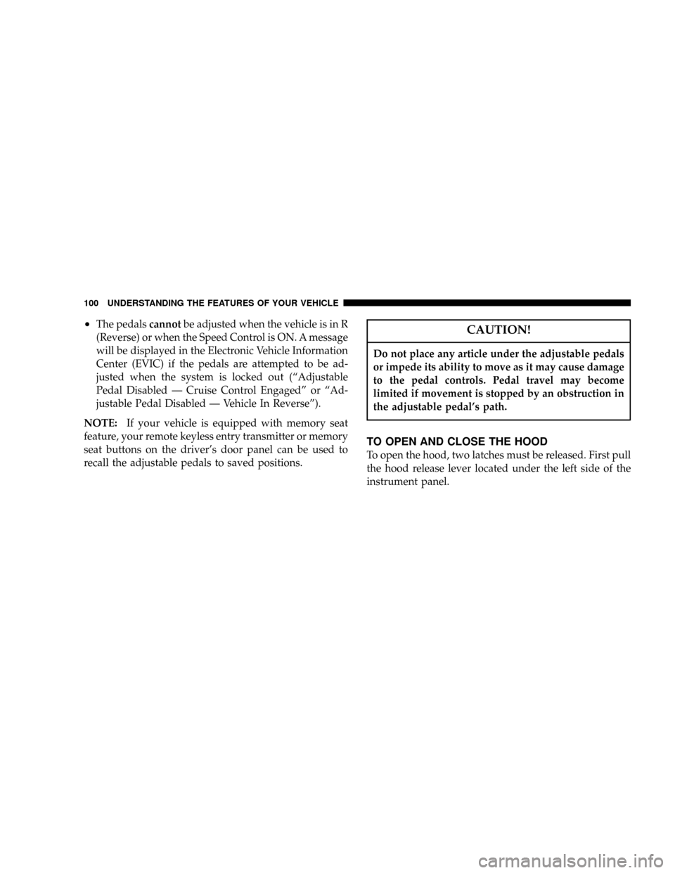
To open the hood, two latches must be released. First pull
the hood release lever located under the left side of the
instrument panel.
100 UNDERSTANDING THE FEATURES OF YOUR VEHICLE
Page 110 of 361
TILT STEERING COLUMN
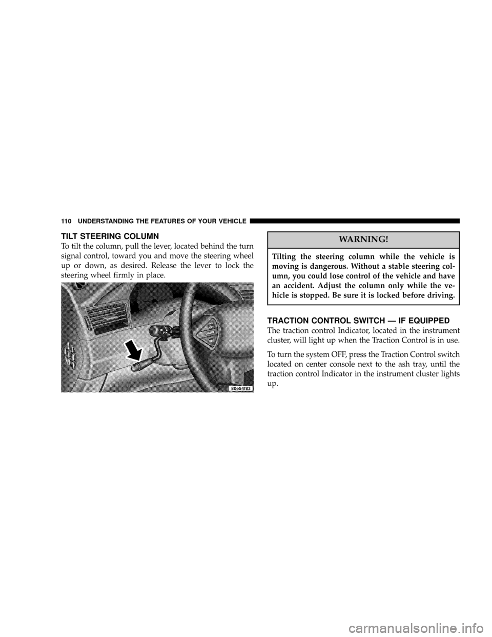
To tilt the column, pull the lever, located behind the turn
signal control, toward you and move the steering wheel
up or down, as desired. Release the lever to lock the
steering wheel firmly in place.WARNING!
Tilting the steering column while the vehicle is
moving is dangerous. Without a stable steering col-
umn, you could lose control of the vehicle and have
an accident. Adjust the column only while the ve-
hicle is stopped. Be sure it is locked before driving.
TRACTION CONTROL SWITCH Ð IF EQUIPPED
The traction control Indicator, located in the instrument
cluster, will light up when the Traction Control is in use.
To turn the system OFF, press the Traction Control switch
located on center console next to the ash tray, until the
traction control Indicator in the instrument cluster lights
up.
110 UNDERSTANDING THE FEATURES OF YOUR VEHICLE
Page 115 of 361
The lights also turn on when a front door, a rear door or
the liftgate is opened. The lights will also turn on when
the unlock button on the remote keyless entry transmitter
is pressed.
Sunglasses Storage
At the rear of the console a compartment is provided for
the storage of a pair of sunglasses.
Press the door latch to open the compartment. The door
will slowly rotate to an open position.
GARAGE DOOR OPENER Ð IF EQUIPPED
The HomeLinktUniversal Transceiver replaces up to
three remote controls (hand held transmitters) that oper-
ate devices such as garage door openers, motorized
gates, or home lighting. It triggers these devices at the
push of a button. The Universal Transceiver operates off
your vehicle's battery and charging system; no batteries
are needed.For additional information on HomeLinkt, call 1±800±
355±3515, or on the internet at www.homelink.com.
WARNING!
A moving garage door can cause injury to people and
pets in the path of the door. People or pets could be
seriously or fatally injured. Only use this transceiver
with a garage door opener that has a ªstop and
reverseº feature as required by federal safety stan-
dards. This includes most garage door opener mod-
els manufactured after 1982. Do not use a garage
door opener without these safety features it could
cause injury or death. Call toll-free 1±800±355±3515
or, on the Internet at www.homelink.com for safety
information or assistance.
UNDERSTANDING THE FEATURES OF YOUR VEHICLE 115
3
Page 121 of 361

POWER SUNROOF Ð IF EQUIPPED
The power sunroof switches are located between the sun
visors on the overhead console.Press and hold the switch rearward to fully open the
sunroof. The sunroof can be stopped at any position
between closed and full open. Momentarily pressing the
switch rearward will activate the Express Open Feature,
causing the sunroof to open automatically.
Press and hold the button in the center of the sunroof
switch to open the vent. The sunroof can be stopped at
any position between closed and full vent. To close the
sunroof from the vent position, press and hold the switch
forward. Releasing the switch will stop the movement of
the sunroof and the sunroof will remain in the partial
vent position until the switch is pushed forward again.
NOTE:The power sunroof switches remain active for
up to 45 seconds after the ignition switch has been turned
off. Opening either front door will cancel this feature.
UNDERSTANDING THE FEATURES OF YOUR VEHICLE 121
3
Page 122 of 361

Express Open Feature
The sunroof is equipped with an intermediate stop or
comfort stop position. This feature is designed to elimi-
nate wind buffeting at vehicle speeds between 20-40 mph
(32-64 km/h). To operate this feature, momentarily press
the switch rearward to activate the Express Open Feature
and the glass will automatically stop at the comfort stop
position. Pressing the switch rearward again will fully
open the sunroof.During the Express Open operation, any movement of
the switch will stop the sunroof and it will remain in a
partial open position. Again, momentarily pressing the
switch rearward will activate the Express Open Feature.
To close the sunroof, hold the switch in the forward
position. Again, any release of the switch will stop the
movement and the sunroof will remain in a partial open
condition until the switch is pushed forward again.
The sunshade can be opened manually. It will also open
as the sunroof opens. The sunshade cannot be closed if
the sunroof is open.
122 UNDERSTANDING THE FEATURES OF YOUR VEHICLE
Page 128 of 361
WARNING!
In an accident a cargo cover loose in the vehicle
could cause injury. It could fly around in a sudden
stop and strike someone in the vehicle. Do not store
the cargo cover on the cargo floor or in the passenger
compartment. Remove the cover from the vehicle
when taken from its mounting. Do not store in the
vehicle.
Stowed Position
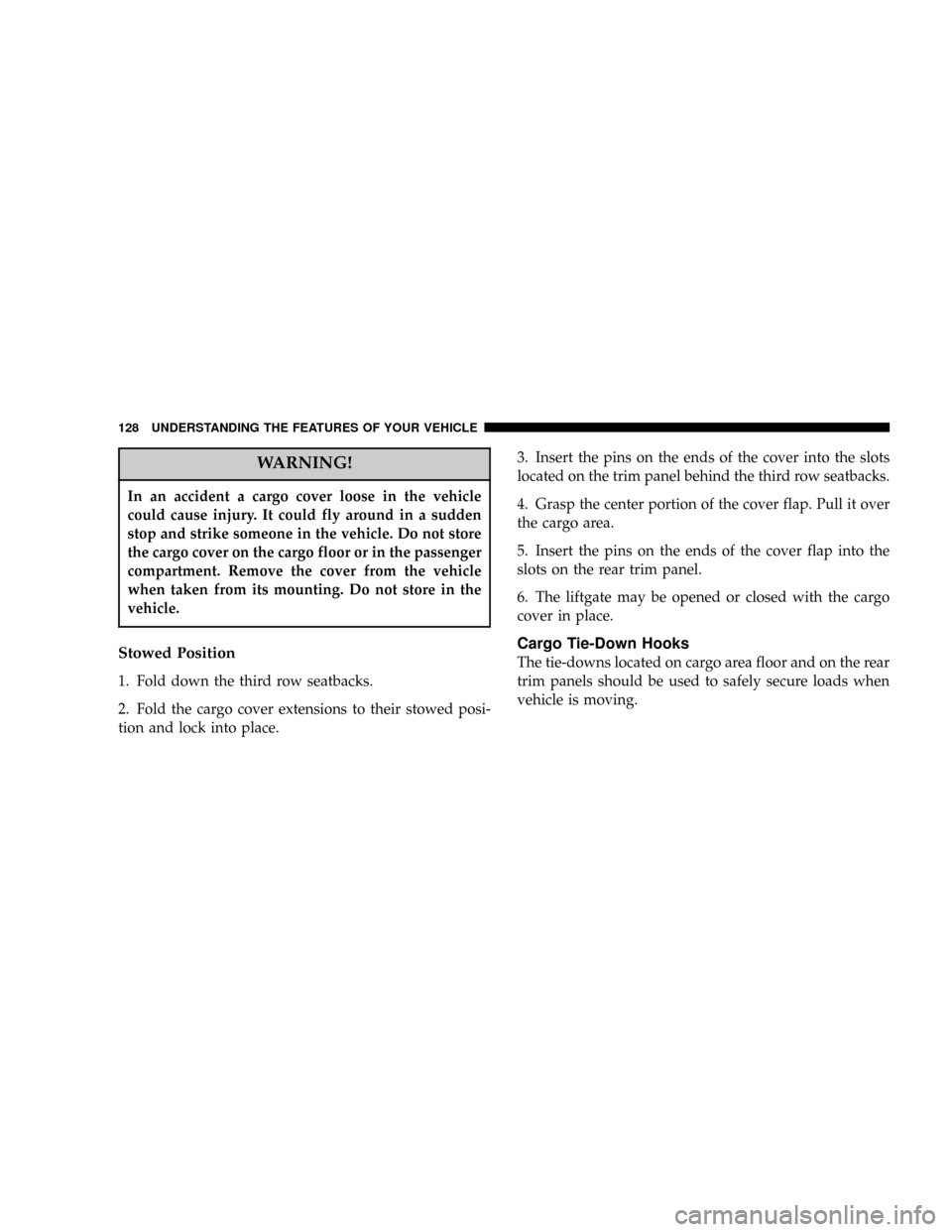
1. Fold down the third row seatbacks.
2. Fold the cargo cover extensions to their stowed posi-
tion and lock into place.3. Insert the pins on the ends of the cover into the slots
located on the trim panel behind the third row seatbacks.
4. Grasp the center portion of the cover flap. Pull it over
the cargo area.
5. Insert the pins on the ends of the cover flap into the
slots on the rear trim panel.
6. The liftgate may be opened or closed with the cargo
cover in place.
Cargo Tie-Down Hooks
The tie-downs located on cargo area floor and on the rear
trim panels should be used to safely secure loads when
vehicle is moving.
128 UNDERSTANDING THE FEATURES OF YOUR VEHICLE
Page 129 of 361
WARNING!
²Cargo tie-down hooks are not safe anchors for a
child seat tether strap. In a sudden stop or colli-
sion a hook could pull loose and allow the child
seat to come loose. A child could be badly injured.
Use only the anchors provided for child seat
tethers.
²The weight and position of cargo and passengers
can change the vehicle center of gravity and
vehicle handling. To avoid loss of control result-
ing in personal injury, follow these guidelines for
loading your vehicle:
²Always place cargo evenly on the cargo floor. Put
heavier objects as low and as far forward as possible.
²Place as much cargo as possible in front of the rear
axle. Too much weight or improperly placed weight
over or behind the rear axle can cause the rear of the
vehicle to sway.
²Do not pile luggage or cargo higher than the top of the
seatback. This could impair visibility or become a
dangerous projectile in a sudden stop or collision.
WARNING!
To help protect against personal injury, passengers
should not be seated in the rear cargo area. The rear
cargo space is intended for load carrying purposes
only, not for passengers, who should sit in seats and
use seat belts.
UNDERSTANDING THE FEATURES OF YOUR VEHICLE 129
3
Page 138 of 361

INSTRUMENT CLUSTER DESCRIPTIONS
1. Voltage Light
This light monitors the electrical system voltage.
The light should turn on momentarily as the
engine is started. If the light stays on or turns on while
driving, it indicates a problem with the charging system.
Immediate service should be obtained.
2. Temperature Gauge
The temperature gauge shows engine coolant tempera-
ture. Any reading within the normal range indicates that
the engine cooling system is operating satisfactorily.
The gauge pointer will likely indicate a higher tempera-
ture when driving in hot weather, up mountain grades,
or when towing a trailer. It should not be allowed to
exceed the upper limits of the normal operating range.
CAUTION!
Driving with a hot engine cooling system could
damage your vehicle. If temperature gauge reads (H),
pull over and stop the vehicle. Idle the vehicle with
the air conditioner turned off until the pointer drops
back into the normal range. If the pointer remains on
the ªHº, and you hear continuous chimes, turn the
engine off immediately, and call for service.
138 UNDERSTANDING YOUR INSTRUMENT PANEL
Page 140 of 361
is not functioning and that service is required. However,
the conventional brake system will continue to operate
normally if the BRAKE warning light is not on.
If the ABS light is on, the brake system should be serviced
as soon as possible to restore the benefits of Anti-Lock
brakes. If the ABS light does not turn on when the
Ignition switch is turned to the ON position, have the
light inspected by an authorized dealer.
7. Brake System Warning Light
This light monitors various brake functions,
including brake fluid level and parking brake
application. If the brake light turns on, it may
indicate that the parking brake is applied, there
is a low brake fluid level or there is a problem with the
anit-lock brake system.
The dual brake system provides a reserve braking capac-
ity in the event of a failure to a portion of the hydraulic
system. Failure of either half of the dual brake system isindicated by the Brake Warning Light which will turn on
when the brake fluid level in the master cylinder has
dropped below a specified level.
The light will remain on until the cause is corrected.
NOTE:The light may flash momentarily during sharp
cornering maneuvers which change fluid level condi-
tions. The vehicle should have service performed.
If brake failure is indicated, immediate repair is neces-
sary.
WARNING!
Driving a vehicle with the brake light on is danger-
ous. Part of the brake system may have failed. It will
take longer to stop the vehicle. You could have an
accident. Have the vehicle checked immediately.
140 UNDERSTANDING YOUR INSTRUMENT PANEL
Page 144 of 361
19. Oil Pressure Warning Light
This light shows low engine oil pressure. The light
should turn on momentarily when the engine is
started. If the light turns on while driving, stop the
vehicle and shut off the engine as soon as possible. A
continuous chime will sound when this light turns on.
Do not operate the vehicle until the cause is corrected.
This light does not show how much oil is in the engine.
The engine oil level must be checked under the hood.
20. Seat Belt Reminder Light
When the ignition switch is first turned ON, this
light will turn on for 5 to 8 seconds as a bulb check.
During the bulb check, if the driver's seat belt is
unbuckled, a chime will sound. After the bulb check or
when driving, if the driver seat belt remains unbuckled,
the Seat Belt Warning Light will flash or remain oncontinuously. Refer to9Enhanced Driver Seat Belt Re-
minder System (BeltAlertŸ)9in the Occupant Restraints
section for more information.
21. Tire Pressure Monitor Warning Light Ð If
Equipped
This light will turn on when there is a Low tire
pressure condition. The light will also turn on
if a problem exist with any tire sensor. The light
will remain on until the tire pressure is prop-
erly set or the problem with the sensor is corrected.
This light will turn on momentarily as a bulb check when
the engine is started.
When the tire pressure monitoring system warning light
is lit, one or more of your tires is significantly underin-
flated. You should stop and check your tires as soon as
possible, and inflate them to the proper pressure as
indicated on the tire and loading information placard.
Driving on a significantly underinflated tire causes the
144 UNDERSTANDING YOUR INSTRUMENT PANEL