ECO CHRYSLER PACIFICA 2017 2.G Owners Manual
[x] Cancel search | Manufacturer: CHRYSLER, Model Year: 2017, Model line: PACIFICA, Model: CHRYSLER PACIFICA 2017 2.GPages: 828, PDF Size: 7.58 MB
Page 535 of 828
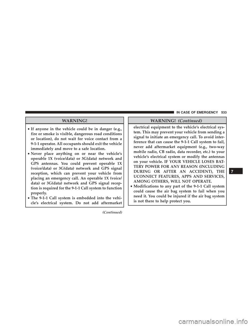
WARNING!
•If anyone in the vehicle could be in danger (e.g.,
fire or smoke is visible, dangerous road conditions
or location), do not wait for voice contact from a
9-1-1 operator. All occupants should exit the vehicle
immediately and move to a safe location.
• Never place anything on or near the vehicle’s
operable 1X (voice/data) or 3G(data) network and
GPS antennas. You could prevent operable 1X
(voice/data) or 3G(data) network and GPS signal
reception, which can prevent your vehicle from
placing an emergency call. An operable 1X (voice/
data) or 3G(data) network and GPS signal recep-
tion is required for the 9-1-1 Call system to function
properly.
• The 9-1-1 Call system is embedded into the vehi-
cle’s electrical system. Do not add aftermarket
(Continued)
WARNING! (Continued)
electrical equipment to the vehicle’s electrical sys-
tem. This may prevent your vehicle from sending a
signal to initiate an emergency call. To avoid inter-
ference that can cause the 9-1-1 Call system to fail,
never add aftermarket equipment (e.g., two-way
mobile radio, CB radio, data recorder, etc.) to your
vehicle’s electrical system or modify the antennas
on your vehicle. IF YOUR VEHICLE LOSES BAT-
TERY POWER FOR ANY REASON (INCLUDING
DURING OR AFTER AN ACCIDENT), THE
UCONNECT FEATURES, APPS AND SERVICES,
AMONG OTHERS, WILL NOT OPERATE.
• Modifications to any part of the 9-1-1 Call system
could cause the air bag system to fail when you
need it. You could be injured if the air bag system
is not there to help protect you.
7
IN CASE OF EMERGENCY 533
Page 537 of 828
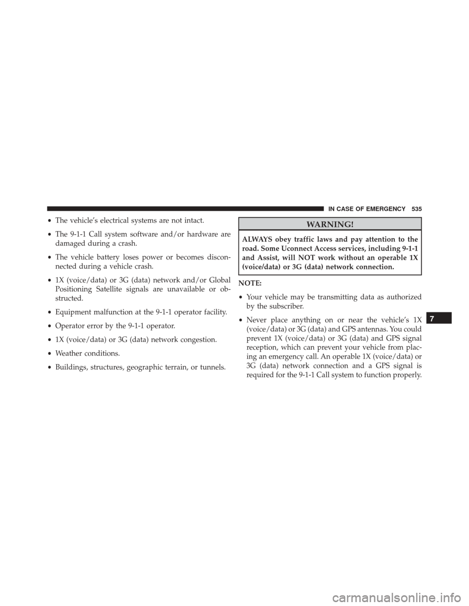
•The vehicle’s electrical systems are not intact.
• The 9-1-1 Call system software and/or hardware are
damaged during a crash.
• The vehicle battery loses power or becomes discon-
nected during a vehicle crash.
• 1X (voice/data) or 3G (data) network and/or Global
Positioning Satellite signals are unavailable or ob-
structed.
• Equipment malfunction at the 9-1-1 operator facility.
• Operator error by the 9-1-1 operator.
• 1X (voice/data) or 3G (data) network congestion.
• Weather conditions.
• Buildings, structures, geographic terrain, or tunnels.WARNING!
ALWAYS obey traffic laws and pay attention to the
road. Some Uconnect Access services, including 9-1-1
and Assist, will NOT work without an operable 1X
(voice/data) or 3G (data) network connection.
NOTE:
• Your vehicle may be transmitting data as authorized
by the subscriber.
• Never place anything on or near the vehicle’s 1X
(voice/data) or 3G (data) and GPS antennas. You could
prevent 1X (voice/data) or 3G (data) and GPS signal
reception, which can prevent your vehicle from plac-
ing an emergency call. An operable 1X (voice/data) or
3G (data) network connection and a GPS signal is
required for the 9-1-1 Call system to function properly.
7
IN CASE OF EMERGENCY 535
Page 541 of 828
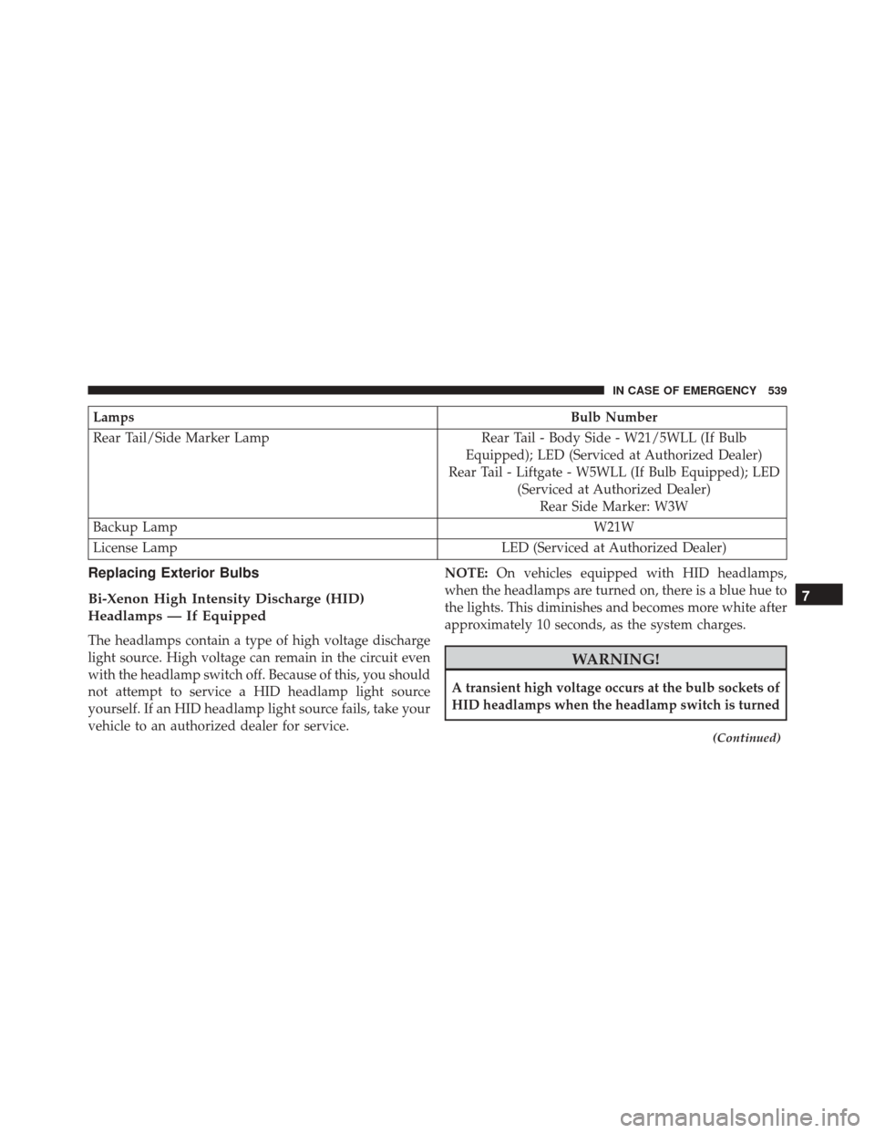
LampsBulb Number
Rear Tail/Side Marker Lamp Rear Tail - Body Side - W21/5WLL (If Bulb
Equipped); LED (Serviced at Authorized Dealer)
Rear Tail - Liftgate - W5WLL (If Bulb Equipped); LED (Serviced at Authorized Dealer)Rear Side Marker: W3W
Backup Lamp W21W
License Lamp LED (Serviced at Authorized Dealer)
Replacing Exterior Bulbs
Bi-Xenon High Intensity Discharge (HID)
Headlamps — If Equipped
The headlamps contain a type of high voltage discharge
light source. High voltage can remain in the circuit even
with the headlamp switch off. Because of this, you should
not attempt to service a HID headlamp light source
yourself. If an HID headlamp light source fails, take your
vehicle to an authorized dealer for service.NOTE:
On vehicles equipped with HID headlamps,
when the headlamps are turned on, there is a blue hue to
the lights. This diminishes and becomes more white after
approximately 10 seconds, as the system charges.
WARNING!
A transient high voltage occurs at the bulb sockets of
HID headlamps when the headlamp switch is turned
(Continued)
7
IN CASE OF EMERGENCY 539
Page 554 of 828
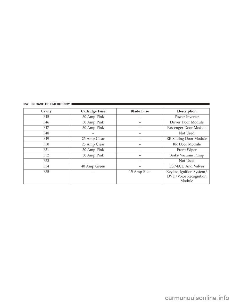
CavityCartridge Fuse Blade FuseDescription
F45 30 Amp Pink –Power Inverter
F46 30 Amp Pink –Driver Door Module
F47 30 Amp Pink –Passenger Door Module
F48 ––Not Used
F49 25 Amp Clear –RR Sliding Door Module
F50 25 Amp Clear –RR Door Module
F51 30 Amp Pink –Front Wiper
F52 30 Amp Pink –Brake Vacuum Pump
F53 ––Not Used
F54 40 Amp Green –ESP-ECU And Valves
F55 –15 Amp Blue Keyless Ignition System/
DVD/Voice RecognitionModule
552 IN CASE OF EMERGENCY
Page 570 of 828
CAUTION!(Continued)
damaged if the inflatable spare tire is mounted
incorrectly.
WARNING!
To avoid the risk of forcing the vehicle off the jack,
do not tighten the wheel nuts fully until the vehicle
has been lowered. Failure to follow this warning may
result in serious injury.
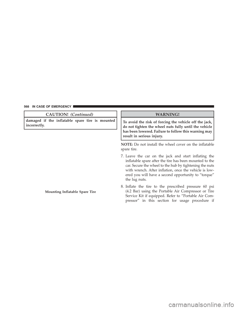
NOTE: Do not install the wheel cover on the inflatable
spare tire.
7. Leave the car on the jack and start inflating the inflatable spare after the tire has been mounted to the
car. Secure the wheel to the hub by tightening the nuts
with wrench. After inflation, once the vehicle is low-
ered you will have a second opportunity to “torque”
the lug nuts.
8. Inflate the tire to the prescribed pressure 60 psi (4.2 Bar) using the Portable Air Compressor or Tire
Service Kit if equipped. Refer to “Portable Air Com-
pressor” in this section for usage procedure if
Mounting Inflatable Spare Tire
568 IN CASE OF EMERGENCY
Page 575 of 828
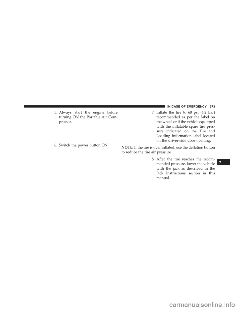
5. Always start the engine beforeturning ON the Portable Air Com-
pressor.
6. Switch the power button ON. 7. Inflate the tire to 60 psi (4.2 Bar)
recommended as per the label on
the wheel or if the vehicle equipped
with the inflatable spare tire pres-
sure indicated on the Tire and
Loading information label located
on the driver-side door opening.
NOTE: If the tire is over inflated, use the deflation button
to reduce the tire air pressure.
8. After the tire reaches the recom-mended pressure, lower the vehicle
with the jack as described in the
Jack Instructions section in this
manual.
7
IN CASE OF EMERGENCY 573
Page 578 of 828
Using The Power ButtonPush and release the Power Button
once to turn On the Tire Service Kit.
Push and release the Power Button
again to turn Off the Tire Service Kit.
Using The Deflation Button Push the Deflation Button to reduce
the air pressure in the tire if it becomes
over-inflated.WARNING!
•Keep Tire Service Kit away from open flames or
heat source.
• A loose Tire Service Kit thrown forward in a
collision or hard stop could endanger the occupants
of the vehicle. Always stow the Tire Service Kit in
the place provided. Failure to follow these warn-
ings can result in injuries that are serious or fatal to
you, your passengers, and others around you.
• Take care not to allow the contents of Tire Service
Kit to come in contact with hair, eyes, or clothing.
Tire Service Kit sealant is harmful if inhaled,
swallowed, or absorbed through the skin. It causes
skin, eye, and respiratory irritation. Flush immedi-
ately with plenty of water if there is any contact
with eyes or skin. Change clothing as soon as
possible, if there is any contact with clothing.
(Continued)
576 IN CASE OF EMERGENCY
Page 581 of 828
9. Inflate the tire to 60 psi (4.2 Bar)recommended as per the label on
the wheel or if the vehicle equipped
with the inflatable spare tire pres-
sure indicated on the Tire and
Loading information label located
on the driver-side door opening.
NOTE: If the tire is over inflated, use the deflation button
to reduce the tire air pressure.
10. After the tire reaches the recom-mended pressure, lower the ve-
hicle with the jack as described in
the Jack Instructions section in this
manual. 11. Remove the speed limit label
sticker from the Tire Service Kit
and place it on the center of the
steering wheel.
12. Return the Tire Service Kit to the foam tray and secure it with the strap. Store the foam tray in the
cargo area.
Road Tire Installation
Vehicles Equipped With Wheel Covers
1. Mount the road tire on the axle.
2. To ease the installation process for steel wheels withwheel covers, install two lug nuts on the mounting
studs which are on each side of the valve stem. Install
7
IN CASE OF EMERGENCY 579
Page 586 of 828
Using The Mode Select Knob And Hoses
Your Tire Service Kit is equipped with the following
symbols to indicate the air or sealant mode.
Selecting Air ModePush in the Mode Select Knob and
turn to this position for air pump
operation only.
Selecting Sealant Mode Push in the Mode Select Knob and
turn to this position to inject the Tire
Service Kit Sealant and to inflate the
tire. Using The Power Button
Push and release the Power Button
once to turn On the Tire Service Kit.
Push and release the Power Button
again to turn Off the Tire Service Kit.
Using The Deflation Button Push the Deflation Button to reduce
the air pressure in the tire if it becomes
over-inflated.
Tire Service Kit Usage Precautions
• Replace the Tire Service Kit Sealant Bottle prior to the
expiration date (printed at the lower right hand corner
584 IN CASE OF EMERGENCY
Page 591 of 828
3. After pushing the Power Button,the sealant (white fluid) will flow
from the Sealant Bottle through the
Sealant Hose and into the tire.
NOTE: Sealant may leak out through the puncture in the
tire.
If the sealant (white fluid) does not flow within0–10
seconds through the Sealant Hose:
1. Push the Power Button to turn Off the Tire Service Kit. Disconnect the Sealant Hose from the valve stem. Make sure the valve stem is free of debris. Reconnect
the Sealant Hose to the valve stem. Check that the
Mode Select Knob is in the Sealant Mode position and
not Air Mode. Push the Power Button to turn On the
Tire Service Kit.
2. Connect the Power Plug to a different 12 Volt power outlet in your vehicle or another vehicle, if available.
Make sure the engine is running before turning ON
the Tire Service Kit.
3. The Sealant Bottle may be empty due to previous use. Call for assistance.
7
IN CASE OF EMERGENCY 589