engine oil CHRYSLER PACIFICA 2019 Owners Manual
[x] Cancel search | Manufacturer: CHRYSLER, Model Year: 2019, Model line: PACIFICA, Model: CHRYSLER PACIFICA 2019Pages: 718, PDF Size: 8.6 MB
Page 194 of 718
3. Speedometer•Indicates vehicle speed.
4. Fuel Gauge •The gauge shows the level of fuel in the fuel tank when
the ignition switch is in the ON/RUN position.
•
The fuel pump symbol points to the side of the
vehicle where the fuel door is located.
5. Temperature Gauge
•The temperature gauge shows engine coolant tem-
perature. Any reading within the normal range indi-
cates that the engine cooling system is operating
satisfactorily.
• The gauge can indicate a higher temperature when
driving in hot weather or up mountain grades. It
should not be allowed to exceed the upper limits of the
normal operating range.
WARNING!
Driving with a hot engine cooling system could dam-
age your vehicle. If the temperature gauge reaches “H”
pull over and stop the vehicle. Idle the vehicle with the
air conditioner turned off until the gauge drops back
(Continued)
WARNING! (Continued)
into the normal range and is no longer red. If the gauge
remains on the “H”, turn the engine off immediately
and call an authorized dealer for service.
WARNING!
A hot engine cooling system is dangerous. You or
others could be badly burned by steam or boiling
coolant. You may want to call an authorized dealer for
service if your vehicle overheats. If you decide to look
under the hood yourself, see “Servicing And Mainte-
nance”.
NOTE: The hard telltales will illuminate for a bulb check
when the ignition is first cycled.
INSTRUMENT CLUSTER DISPLAY
Your vehicle is equipped with an instrument cluster dis-
play, which offers useful information to the driver. With the
ignition in the STOP/OFF position (and the key removed,
for vehicles with mechanical key), opening/closing of a
door will activate the display for viewing, and display the
total miles or kilometers in the odometer. Your instrument
192 GETTING TO KNOW YOUR INSTRUMENT PANEL
Page 196 of 718
•Right Arrow Button
Push and release the rightarrow button to access
the information screens or submenu screens of a
main menu item.
• Back/Left Arrow Button
Push and release the leftarrow button to access
the information screens or submenu screens of a
main menu item.
• OK Button
Push the OKbutton to access/select the information
screens or submenu screens of a Main Menu item. Push
and hold the OKbutton for two seconds to reset
displayed/selected features that can be reset.
The instrument cluster display (base/premium cluster)
features a driver-interactive display that is located in the
center of the instrument cluster, and may include the
following menu/submenu items:
• Speedometer
• Vehicle Info
• Driver Assist — If Equipped •
Fuel Economy
• Trip (Trip A/Trip B)
• Stop/Start — If Equipped
• Audio
• Messages
• Screen Setup
Oil Life Reset
•Your vehicle is equipped with an engine oil change
indicator system. The “Oil Change Required” message
will display for approximately five seconds after a single
chime has sounded, to indicate the next scheduled oil
change interval. The engine oil change indicator system
is duty cycle based, which means the engine oil change
interval may fluctuate, dependent upon your personal
driving style.
• Unless reset, this message will continue to display each
time the ignition is cycled to the ON/RUN position.
• To reset the oil change indicator after performing the
scheduled maintenance, refer to the following proce-
dure.
194 GETTING TO KNOW YOUR INSTRUMENT PANEL
Page 197 of 718
Oil Life Reset
Without pressing the brake pedal, push the ENGINE
START/STOP button and place the ignition in the ON/
RUN position (do not start the vehicle.)
1. Push theOKbutton to enter the instrument cluster
display menu screen.
2. Push and release the downarrow button to access the
”Oil Life” menu screen.
3. Push the leftarrow button or right arrow button to
access the “Vehicle Info” submenu.
4. Hold the OKbutton to reset the “Oil Life” to 100%.
5. Push the uparrow button to exit the instrument cluster
display menu screen. Secondary Method For Oil Life Reset Procedure
1. Without pushing the brake pedal, place the ignition in
the ON/RUN position (do not start the engine).
2. Fully press the accelerator pedal, slowly, three times within ten seconds.
3. Without pushing the brake pedal, place the ignition in the OFF/LOCK position.
NOTE: If the indicator message illuminates when you
start the vehicle, the oil change indicator system did not
reset. If necessary, repeat this procedure.
4
GETTING TO KNOW YOUR INSTRUMENT PANEL 195
Page 200 of 718
Engine Hours — If Equipped
Displays the number of hours of engine operation.
Oil Life
To reset the Oil Life, you must hold the OK button. The
“Hold OK to Reset” instruction will be displayed at all
times, but the following conditions will need to be met in
order to reset Oil Life:
•The vehicle must be off
• The ignition must be in the ON/RUN position
If the conditions are met, holding the OKbutton will reset
the gauge and the numeric display will return to 100%.
If the conditions are not met, a popup message will display
for 5 seconds, describing the required conditions, and then
the Oil Life screen will reappear.
Driver Assist
Push and release the upordown arrow button until the
Driver Assist display icon is highlighted in the instrument
cluster display. Refer to “Adaptive Cruise Control (ACC)
— If Equipped” in “Starting And Operating” for further
information.
Fuel Economy
Push and release the upordown arrow button until the
Fuel Economy Menu item is highlighted in the instrument
cluster display. The Fuel Economy Menu will display the
following:
• Two sub menu pages that can be toggled between using
the left and right arrow buttons; one with Current Value
displayed and one without the Current Value displayed:
– Average Fuel Economy (MPG, L/100 km, or km/l)
– Range To Empty (miles or km)
– Current Fuel Economy (MPG, L/100 km, or km/l)
– The Max and Min values will correspond to the particular engine requirements
• Hold OKto reset average fuel economy information.
Trip Info
Push and release the upordown arrow button until the
Trip Menu item is highlighted in the instrument cluster
display. Push the leftorright arrow button to scroll
through the Trip A and Trip B submenus. The Trip infor-
mation will display the following:
• Distance
• Average Fuel Economy
198 GETTING TO KNOW YOUR INSTRUMENT PANEL
Page 210 of 718
— Hood Open Warning Light
This warning light will illuminate when the hood is left
open and not fully closed.
NOTE:If the vehicle is moving, there will also be a single
chime.
— Liftgate Open Warning Light
This warning light will illuminate when the liftgate is open.
NOTE: If the vehicle is moving, there will also be a single
chime.
— Seat Belt Reminder Warning Light
This warning light indicates when the driver or passenger
seat belt is unbuckled. When the ignition is first placed in
the ON/RUN or ACC/ON/RUN position and if the
driver ’s seat belt is unbuckled, a chime will sound and the
light will turn on. When driving, if the driver or front
passenger seat belt remains unbuckled, the Seat Belt Re-
minder Light will flash or remain on continuously and a
chime will sound.
Refer to “Occupant Restraint Systems” in “Safety” for
further information.
— Transmission Temperature Warning Light — If
Equipped
This warning light will illuminate to warn of a high
transmission fluid temperature. This may occur with
strenuous usage such as trailer towing. If this light turns
on, stop the vehicle and run the engine at idle or slightly
faster, with the transmission in PARK or NEUTRAL, until
the light turns off. Once the light turns off, you may
continue to drive normally.
WARNING!
If you continue operating the vehicle when the Trans-
mission Temperature Warning Light is illuminated you
could cause the fluid to boil over, come in contact with
hot engine or exhaust components and cause a fire.
CAUTION!
Continuous driving with the Transmission Tempera-
ture Warning Light illuminated will eventually cause
severe transmission damage or transmission failure.
208 GETTING TO KNOW YOUR INSTRUMENT PANEL
Page 211 of 718
— Vehicle Security Warning Light — If Equipped
This warning light will flash at a fast rate for approxi-
mately 15 seconds when the vehicle security alarm is
arming, and then will flash slowly until the vehicle is
disarmed.
— Oil Temperature Warning Light
This warning light will illuminate to indicate the engine oil
temperature is high. If the light turns on while driving,
stop the vehicle and shut off the engine as soon as possible.
Wait for oil temperature to return to normal levels.
— Oil Pressure Warning Light
This warning light will illuminate to indicate low engine
oil pressure. If the light turns on while driving, stop the
vehicle, shut off the engine as soon as possible, and contact
an authorized dealer. A chime will sound when this light
turns on.
Do not operate the vehicle until the cause is corrected. This
light does not indicate how much oil is in the engine. The
engine oil level must be checked under the hood.
Yellow Warning Lights
— Adaptive Cruise Control (ACC) Fault Warning
Light — If Equipped
This warning light will illuminate to indicate a fault in the
ACC system. Contact a local authorized dealer for service.
For further information, refer to “Adaptive Cruise Control
(ACC)” in “Starting And Operating.”
— Anti-Lock Brake (ABS) Warning Light
This warning light monitors the Anti-Lock Brake System
(ABS). The light will turn on when the ignition is placed in
the ON/RUN or ACC/ON/RUN position and may stay on
for as long as four seconds.
If the ABS light remains on or turns on while driving, then
the Anti-Lock portion of the brake system is not function-
ing and service is required as soon as possible. However,
the conventional brake system will continue to operate
normally, assuming the Brake Warning Light is not also on.
If the ABS light does not turn on when the ignition is
placed in the ON/RUN or ACC/ON/RUN position, have
the brake system inspected by an authorized dealer.
4
GETTING TO KNOW YOUR INSTRUMENT PANEL 209
Page 314 of 718
WARNING!(Continued)
•Be sure everyone in your vehicle is in a seat and
using a seat belt properly.
Exhaust Gas
WARNING!
Exhaust gases can injure or kill. They contain carbon
monoxide (CO), which is colorless and odorless.
Breathing it can make you unconscious and can even-
tually poison you. To avoid breathing (CO), follow
these safety tips:
• Do not run the engine in a closed garage or in
confined areas any longer than needed to move your
vehicle in or out of the area.
• If you are required to drive with the trunk/liftgate/
rear doors open, make sure that all windows are
closed and the climate control BLOWER switch is set
at high speed. DO NOT use the recirculation mode.
• If it is necessary to sit in a parked vehicle with the
engine running, adjust your heating or cooling con-
trols to force outside air into the vehicle. Set the
blower at high speed. The best protection against carbon monoxide entry into the
vehicle body is a properly maintained engine exhaust
system.
Whenever a change is noticed in the sound of the exhaust
system, when exhaust fumes can be detected inside the
vehicle, or when the underside or rear of the vehicle is
damaged, have a competent mechanic inspect the complete
exhaust system and adjacent body areas for broken, dam-
aged, deteriorated, or mispositioned parts. Open seams or
loose connections could permit exhaust fumes to seep into
the passenger compartment. In addition, inspect the ex-
haust system each time the vehicle is raised for lubrication
or oil change. Replace as required.
Safety Checks You Should Make Inside The Vehicle
Seat Belts
Inspect the seat belt system periodically, checking for cuts,
frays, and loose parts. Damaged parts must be replaced
immediately. Do not disassemble or modify the system.
Front seat belt assemblies must be replaced after a collision.
Rear seat belt assemblies must be replaced after a collision
if they have been damaged (i.e., bent retractor, torn web-
bing, etc.). If there is any question regarding seat belt or
retractor condition, replace the seat belt.
312 SAFETY
Page 330 of 718
•The engine block heater must be plugged in at least one
hour to have an adequate warming effect on the engine.
WARNING!
Remember to disconnect the engine block heater cord
before driving. Damage to the 110-115 Volt electrical
cord could cause electrocution.
ENGINE BREAK-IN RECOMMENDATIONS
A long break-in period is not required for the engine and
drivetrain (transmission and axle) in your vehicle.
Drive moderately during the first 300 miles (500 km). After
the initial 60 miles (100 km), speeds up to 50 or 55 mph (80
or 90 km/h) are desirable.
While cruising, brief full-throttle acceleration within the
limits of local traffic laws contributes to a good break-in.
Wide-open throttle acceleration in low gear can be detri-
mental and should be avoided.
The engine oil installed in the engine at the factory is a
high-quality energy conserving type lubricant. Oil changes
should be consistent with anticipated climate conditions under which vehicle operations will occur. For the recom-
mended viscosity and quality grades, refer to “Dealer
Service” in “Servicing And Maintenance”.
CAUTION!
Never use Non-Detergent Oil or Straight Mineral Oil
in the engine or damage may result.
NOTE: A new engine may consume some oil during its
first few thousand miles (kilometers) of operation. This
should be considered a normal part of the break-in and not
interpreted as a problem.
PARK BRAKE
Electric Park Brake (EPB)
Your vehicle is equipped with an Electric Park Brake
System (EPB) that offers simple operation, and some
additional features that make the park brake more conve-
nient and useful.
The park brake is primarily intended to prevent the vehicle
from rolling while parked. Before leaving the vehicle, make
sure that the park brake is applied. Also, be certain to leave
the transmission in PARK.
328 STARTING AND OPERATING
Page 442 of 718
Shallow Standing Water
Although your vehicle is capable of driving through shal-
low standing water, consider the following Cautions and
Warnings before doing so.
WARNING!
•Driving through standing water limits your vehicle’s
traction capabilities. Do not exceed 5 mph (8 km/h)
when driving through standing water.
• Driving through standing water limits your vehicle’s
braking capabilities, which increases stopping dis-
tances. Therefore, after driving through standing
water, drive slowly and lightly press on the brake
pedal several times to dry the brakes.
• Failure to follow these warnings may result in inju-
ries that are serious or fatal to you, your passengers,
and others around you.
CAUTION!
• Always check the depth of the standing water before
driving through it. Never drive through standing
(Continued)
CAUTION! (Continued)
water that is deeper than the bottom of the tire rims
mounted on the vehicle.
• Determine the condition of the road or the path that
is under water and if there are any obstacles in the
way before driving through the standing water.
• Do not exceed 5 mph (8 km/h) when driving through
standing water. This will minimize wave effects.
• Driving through standing water may cause damage
to your vehicle’s drivetrain components. Always in-
spect your vehicle’s fluids (i.e., engine oil, transmis-
sion, axle, etc.) for signs of contamination (i.e., fluid
that is milky or foamy in appearance) after driving
through standing water. Do not continue to operate
the vehicle if any fluid appears contaminated, as this
may result in further damage. Such damage is not
covered by the New Vehicle Limited Warranty.
• Getting water inside your vehicle’s engine can cause
it to lock up and stall out, and cause serious internal
damage to the engine. Such damage is not covered by
the New Vehicle Limited Warranty.
440 STARTING AND OPERATING
Page 459 of 718
Fuse Location
The fuses are grouped into a controller located in the
engine compartment.
Underhood Fuses
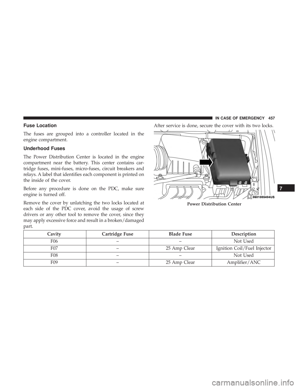
The Power Distribution Center is located in the engine
compartment near the battery. This center contains car-
tridge fuses, mini-fuses, micro-fuses, circuit breakers and
relays. A label that identifies each component is printed on
the inside of the cover.
Before any procedure is done on the PDC, make sure
engine is turned off.
Remove the cover by unlatching the two locks located at
each side of the PDC cover, avoid the usage of screw
drivers or any other tool to remove the cover, since they
may apply excessive force and result in a broken/damaged
part.After service is done, secure the cover with its two locks.
Cavity
Cartridge Fuse Blade FuseDescription
F06 ––Not Used
F07 –25 Amp Clear Ignition Coil/Fuel Injector
F08 ––Not Used
F09 –25 Amp Clear Amplifier/ANC
Power Distribution Center
7
IN CASE OF EMERGENCY 457